
Related Manuals for Tenma 72-7615


Summary of Contents for Tenma 72-7615
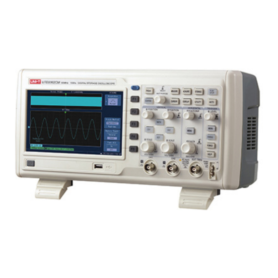
- Page 1 Digital Storage Oscilloscope Model No. 72-7615, 72-7620, 72-7625 72-7635 and 72-7640...
-
Page 2: Product Overview
When using electrical appliances, basic safety precautions should always be followed to reduce the risk of fire, electric shock and injury to persons or property. Read all instructions before using the appliance and retain for future reference. • This meter is designed to meet IEC61010-1, 61010-2-032, and 61010-2-033 in Pollution Degree 2, Measurement Category (CAT II 150V when switched to 1X and 300V CAT II when switched to 10X) and double Insulation. -
Page 3: Operating Parameters
OPERATING PARAMETERS • The oscilloscope also has high performance index and powerful functions required for faster measurements. Faster signals can be observed with the oscilloscope via 500MS/s (or 1GS/s) real‐time sampling and 25GS/s (or 50GS/s) equivalent sampling. • Powerful trigger and analysis ability make it easier to capture and analyse waveforms. -
Page 4: Operation
OPERATION • Boot check • Power on the unit at the rear followed by the soft power button on the front panel. • The oscilloscope then run through a set on self test functions followed by the display screen showing. •... - Page 5 Using the AUTOSET function • Connect the signal to be measured to the signal input channel. • Press AUTO and the oscilloscope will scan the time base and trigger mode and set the vertical deflection factor. You can manually adjust further after this process to get the optimum display.
-
Page 6: Instrument Setup
INSTRUMENT SETUP Vertical system setup • Each channel CH1 or CH2 has it’s own vertical menu. Each channel should be set up individually. • Press CH1 or CH2 and the system will display the operation menu for that channel. Functions Menu Setup Notes Intercepts the DC quantities of the input signal. - Page 7 Channel bandwidth setup • If for example a signal is applied to CH1 which is a pulse signal that contains high frequency oscillation. • Press CH1 to select Channel1. • Press F2 to set the BANDWIDTH LIMIT OFF so it is set up as full bandwidth. •...
- Page 8 Operating Math functions • Math functions are displays of +, -, ÷ FFT mathematical results of CH1 and CH2. The menu options are:- Functions Menu Setup Notes Type Math To carry out +, -, x, ÷ functions Signal source 1 Set signal source 1 as CH1 waveform Set signal source 1 as CH2 waveform Operator...
-
Page 9: Reference Waveform
Select the FFT window • Assuming the YT waveform is constantly repeating itself, the oscilloscope will carry out FFT conversion of time record of a limited length. When this cycle is a whole number, the YT waveform will have the same amplitude at the start and finish. There is no waveform interruption. - Page 10 Note: If the stored waveform is on external disk press F5 to select between DSO and USB and select USB having inserted the drive into the USB port. The recalled waveform will be displayed on the screen. Press CANCEL to go back to the previous menu. Press REF B and select the second signal source for the math function repeating step 3 Note: To measure and observe such waveforms you can compare the current waveform...
-
Page 11: Icon Definitions
Icon definitions Represents the memory position of the current waveform. Represents the memory position of the triggering point. Represents the position of the triggering point in the current waveform window. Horizontal time base (main time base) ie: sec/div. Horizontal distance between the triggering position and the window centre point. Definitions •... -
Page 12: Edge Trigger
• Generally adjusting the time base lower will result in appropriately Lissajous figures of better display quality. Auto measurement mode Cursor measurement mode Reference or math waveform Setting up the Trigger system • Triggering decides when the oscilloscope collects data and displays waveforms. Once the trigger is correctly set up, it can convert unstable display into significant waveforms. - Page 13 Pulse Trigger • Pulse trigger means determining the triggering time based on the pulse width. You can acquire abnormal pulse by setting the pulse width condition. • Adjust the pulse width from 2ns~10s by turning the control on the upper front panel. Functions Menu Setup Notes...
-
Page 14: Video Trigger
Video Trigger • By selecting video trigger you can carry out field or line trigger with NTSC or PAL standard video signals. Default trigger coupling is DC. Functions Menu Setup Notes Type Video Set Ch1 as the trigger signal Set CH2 as the trigger signal Trigger source Set the external trigger input channel as the trigger signal EXT/5... - Page 15 Adjusting the Holdoff time • You can adjust the Holdoff time to observe complicated waveforms. Holdoff time means the waiting time for the trigger to be ready for use again. During this time the oscilloscope will not trigger until the Holdoff is complete. •...
- Page 16 OPERATION Run/Stop • When the RUN/STOP key is pressed, a green light will be on, indicating the RUN status. • When the key is pressed again and a red light appears, it indicates the STOP status. • The RUN state enables the oscilloscope to be in continuous acquisition. •...
- Page 17 Setting up the Sampling System • The ACQUIRE button on the control panel is the function key for the sampling system. Functions Menu Setup Notes Sample Turn on the ordinary sampling mode Peak detect Turn on the peak detect mode Acquisition Mode Average Set the average sampling and display the average number...
-
Page 18: Memory Depth
Sampling Mode is when the oscilloscope reconstructs the waveform by sampling signals at regular intervals. To avoid mixed envelope, select Peak Detect. In this mode the oscilloscope identifies the maximum and minimum values of the input signals at each sampling interval and use these values to display the waveform. - Page 19 Note: Please use deep memory if you want to view more waveform details. Fast Acquisition is recommended in order to capture certain abnormal signal. Fast Acquisition is valid only within 1 ms/div~1 O0ns/div for single channel and 1 ms/div~200ns/div for dual channels. Setting up the Display System •...
- Page 20 Storage Menu Setup Notes Types Waveform Select the waveform save and recall menu Select the waveform from CH1 Information source Select the waveform from CH2 Set and select the position in which the waveform is saved in Store 1~10 the internal memory. Adjust using the multi-function control Output ---- Enter into USB menu...
- Page 21 Setting up Auto Measurement • The AUTO button on the control panel is the function key for auto measurement. The oscilloscope is capable of measuring 20 waveform parameters. • Press MEASURE to enter the parameter measurement display menu which has five zones for simultaneous display of measurement values assigned to function keys F1 to F5 respectively.
- Page 22 Functions Menu Setup Notes All parameters ----- Display/close all parameters - F5 closes Press F2 and select parameters required using multi- Parameter Setting ----- function control, press to confirm (4 parameters max) Indicator ----- Select the Indicator for parameter measurement Delete Deletes all parameter settings Next...
-
Page 23: Timing Parameters
Voltage Parameters • The following parameters can be measured automatically: Vmax: Voltage at the highest point with respect to GND Vmin: Voltage at the lowest point with respect to GND Vtop: Highest stable voltage Vbase: Lowest stable voltage Middle: Midpoint between highest and lowest stable voltage Vpp: Vmax –... - Page 24 Cursor Measurement • The CURSOR button on the control panel is the function key for cursor measurement. • Adjust the cursor position by turning the multi-function control. Functions Menu Setup Notes Types Time Select the time measurement cursor Independently shift any one of the two cursors. Simultaneously shift the two cursors while maintaining the Modes Modes...
- Page 25 Recording Setup Notes Menu Select CH1 as the recording signal source Record Select CH2 as the recording signal source Cancel Quit the current record menu and return to previous menu Stop recording (F3) Playback button - the system plays back and displays the position reference in the lower RH corner.
-
Page 26: Auto Setting
• Stop settings menu. Functions Options Description The test function stops after it reaches a specified pass Pass count count number Stop type The test function stops after it reaches a specified fail count Fail count number >=,<= Stop condition setting Condition Use the multi-purpose control to select the stop condition Threshold... -
Page 27: Functions Menu
Functions Menu Setup Bandwidth restriction Full bandwidth or 20MHz to keep the present setting. Vertical scale coefficency Based on signal amplitude VOLTS/DIV Coarse tuning Opposite phase Open or close to keep present setting. Horizontal position Automatic tuning SEC/DIV To regulate based on signal frequency Acquisition mode Setting: normal sampling, peak value, average Sampling mode... -
Page 28: Specification
SPECIFICATION Sampling Sampling modes Real time Equivalence 72-7615 72-7620 1GS/s 50GS/s Sampling rates 72-7625 72-7635 2GS/s 25GS/s 72-7640 All channels reach N times of sampling Average value Average value and N should be chosen among 2, 4, 8,16, 32, 64, 128, 256 and 512... - Page 29 Vertical A/D converter 8-bit resolution 72-7640 72-7635 2mV/div~5V/div Deflection factor VOLTS/DIV 72-7625 Range at input BNC 72-7620 2mV/div~10V/div 72-7615 (at the input BNC port) Shift Scope ±8div 72-7640 200MHZ 72-7635 300MHZ Analogue bandwidth 72-7625 200Mhz 72-7620 100MHz 72-7615 60MHz 72-7640...
-
Page 30: Pulse Trigger
Trigger Internal ≤1 div Trigger sensitivity ≥60mV EXT/5 ≤300mV Internal ±8 div from the centre of the screen Trigger level scope ±800mV EXT/5 ±4.0V ± (0.3 div x V/div) within ± 4 div from the Internal Trigger level accuracy centre of the screen) (Typical) applied on signals ±... -
Page 31: Interface Function
Measurement Voltage difference (rV) between cursors, Manual Mode time difference (rT) between cursors, rT countdown (Hz)(1/rT) Cursor Tracking mode Voltage or time value of waveform points Auto measurement Allows cursor or display during auto mode measurement Maximum value,minimum value,top value,bottom value,medium value, peak peak value, amplitude value,average value,mean square root value, period average value, period mean square Auto measurement... -
Page 32: Maintenance
Dimensions WIDTH 330mm Size HEIGHT 155mm DEPTH 130mm Weight Exc Packaging 2.9kg Inc Packaging 5.0kg IP rating IP20 Adjustment interval Recommended calibration interval is one year MAINTENANCE Cleaning • Periodically wipe the case with damp cloth and mild detergent. Do not use abrasives or solvents for cleaning.
Need help?
Do you have a question about the 72-7615 and is the answer not in the manual?
Questions and answers