Table of Contents
Advertisement
Quick Links
Advertisement
Table of Contents

Related Manuals for FLIR CM94


Summary of Contents for FLIR CM94
- Page 1 USER MANUAL True RMS AC/DC 2000A Utility Clamp Meter Model CM94...
- Page 3 USER MANUAL True RMS AC/DC 2000A Utility Clamp Meter #NAS100019; r. AC/59959/59961; en-US...
-
Page 5: Table Of Contents
Table of contents Advisories ................1 Copyright ..............1 Quality Assurance ............1 Documentation ............1 Disposal of Electronic Waste ......... 1 Introduction................2 Safety ................3 General Safety Information ........... 3 Safety Terms Used In This Manual ......... 3 Warning and Caution Statements ........3 International Electrical Symbols ........ - Page 6 Table of contents Battery Replacement..........22 Meter Storage............22 Specifications..............23 General Specifications..........23 DC Voltage Specifications .......... 24 LoZ (DC Voltage) Specifications........24 AC Voltage Specifications........... 24 LoZ (AC Voltage) Specifications........25 VFD (low pass filter) AC Voltage Specifications ....25 PEAK HOLD Capture Mode Specifications.....
-
Page 7: Advisories
Advisories 1.1 Copyright ©2019, FLIR Systems, Inc. All rights reserved worldwide. No parts of the software including source code may be reproduced, transmitted, transcribed or translated into any language or computer language in any form or by any means, electronic, magnetic, optical, manual or otherwise, without the prior written permission of FLIR Systems. -
Page 8: Introduction
Introduction The CM94 is a high accuracy, rugged measurement instrument intended for the electrical utility and industrial maintenance professional for inspecting and troubleshooting high voltage/current electrical infrastructure systems and equipment. The low input impedance mode (LoZ) helps determine whether a measured voltage is ‘real’... -
Page 9: Safety
Safety 3.1 General Safety Information This user manual contains information and warnings that must be followed for operating the instrument safely and maintaining the instrument in a safe oper- ating condition. If the instrument is used in a manner not specified by the man- ufacturer, the protection provided by the instrument may be impaired. - Page 10 Safety WARNING To avoid electrical shock hazard, observe the proper safety precautions when working with voltages above 60 VDC or 30 VAC rms. These voltage levels pose a potential shock haz- ard to the user. Before and after hazardous voltage measurements, test the voltage func- tion on a known source such as line voltage to determine proper meter functioning.
-
Page 11: International Electrical Symbols
Safety 3.4 International Electrical Symbols Caution! Refer to the explanation in the user manual. Caution! Risk of electrical shock. Earth ground. Double/reinforced insulation. Fuse. AC (alternating current). DC (direct current). Application around, and removal from, hazardous live conductors is permitted. 3.5 CENELEC Directives This instrument conforms to CENELEC Low-voltage directive 2014/35/EC, Electromagnetic compatibility directive 2014/30/EU and RoHS directive 2011/... -
Page 12: Descriptions
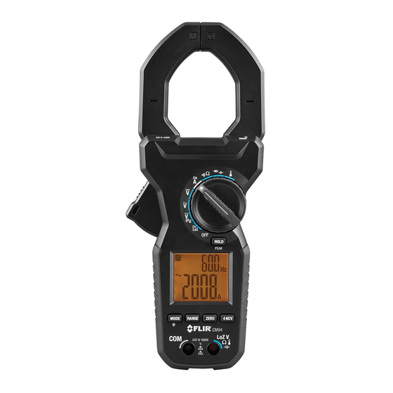
Descriptions 4.1 Product Description Figure 4.1 Product Description 1. Non-Contact Voltage Detector (NCV) antenna 2. Clamp jaws 3. Conductor alignment icon 4. Hand/finger barrier 5. Jaw opening trigger 6. Display 7. RANGE button 8. MODE /Display backlight button 9. Negative (COM) input terminal 10. -
Page 13: Control Button Descriptions
Descriptions 4.2 Control Button Descriptions Short press to toggle AC/DC where necessary, to select an option at a mul- ti-option rotary switch position, and to toggle ℃ and ℉ units in temperature measurement mode. Long press to toggle the display backlight ON/OFF. Short press to change to Manual range mode, subsequent presses will step through available ranges. -
Page 14: Display Description
Descriptions 4.4 Display Description Figure 4.2 Display Description 1. Auto Range 2. Data hold 3. Diode mode 4. 1999 count secondary display 5. Battery status 6. Units of measure 7. 6000 count primary display 8. Relative mode 9. Low impedance mode 10. -
Page 15: Meter Operation
Meter Operation NOTE Before operating the device, you must read, understand, and follow all instructions, dangers, warnings, cautions, and notes. NOTE When the meter is not in use, the function switch should be set to the OFF position. NOTE When connecting the probe leads to the device under test, connect the negative lead before connecting the positive lead. -
Page 16: Out-Of-Range Alert
Meter Operation 5.4 Out-of-Range Alert If the input is out-of-range, OL is displayed. Please do not attempt to make measurements beyond the specified ranges of the meter. 5.5 Display Hold Function After taking a measurement, short press the HOLD button to freeze a reading. Press the HOLD button again to return to normal operation. - Page 17 Meter Operation Figure 5.2 AC Voltage (left) and DC Voltage (right) Measurement Setups 1. Set the function switch to the AC Voltage or DC Voltage position. 2. Insert the black test lead into the negative (COM) terminal and the red test lead into the positive terminal.
-
Page 18: Loz Voltage Measurements
Voltage measurement details. When you turn the rotary dial to the LoZ position, the display will show ‘auto’ indicating that the CM94 will automatically detect the measured signal as AC or DC. 5.9 Low Pass Filter (VFD) AC Voltage Measurements CAUTION Use caution when the measured voltage is greater than 30V DC or AC rms. -
Page 19: Current Clamp Measurements
Meter Operation 5.10 Current Clamp Measurements WARNING Do not measure current on a circuit if the voltage increases to more than 1000 V. This can cause damage to the instrument and can cause injury to persons. WARNING Do not use the meter to measure current above the rated frequency. This may cause the magnetic circuits in the jaws to reach hazardous temperatures. -
Page 20: Resistance Measurements
Meter Operation Figure 5.3 AC Current (left) and DC Current (right) Measurement Setups Taking AC or DC Current Clamp Measurements 1. Set the function switch to the Ampere position . 2. Short press the MODE button to select AC or DC current mode. 3. -
Page 21: Continuity Measurements
Meter Operation Figure 5.4 Resistance Measurement Setup. 1. Set the function switch to the Resistance position. 2. If necessary, short press the MODE button to select the Resistance function. 3. Insert the black test lead into the negative (COM) terminal and the red test lead into the positive terminal. -
Page 22: Diode Measurements
Meter Operation Figure 5.5 Continuity Measurements. Note the CLOSED (0.00) and OPEN (OL) circuit examples. 1. Set the function switch to the Continuity position. 2. If necessary, short press the MODE button to select the Continuity function. 3. Insert the black test lead into the negative (COM) terminal and the red test lead into the positive terminal. - Page 23 Meter Operation Figure 5.6 Diode Testing. Note the two test positions, forward and reverse bias. 1. Set the function switch to the Diode position. 2. If necessary, short press the MODE button to select the Diode function. 3. Insert the black test lead into the negative (COM) terminal and the red test lead into the positive terminal.
-
Page 24: Capacitance Measurements
Meter Operation 5.14 Capacitance Measurements WARNING Do not perform capacitance tests before removing power to the capacitor under test and discharging it through an appropriate resistance load. Injury to persons can occur. Figure 5.7 Capacitance Measurement Setup. 1. Set the function switch to the Capacitance position. -
Page 25: Type-K Thermocouple Measurements
Meter Operation 5.15 Type-K Thermocouple Measurements CAUTION The supplied thermocouple is rated for -4 ~ 482℉ (-20 ~ 250℃) only, it is not rated for the entire specified temperature range of the meter. Figure 5.8 Thermocouple Temperature Measurements. 1. Set the function switch to the Temperature position. #NAS100019;... -
Page 26: Non-Contact Ac Voltage Detector
Figure 5.9 Non-Contact AC Voltage Detection (NCV). 1. Set the function switch to the AC Voltage position and remove the test leads from the CM94. 2. Short press the NCV button. The display will show the EF symbol (electro- motive force). - Page 27 3. The voltage detection antenna is located at the tip of the clamp jaws, just to the right of the jaw opening seam (with the meter facing you). 4. Hold the CM94 with hand/fingers behind the safety barrier and place the antenna near the source of potential voltage. Leave the jaws closed while using the voltage detector.
-
Page 28: Maintenance
Maintenance 6.1 Cleaning With the CM94 OFF, wipe the meter housing with a damp cloth as needed. Do not use abrasives or solvents. Dry completely before use. 6.2 Battery Replacement The battery compartment is located on the back of the CM94 secured by two screws. -
Page 29: Specifications
Specifications 7.1 General Specifications Display Primary: 6000 count backlit LCD Secondary: 1999 count backlit LCD Polarity Automatic Update rate 5 readings per second, nominal Operating temperature 14 ~ 122℉ (–10 ~ 50℃) Relative humidity Maximum relative humidity 80% for temper- ature up to 88℉... -
Page 30: Dc Voltage Specifications
Specifications Weight 700 g (24.7 oz.) Jaw opening/Conductor diameter 55 mm (2.2 in.) maximum Electrical specification accuracy ± (% reading + number of digits) or as oth- erwise specified, at 73.4℉ (23℃) ± 9℉ (5℃). Accessories Supplied: Test lead pair, Type-K thermo- couple with banana-type connectors, printed Quick Start, and soft carrying pouch. -
Page 31: Loz (Ac Voltage) Specifications
Specifications 7.5 LoZ (AC Voltage) Specifications Range and Resolution Frequency Accuracy 6.000 V, 60.00 V, 600.0 V, & 50 Hz ~ 60 Hz ± (1.5% + 5 digits) 1000 V LoZ ACV threshold: > 1.5V AC, and < –1.5V AC Input impedance: Initially approx. -
Page 32: Capacitance Specifications
Specifications 7.10 Capacitance Specifications Range and Resolution Accuracy 60.00 nF, 600.0 nF, 6.000 μF ± (2.0% + 5 digits) 60.00 μF, 600.0 μF ± (3.5% + 5 digits) 2000 μF ± (4.0% + 5 digits) 1. Accuracy specified with film capacitor or better 2. -
Page 33: Hz Line Level Frequency Specifications
Specifications 200.0 A ± (2.5% + 5 digits) 0 ~ 500 A ± (3.0% + 5 digits) 40 Hz ~ 50 Hz and 60 Hz~ 400 Hz 500 ~ 1000 A ± (3.5% + 5 digits) 1000 ~ 2000 A Unspecified 1. -
Page 34: Non-Contact Ac Voltage Detector (Ncv)
Specifications 7.16 Non-Contact AC Voltage Detector (NCV) Typical Voltage Tolerance Bar Graph Indication 40 V 10 V ~ 90 V 1 dash ( — ) 100 V 64 V ~ 162 V 3 dashes ( — — —) 165 V 125 V ~ 1000 V 5 dashes ( —... -
Page 35: Three-Year Warranty
Three-Year Warranty Please register your product within 60 days of purchase. Register your prod- uct at https://support.flir.com/prodreg or use the QR Code. Read the warranty text at the links provided. Figure 8.1 Product Registration QR Code #NAS100019; r. AC/59959/59961; en-US... -
Page 36: Customer Support
Customer Support Repair, Calibration, and Technical Support: https://support.flir.com. 9.1 Corporate Headquarters FLIR Systems, Inc. 27700 SW Parkway Avenue Wilsonville, OR 97070 USA #NAS100019; r. AC/59959/59961; en-US... - Page 38 Customer support http://support.flir.com Copyright © 2019, FLIR Systems, Inc. All rights reserved worldwide. Disclaimer Specifications subject to change without further notice. Models and accessories subject to regional market considerations. License procedures may apply. Products described herein may be subject to US Export Regulations.
Need help?
Do you have a question about the CM94 and is the answer not in the manual?
Questions and answers