Table of Contents
Advertisement
Advertisement
Table of Contents

Related Manuals for FLIR CM42


Summary of Contents for FLIR CM42
- Page 1 USER MANUAL FLIR True RMS 400A Clamp Meter Series Models CM42, CM44, and CM46...
-
Page 2: Table Of Contents
5.10 Resistance Measurements 5.11 Continuity Tests 5.12 Capacitance Measurements (CM44 and CM46) 5.13 Temperature Measurements (CM44 and CM46) 5.14 Diode Tests 5.15 Relative / DC Zero Modes (CM44 and CM46) 5.16 MIN/MAX/AVG Recording FLIR CM4x USER MANUAL Document ID: CM4x-en-US_AA... - Page 3 5.20 PEAK Mode (CM44 and CM46) 6. MAINTENANCE 6.1 Troubleshooting Tips 6.2 Accuracy and Calibration 6.3 Cleaning and Storage 6.4 Battery Replacement 7. SPECIFICATIONS 7.1 General specifications 7.2 Electrical specifications 8. TECHNICAL SUPPORT 9. WARRANTY FLIR CM4x USER MANUAL Document ID: CM4x-en-US_AA...
-
Page 4: Disclaimers
1. Disclaimers 1.1 Copyright © 2016, FLIR Systems, Inc., All rights reserved worldwide. No parts of the software including source code may be reproduced, transmitted, transcribed or translated into any language or computer language in any form or by any means, electronic, magnetic, optical, manual or otherwise, without the prior written permission of FLIR Systems. -
Page 5: Safety
Keep hands/fingers behind the hand/finger barriers (of the meter and the test leads) during measurement. Inspect test leads, connectors, and probes for damaged insulation or exposed metal FLIR CM4x USER MANUAL Document ID: CM4x-en-US_AA... -
Page 6: International Electrical Symbols
AC (Alternating Current) DC (Direct Current) Application around, and removal from, hazardous live conductors is permitted CENELEC DIRECTIVES The instruments conform to CENELEC Low-voltage directive 2014/35/EC, Electromagnetic compatibility directive 2014/30/EU and RoHS directive 2011/65/EU. FLIR CM4x USER MANUAL Document ID: CM4x-en-US_AA... -
Page 7: Introduction
3. Introduction Thank you for selecting the FLIR Auto Range, True RMS 400A Clamp Meter with Low Pass Filter and Accu-Tip low current measurement technology. All meters in this series measure 400A AC, 600V AC/DC, Resistance, Continuity, Frequency, and Diode. Features include Non-Contact Voltage Detector, Data Hold, MIN/MAX/AVG, and display backlighting. -
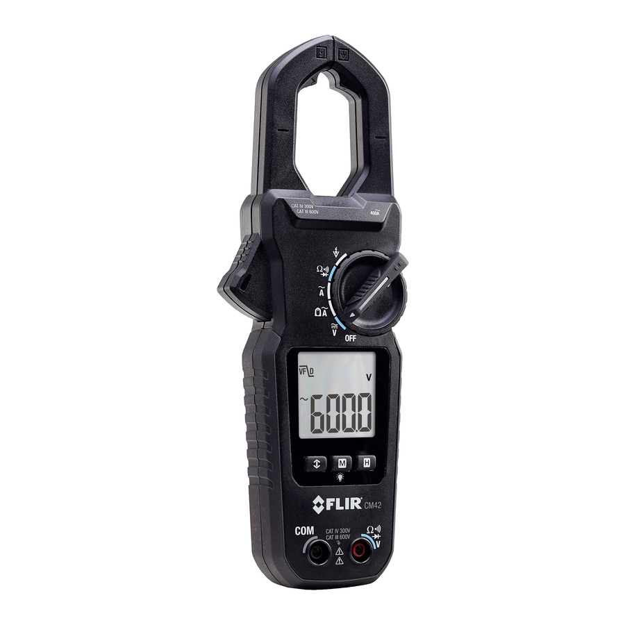
Page 8: Description
6. COM (negative -) Probe Input jack 7. Clamp jaw trigger 8. Clamp jaws 9. Low current Accu-Tip clamp area Figure 4-1 Meter Description Note: Battery compartment and Warning text label on back of meter. FLIR CM4x USER MANUAL Document ID: CM4x-en-US_AA... -
Page 9: Function Switch Positions
Measure electric field (EF) using the non-contact voltage detector Measure AC or DC current through the clamp jaws (CM46) Measure AC current in the large clamp jaw area (CM42 and CM44) Measure low AC current through the small clamp jaw area (Accu- ). -
Page 10: Function Buttons
Refer to Fig. 4-2 above for the display icon descriptions below: Meter is displaying maximum (up arrow), minimum (down arrow) or average reading (up and down arrows) 80ms PEAK current/voltage rms mode Low current Accu-Tip mode Auto range mode Display Hold mode FLIR CM4x USER MANUAL Document ID: CM4x-en-US_AA... - Page 11 Volt. Unit of measure for Voltage Farad. Unit of measure for Capacitance Hertz. Unit of measure for Frequency (kilo) (milli) (micro) VFD mode (low pass filter) icon Relative Zero CM44 Relative & DC Zero CM46 FLIR CM4x USER MANUAL Document ID: CM4x-en-US_AA...
-
Page 12: Operation
The meter automatically selects the most appropriate measurement scale. The indicator is displayed to inform the user that Auto Range is functioning. 5.4 Out-of-range Warning If the input is out-of-range, OL is displayed. FLIR CM4x USER MANUAL Document ID: CM4x-en-US_AA... -
Page 13: Voltage Measurements
3. Connect the probe leads in parallel to the part under test. 4. Use the M (mode) button to step through the available sub-functions: ACV, DCV, ACV+DCV (CM46 only), Line Frequency (Hz), Electric Field (EF) detection (*CM42 has a dedicated switch position for EF); see Section 5.6 Electric Field (EF) -
Page 14: Electric Field (Ef) Detection
1. Set the function switch to the position (for CM44 and CM46) or the dedicated EF position (CM42). 2. If necessary, use the M (mode) button to step to the EF function 3. For non-contact EF detection ensure that the test leads are disconnected from the meter. -
Page 15: Standard Current Clamp Measurements
Align the conductor(s) to the Jaws center indicators as close as possible. Adjacent current-carrying devices such as transformers, motors and conductor wires may affect measurement accuracy. Figure 5-3 Correct and incorrect clamping FLIR CM4x USER MANUAL Document ID: CM4x-en-US_AA... - Page 16 5. Press the trigger to open the clamp jaws and fully enclose one pole of a circuit— refer to Fig. 5-3. For optimum results, center the conductor in the jaws. 6. Read the current value on the display. FLIR CM4x USER MANUAL Document ID: CM4x-en-US_AA...
-
Page 17: Low Current Accu-Tip Tm Clamp Measurements
3. Press the trigger to open the clamp jaws. Fully enclose the conductor(s) of a single pole—refer to Figure 5.4 4. Read the current value on the display. Figure 5-4 Low Current Clamp Measurements FLIR CM4x USER MANUAL Document ID: CM4x-en-US_AA... -
Page 18: Dc A Current Test Lead Measurements (Cm44 And Cm46)
Flame lifting off burner head (ground), or not continuously in contact with the flame rod Temperature > 600 F (316 C) at the flame electrode insulator causing short to ground. Figure 5-5 ADC Measurements FLIR CM4x USER MANUAL Document ID: CM4x-en-US_AA... -
Page 19: Resistance Measurements
5. If the resistance measurement <10 Ω, the meter will beep. If the resistance measurement is > 250 Ω, the meter will not beep. Between 10 Ω and 250 Ω, the meter will stop beeping at an unspecified point. FLIR CM4x USER MANUAL Document ID: CM4x-en-US_AA... -
Page 20: Capacitance Measurements (Cm44 And Cm46)
5. Read the capacitance value on the display. Note: For very large capacitance values, several seconds may be required for the measurement to settle and for the final reading to stabilize. Figure 5-7 Capacitance Measurements FLIR CM4x USER MANUAL Document ID: CM4x-en-US_AA... -
Page 21: Temperature Measurements (Cm44 And Cm46)
4. Touch the tip of the temperature probe to the surface under test or simply hold the temperature probe in air to measure the air temperature (see Fig. 5-8). 5. Read the temperature value on the display. Figure 5-8 Temperature Measurements FLIR CM4x USER MANUAL Document ID: CM4x-en-US_AA... -
Page 22: Diode Tests
5. If the reading is between 0.40 and 0.90V in one direction and OL (overload) in the opposite direction, the component is good. If the measurement is 0V in both directions (shorted) or OL in both directions (open), the component is bad. Figure 5-9 Diode Tests FLIR CM4x USER MANUAL Document ID: CM4x-en-US_AA... -
Page 23: Relative / Dc Zero Modes (Cm44 And Cm46)
The VFD feature eliminates high frequency noise in voltage measurements by means of a low-pass filter. The VFD mode is designed for variable frequency drive (VFD) measurements. This mode is always active for ACV and Hz measurements and the VFD display icon is displayed FLIR CM4x USER MANUAL Document ID: CM4x-en-US_AA... -
Page 24: Display Hold Function
Peak mode is active. Measurements made with Peak mode activated capture inrush current or voltage RMS values. The Peak measurement window is 80ms in duration. Auto-Power-Off is disabled automatically in this mode. A long press of the button switches this feature off. FLIR CM4x USER MANUAL Document ID: CM4x-en-US_AA... -
Page 25: Maintenance
The rear battery compartment locking screw has a LOCK and UNLOCK position. Replace the two (2) standard 1.5V AAA batteries, observing correct polarity. Secure the battery compartment cover before use. Figure 6-1 Battery installation FLIR CM4x USER MANUAL Document ID: CM4x-en-US_AA... -
Page 26: Specifications
APO Consumption: 5A typical Dimensions (LxWxH): 8.8 x 3.0 x 1.5 in. (223 x 76 x 37mm) for CM46; 8.5 x 3.0 x 1.5 in. (217 x 76 x 37mm) for CM42 and CM44 FLIR CM4x USER MANUAL Document ID: CM4x-en-US_AA... - Page 27 Weight: 8.3 oz. (234g) for Model CM46; 6.6 oz. (186g) for Models CM42 and CM44 Jaw opening & Conductor diameter: 1.2 in. (30mm) maximum Accessories: Test lead set, Quick Start Guide, soft carrying pouch, banana plug K-type thermocouple (Models CM44 and CM46)
-
Page 28: Electrical Specifications
Capacitance (Models CM44 and CM46) RANGE Accuracy 200.0F, 2500F 2.0% + 4d Accuracy specified for film capacitors or better Diode Test RANGE Accuracy 2.000V 1.5% + 5d Test Current: 0.3mA typical; Open Circuit Voltage: < 3.5VDC typical FLIR CM4x USER MANUAL Document ID: CM4x-en-US_AA... - Page 29 RANGE Accuracy 50Hz ~ 60Hz 60.00A 1.5% + 5d (CM46); 2.0% + 5d (CM42 and CM44) Induced error from adjacent current-carrying conductor: <0.01A/A for Model CM46 <0.06A/A for Models CM42 and CM44 Specified with Relative/DC Zero mode applied to offset non-zero residual readings Add 10d to the specified accuracy @ <...
- Page 30 <0.01A/A for Models CM46 <0.06A/A for Models CM44 & CM42 For CM44 & CM42, specified accuracy is for measurements made at the jaw center. When the conductor is not positioned at the jaw center, add 2% to specified accuracy for position errors For CM44 &...
-
Page 31: Technical Support
Detector: Located Inside the top of the stationary jaw 8. Technical Support Main Website http://www.flir.com/test Technical Support Website http://support.flir.com Technical support Email TMSupport@flir.com Service/Repair Support Email Repair@flir.com Support Telephone number +1 855-499-3662 option 3 (toll-free) FLIR CM4x USER MANUAL Document ID: CM4x-en-US_AA... -
Page 32: Warranty
Purchaser, and for the cost of repackaging and returning the Product to Purchaser. Any non-warranty repair of a Product is warranted for one hundred eighty days (180) days from the date of return shipment by FLIR to be free from defects in materials and workmanship only, subject to all of the limitations, exclusions and disclaimers in this document. - Page 33 Corporate Headquarters FLIR Systems, Inc. 2770 SW Parkway Avenue Wilsonville, OR 97070 USA Telephone: +1 503-498-3547 Customer Support Technical Support Website http://support.flir.com Technical Support Email TMSupport@flir.com Service and Repair Email Repair@flir.com Customer Support Telephone +1 855-499-3662 option 3 (toll free) Publication Identification No.:...
Need help?
Do you have a question about the CM42 and is the answer not in the manual?
Questions and answers