Table of Contents
Advertisement
Quick Links
Advertisement
Table of Contents

Related Manuals for FLIR CM57-2


Summary of Contents for FLIR CM57-2
- Page 1 USER MANUAL Flex Clamp Meter with Bluetooth ® MODEL CM57–2...
- Page 3 USER MANUAL Flex Clamp Meter with Bluetooth #NAS100152; r. AB/91610/91610; en-US...
-
Page 5: Table Of Contents
Table of contents Advisories ................1 Copyright ..............1 Quality Assurance ............1 Documentation ............1 Disposal of Electronic Waste ......... 1 Safety ................2 Safety Notes.............. 2 Safety Warnings ............2 Safety Cautions............3 FCC Compliance ............3 Industry Canada Compliance ........4 Introduction................5 Key Features ............. - Page 6 Table of contents Specifications..............15 General Specifications..........15 AC Current Electrical Specifications......16 CUSTOMER SUPPORT ............18 Warranty ................19 #NAS100152; r. AB/91610/91610; en-US...
-
Page 7: Advisories
The documentation must not, in whole or part, be copied, photocopied, repro- duced, translated or transmitted to any electronic medium or machine-read- able form without prior consent, in writing, from FLIR Systems, Inc. Names and marks appearing on the products herein are either registered trademarks or trademarks of FLIR Systems, Inc. -
Page 8: Safety
• Before operating the device, you must read, understand, and follow all in- structions, dangers, warnings, cautions, and notes. • FLIR Systems reserves the right to discontinue models, parts or accesso- ries, and other items, or to change specifications at any time without prior notice. -
Page 9: Safety Cautions
Safety 2.3 Safety Cautions CAUTION Do not use the device for a procedure that it is not made for. This can cause damage to the protection. This symbol, adjacent to another symbol, indicates the user must refer to the manual for further information Do not apply or remove clamp from HAZARDOUS LIVE conductors Equipment protected by double or reinforced insulation Battery symbol... -
Page 10: Industry Canada Compliance
Safety 1. Reorient or relocate the receiving antenna. 2. Increase the separation between the equipment and receiver. 3. Connect the equipment into an outlet on a circuit different from that to which the receiver is connected. 4. Consult the dealer or an experienced radio/TV technician for help. CAUTION Exposure to Radio Frequency Radiation. -
Page 11: Introduction
Introduction Thank you for choosing the FLIR Flex Clamp with Bluetooth that can measure up to 3000 A AC RMS. This device is a professional CAT IV 600 V CAT III 1000 V instrument that offers data recording, Bluetooth, auto power off (APO), data hold, display backlight, and worklights. -
Page 12: Product Description
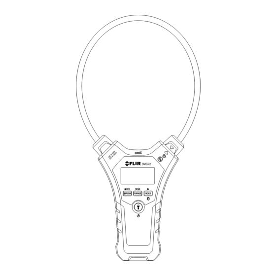
Product Description 4.1 Meter Description Figure 4.1 Meter Description (see numbered list below). 1. Worklights 2. Flexible current clamp coil 3. Display 4. INRUSH / REC (Record) button 5. Power / Worklight button 6. RANGE / SEND button 7. HOLD / Start-Stop Record / Bluetooth button 8. -
Page 13: Display Icons Description
Product Description 4.2 Display Icons Description Display hold Amperes Bluetooth Battery status Auto power off Inrush current Bulk data Memory mode Auto range transmission 4.3 Control Buttons Description • Short press to access INRUSH mode • Long press to access Record Memory mode •... -
Page 14: Operation
Operation CAUTION Before operating the device, please read and understand all Warning and Caution state- ments and follow all instructions and notes. 5.1 Powering the Meter The meter is powered by two (2) AAA 1.5 V batteries (located in the rear com- partment). -
Page 15: Ac Current Measurements
Operation 5.4 AC Current Measurements WARNING Ensure that power to the device under test is OFF before starting this procedure. Switch power to the device under test on only after the clamp has been safely attached to the de- vice under test. CAUTION Do not move fingers above the LCD at any time during a test. - Page 16 Operation 3. Fully enclose (and centre) only one conductor of the device under test with the flexible clamp probe (Fig. 5.2). Figure 5.2 Correct (left) and incorrect (right) clamping. Figure 5.3 Centring the conductor in the clamp. 4. Re-secure the clamp lock (1) after clamping around a single conductor. #NAS100152;...
-
Page 17: Inrush Current
Operation 5. Do not attempt to measure current higher than the specified current limit. 6. Switch the meter ON and then switch power to the device under test ON. Never move fingers above the display area when running a test. 7. -
Page 18: Data Recording And Data Transfer
Operation 2. The display will show the Inrush icon and the display digits will switch to dashes. 3. The meter then waits for a current signal that exceeds the threshold. 4. When ready, turn on power to the device under test. The meter will capture the highest reading detected during a 100 ms window. -
Page 19: Transferring Recorded Readings With Bluetooth
Operation 1. With the meter OFF, press both the POWER and RANGE buttons simulta- neously to access the ID number. The display will show ‘Idxx’. 2. Use the RANGE button to increment the ID number. 3. When the desired number is shown, short press the button to save the 4. -
Page 20: Maintenance
6.3 Disposal of Electronic Waste As with most electronic products, this equipment must be disposed of in an environmentally friendly way, and in accordance with existing regulations for electronic waste. Please contact your FLIR Systems representative for more details. #NAS100152; r. AB/91610/91610; en-US... -
Page 21: Specifications
Specifications 7.1 General Specifications Clamp Jaw Flexible type with locking mechanism Coil diameter 7.5 mm (0.3 in.) Coil tip: 13 mm (0.5 in.) Coil bend radius 80 mm (3.1 in.) Display 3000 count LCD with backlight and multifunction indicators Low Battery indication Battery symbol appears empty and flashing Over-range indication ‘OL’... -
Page 22: Ac Current Electrical Specifications
Specifications Agency Approvals CE, UL, RCM IP54 Safety Standards For indoor use and in accordance with the require- ments for double insulation to EN61010-1, EN61010-2-032, EN61326-1; CAT IV 600 V, CAT III 1000 V, Pollution Degree 2, CE 7.2 AC Current Electrical Specifications Function Range Overload... - Page 23 Specifications Position error of clamp: Accuracy and position error assumes centralized pri- mary conductor at optimum position (centre of clamp jaw), no external electri- cal or magnetic field, and within operating temperature range. Distance from optimum Error Position * position 1.0% 35 mm (1.4 in.) 50 mm (2.0 in.)
-
Page 24: Customer Support
CUSTOMER SUPPORT Customer support and documentation downloads are available at the link below. https://support.flir.com #NAS100152; r. AB/91610/91610; en-US... -
Page 25: Warranty
Warranty This device is protected by the FLIR Limited Lifetime Warranty. Read the war- ranty document at the link below. https://flir.com/testwarranty #NAS100152; r. AB/91610/91610; en-US... - Page 26 #NAS100152; r. AB/91610/91610; en-US...
- Page 28 Customer support http://support.flir.com Copyright © 2023, FLIR Systems, Inc. All rights reserved worldwide. Disclaimer Specifications subject to change without further notice. Models and accessories subject to regional market considerations. License procedures may apply. Products described herein may be subject to US Export Regulations.
Need help?
Do you have a question about the CM57-2 and is the answer not in the manual?
Questions and answers