
Related Manuals for FLIR CM174


Summary of Contents for FLIR CM174
- Page 1 USER MANUAL FLIR CM174 IMAGING CLAMP METER with IGMTM TRUE RMS 600A AC/DC CLAMP METER...
-
Page 2: Table Of Contents
5.4.2 ‘Lo Z’ Voltage Measurements 5.4.3 Basic Current Measurements 5.4.4 Extended Functionality Modes 5.5 Resistance Measurements 5.6 Continuity Test 5.7 Capacitance Measurements 5.8 Diode Test (CLASSIC mode) 5.9 Diode Test (SMART mode) 5.10 IGM Thermal Imager FLIR CM174 USER MANUAL Document Identifier: CM174-en-US_AC... - Page 3 5.10.3 Infrared Energy and Imaging Theory MAINTENANCE 6.1 Cleaning and Storage 6.2 Battery Replacement 6.2.1 Disposal of Electronic Waste SPECIFICATIONS 7.1 General specifications 7.2 IR Thermal Imaging Specifications 7.3 Electrical specifications TECHNICAL SUPPORT WARRANTY FLIR CM174 USER MANUAL Document Identifier: CM174-en-US_AC...
-
Page 4: Disclaimers
1. Disclaimers 1.1 Copyright © 2015-2017, FLIR Systems, Inc., All rights reserved worldwide. No parts of the software including source code may be reproduced, transmitted, transcribed or translated into any language or computer language in any form or by any means, electronic, magnetic, optical, manual or otherwise, without the prior written permission of FLIR Systems. - Page 5 This symbol, adjacent to another symbol or terminal, indicates that the user must refer to the manual for further information. This symbol, adjacent to a terminal, indicates that, under normal use, hazardous voltages may be present. Double insulation. FLIR CM174 USER MANUAL Document Identifier: CM174-en-US_AC...
- Page 6 UL listing is not an indication or a verification of the accuracy of the meter IEC 60825-1 Ed. 2 (2007) CAUTION: Use of controls or adjustments or performance of procedures other than those specified herein may result in hazardous radiation exposure. Agency Approvals (MSIP-REI-FS5-CM174) FLIR CM174 USER MANUAL Document Identifier: CM174-en-US_AC...
-
Page 7: Introduction
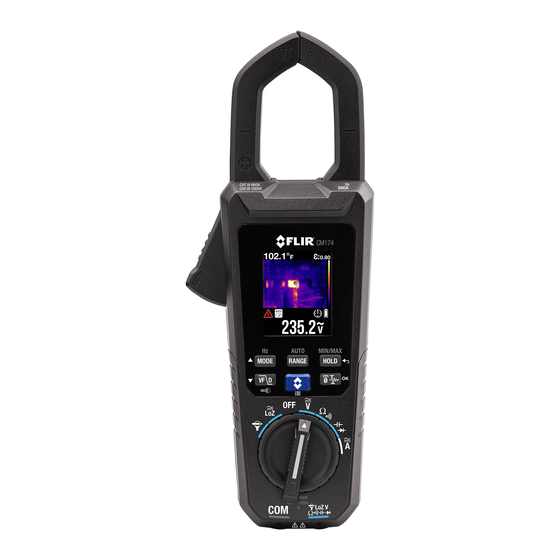
3. Introduction Thank you for selecting the FLIR CM174 Clamp Meter. The CM174 is a True RMS 600A AC/DC clamp meter with radiometric Lepton Thermal Imaging system, integrated VFD Mode, Inrush Current capture and a Lo Z mode for eliminating ‘ghost’ voltages. This device is shipped fully tested and calibrated and, with proper use, will provide years of reliable service. -
Page 8: Meter Description
12. Clamp jaw 1. Work light 2. Thermal imaging lens 3. Tripod mount 4. Warning & informational text 5. Battery compartment 6. Battery compartment lock 7. Laser pointer lens Fig 4-2 Rear View FLIR CM174 USER MANUAL Document Identifier: CM174-en-US_AC... -
Page 9: Function Switch
4.2 Function Switch Select this position when connecting a FLIR Flex Clamp Adaptor. Select this position to measure in the low impedance mode. Select this position to switch the meter OFF (full power saving mode). Select this position to measure AC/DC Voltage through the probe inputs. -
Page 10: Display Icons And Indicators
Ohm symbol. Unit of measure for Resistance and Continuity. Unit of measure for current (Amps or Amperes). Volt. Unit of measure for Voltage. Farad. Unit of measure for Capacitance. Hertz. Unit of measure for Frequency. 103 (kilo) 10-3 (milli) FLIR CM174 USER MANUAL Document Identifier: CM174-en-US_AC... - Page 11 10-6 (micro) VFD mode icon. DC Zero mode icon. Inrush current mode icon. FLEX Clamp Adaptor (FLIR TA72_TA74) icon. 100mV/Ampere Clamp Adaptor icon. Lo Z mode icon. ε Emissivity Bargraph Out of Range warning FLIR CM174 USER MANUAL Document Identifier: CM174-en-US_AC...
-
Page 12: Thermal Image Display
8. DCA Zero mode icon 9. Unit of measure 10. MIN reading 11. Battery status 12. Auto Power OFF (APO) 13. Data Hold icon 14. Auto Range icon Fig 4-4 Clamp Meter Display FLIR CM174 USER MANUAL Document Identifier: CM174-en-US_AC... -
Page 13: Operation
In Hold mode, the display freezes the last reading and continues to display this value. Use the HOLD button to toggle between Normal and Hold modes. In Hold mode, indicator is displayed. FLIR CM174 USER MANUAL Document Identifier: CM174-en-US_AC... -
Page 14: Voltage And Current Measurements
The low impedance is approx. 2.5kΩ. To take voltage measurements in the Lo Z mode, select the function switch position and follow the voltage measurement instructions in the previous section. FLIR CM174 USER MANUAL Document Identifier: CM174-en-US_AC... -
Page 15: Basic Current Measurements
5. Press the trigger to open the clamp jaws. Fully enclose one conductor—refer to Figure 5.2. For optimum results, center the conductor in the jaws. 6. Read the current value on the display. FLIR CM174 USER MANUAL Document Identifier: CM174-en-US_AC... -
Page 16: Extended Functionality Modes
5.4.4 Extended Functionality Modes In addition to the basic measurements that the CM174 can perform, a variety of extended functions are included. Refer to the following sections for details. 5.4.4.1 Inrush Current Mode In Inrush current mode, the meter displays the AC RMS current reading in the first 100ms period after the trigger point (current detection threshold) is reached, see Fig. - Page 17 The VFD mode is designed for such applications as variable frequency drives (VFD) and inverters. Press the VFD button to activate or deactivate the VFD mode. The VFD display icon is displayed when the mode is active. FLIR CM174 USER MANUAL Document Identifier: CM174-en-US_AC...
- Page 18 2. Connect the Flex Clamp as shown. 3. Set the range of the Flex Clamp adaptor to match the range of the CM174. For convenience, the CM174 will display the range setting (100mv/A). 4. Operate the Flex Clamp per instructions provided with the Flex Clamp meter.
-
Page 19: Resistance Measurements
3. Use the MODE button to select continuity measurement. The indicator will be displayed. 4. Touch the tips of the probe across the circuit or component under test. 5. If the resistance is lower than 30 Ω, the meter will beep. FLIR CM174 USER MANUAL Document Identifier: CM174-en-US_AC... -
Page 20: Capacitance Measurements
5. Read the capacitance value on the display. Note: For very large capacitance values, several seconds may be required for the measurement to settle and for the final reading to stabilize. Figure 5.6 Capacitance Measurements FLIR CM174 USER MANUAL Document Identifier: CM174-en-US_AC... -
Page 21: Diode Test (Classic Mode)
OL (overload) in the opposite direction, the component is good. If the measurement is 0V in both directions (shorted) or OL in both directions (open), the component is bad. Figure 5.7 Diode Testing FLIR CM174 USER MANUAL Document Identifier: CM174-en-US_AC... -
Page 22: Diode Test (Smart Mode)
6. If the reading is between ± 0.40 and +0.80V, the component is good; BAD or O.L displays indicate a defective component. In SMART Diode mode the CM174 checks diodes using an alternating test signal sent through the diode in both directions. This allows the user to check the diode without having to reverse polarity manually. -
Page 23: Igm Thermal Imager
30”, the meter ‘sees’ a target spot of 1”). See Fig 5-8 for examples. The thermal imager’s FOV (Field Of View) is 50 degrees (top view) and 38.6 degrees (side view), see Fig. 5-9 (a) and (b). FLIR CM174 USER MANUAL Document Identifier: CM174-en-US_AC... - Page 24 Imaging mode the electrical functions are shown on the lower portion of the display beneath the thermal image (see Fig. 5-8). Fig. 5-10 (a) Field of View – side view Fig. 5-10 (b) Field of View - top view FLIR CM174 USER MANUAL Document Identifier: CM174-en-US_AC...
-
Page 25: Programming Menu
ON or OFF Diode modes CLASSIC or SMART mode Auto Power OFF, 1, 2, 5, or 10 minutes Help Screen Contact and other useful information Information Firmware version, last calibration date, & laser information FLIR CM174 USER MANUAL Document Identifier: CM174-en-US_AC... - Page 26 3. Use the OK button to toggle C and F units. 4. When done, use the arrow buttons to continuing scrolling the Programming menu or use the Return button to exit the programming menu. FLIR CM174 USER MANUAL Document Identifier: CM174-en-US_AC...
- Page 27 2. Scroll to the information icon using the arrow buttons. 3. Press the OK button. 4. View the firmware version and the last calibration date. 5. Use the Return button to return to the Programming menu. FLIR CM174 USER MANUAL Document Identifier: CM174-en-US_AC...
-
Page 28: Infrared Energy And Imaging Theory
It may take some time to get used to the thermal imagery. Having a basic understanding of the differences between thermal and daylight cameras can help with getting the best performance from the CM174. One difference between thermal and daylight cameras has to do with where the energy comes from to create an image. - Page 29 ±2oC temperature change. 1. Definition from the imminent international adoption of DIN 54190-3 (Non-destructive testing – Thermographic testing – Part 3: Terms and definitions). FLIR CM174 USER MANUAL Document Identifier: CM174-en-US_AC...
-
Page 30: Maintenance
As with most electronic products, this equipment must be disposed of in an environmentally friendly way, and in accordance with existing regulations for electronic waste. Please contact your FLIR Systems representative for more details. FLIR CM174 USER MANUAL Document Identifier: CM174-en-US_AC... -
Page 31: Specifications
15.0 oz. (426g) including batteries Drop test: 6.6 ft. (2 meters) Agency Approvals: UL, CE, RCM, and KC (MSIP-REI-FS5-CM174) Over-voltage category: EN 61010-1 CAT IV-600 V, CAT III-1000 V, EN 61010-2-032 Application field Distribution circuits, machinery, main switching devices close to switchgears,... -
Page 32: Ir Thermal Imaging Specifications
7.2 IR Thermal Imaging Specifications Detector type FLIR LeptonTM; Micro-bolometer Focal Plane Array (FPA) Thermal Sensitivity 150mK IR Imaging resolution 60 x 80 pixels IR Imaging field of view 50.0 o x 38.6 o (vertical x horizontal) IR Imaging spectral response 8 to 14μm... -
Page 33: Electrical Specifications
For a crest factor of 1.0–2.0, add 3.0% to the accuracy. For a crest factor of 2.0–2.5, add 5.0% to the accuracy. For a crest factor of 2.5–3.0, add 7.0% to the accuracy. FLIR CM174 USER MANUAL Document Identifier: CM174-en-US_AC... - Page 34 >15V (rms) for ACV 10 kHz ~ 60 kHz >4A (rms) for ACA 10 Hz ~ 1 kHz >8A (rms) for ACA 1 kHz ~ 10 kHz Reading will be 0.0 for signals below 10.0 Hz FLIR CM174 USER MANUAL Document Identifier: CM174-en-US_AC...
- Page 35 > 150 Ω beeper off. Continuity indicator: 2.7 kHz tone buzzer. Continuity response time: <100 ms. Table 7.6 Capacitance Function Range Accuracy Capacitance 1 μF to 1000 μF ±(1.0% + 4 dgt) Overload protection: 1000 V (rms). FLIR CM174 USER MANUAL Document Identifier: CM174-en-US_AC...
-
Page 36: Technical Support
±(1% + 5 dgt) 45 ~ 400Hz 3000 A LCD displays ‘0’ counts when the reading is < 10 counts Additional accuracy for the Flex function is listed in the FLIR clamp adaptor User Manuals (Models TA72_TA74). Table 7.8 Flex Clamp Adaptor Function (Frequency) -
Page 37: Warranty
Purchaser, and for the cost of repackaging and returning the Product to Purchaser. Any non-warranty repair of a Product is warranted for one hundred eighty days (180) days from the date of return shipment by FLIR to be free from defects in materials and workmanship only, subject to all of the limitations, exclusions and disclaimers in this document. - Page 38 Corporate Headquarters FLIR Systems, Inc. 2770 SW Parkway Avenue Wilsonville, OR 97070 Telephone: +1 503-498-3547 Customer Support Technical Support Website http://support.flir.com Technical Support Email TMSupport@flir.com Service and Repair Email Repair@flir.com Customer Support Telephone +1 855-499-3662 option 3 (toll free) Publication Identification No.:...
Need help?
Do you have a question about the CM174 and is the answer not in the manual?
Questions and answers