Table of Contents
Advertisement
Quick Links
Advertisement
Table of Contents

Related Manuals for FLIR CM65


Summary of Contents for FLIR CM65
- Page 1 USER MANUAL True RMS 600A Solar Clamp Meter with METERLiNK® Model CM65...
- Page 3 USER MANUAL True RMS 600A Solar Clamp Meter with METERLiNK® #NAS100017; r. AB/59644/59644; en-US...
-
Page 5: Table Of Contents
Table of contents Advisories ................1 Copyright ..............1 Quality Assurance ............1 Documentation ............1 Disposal of Electronic Waste ......... 1 Introduction................2 Safety ................3 General Safety Information ........... 3 Safety Terms Used In This Manual ......... 3 Warning and Caution Statements ........3 UL Listing Note ............ - Page 6 Start/Stop a Data logging session......... 28 Deleting Data Log Files ..........28 Transmitting Data Log Files to a Mobile Device....28 Transferring Data Log Files to a PC....... 28 Viewing Data Log File Contents on the CM65 Display ..............28 USB Connectivity .............. 29 10.1 Field Firmware Updates ..........
- Page 7 Table of contents 12.16 Input Specifications........... 35 12.17 Safety Specifications ..........35 Three-Year Warranty ............37 Customer Support............. 38 14.1 Corporate Headquarters ..........38 #NAS100017; r. AB/59644/59644; en-US...
-
Page 9: Advisories
Advisories 1.1 Copyright ©2019, FLIR Systems, Inc. All rights reserved worldwide. No parts of the software including source code may be reproduced, transmitted, transcribed or translated into any language or computer language in any form or by any means, electronic, magnetic, optical, manual or otherwise, without the prior written permission of FLIR Systems. -
Page 10: Introduction
Introduction The CM65 is a 600 A True RMS Clamp Meter designed to meet the chal- lenges of the solar, alternative/renewable energies, and utilities industries. The supplied MC4 test leads help you troubleshoot photovoltaic systems and keep them running efficiently. The CM65 accurately measures voltage, current and other electrical parameters to ensure proper installation of PV systems. -
Page 11: Safety
Safety 3.1 General Safety Information This user manual contains information and warnings that must be followed for operating the instrument safely and maintaining the instrument in a safe oper- ating condition. If the instrument is used in a manner not specified by the man- ufacturer, the protection provided by the instrument may be impaired. -
Page 12: Ul Listing Note
Safety WARNING The accompanied test probe assembly meets UL/IEC/EN61010-031 Ed. 1.1 to 10A maxi- mum at 140℉ (60℃). IEC 61010-031 requires exposed conductive test probe tips to be ≤ 4 mm for CAT III & CAT IV ratings. Refer to the category markings on your probe assem- blies as well as on the add-on accessories (detachable Caps or Alligator Clips, etc.), if any, for applicable rating changes. -
Page 13: Cenelec Directives
Safety Double/reinforced insulation. Fuse. AC (alternating current). DC (direct current). Application around, and removal from, hazardous live conductors is permitted. 3.6 CENELEC Directives This instrument conforms to CENELEC Low-voltage directive 2014/35/EC, Electromagnetic compatibility directive 2014/30/EU and RoHS directive 2011/ 65/EU. #NAS100017;... -
Page 14: Descriptions
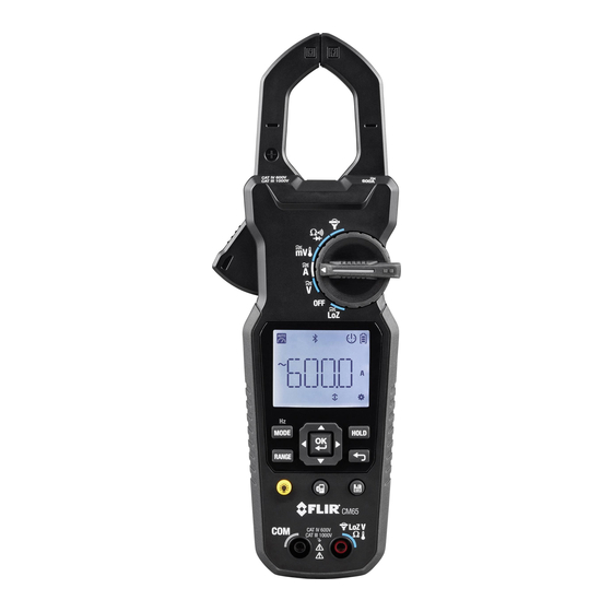
Descriptions 4.1 Product Description Figure 4.1 Product Description 1. Clamp jaws 2. Clamp measurement area 3. Jaw opening trigger 4. Display area 5. OK menu button (center) and navigation arrows 6. MODE/Hz button 7. RANGE button 8. Display backlight button 9. -
Page 15: Control Button Descriptions
Descriptions Note: Battery compartment on rear, not pictured. USB port located inside bat- tery compartment. 4.2 Control Button Descriptions Toggle AC/DC (short presses), select frequency (Hz) mode (long press), select an option at a multi-option rotary switch position. Short press for Manual range mode, long press to return to Auto. Short press to freeze/unfreeze displayed readings. -
Page 16: Display Description
Descriptions 4.4 Display Description Figure 4.2 Display Icon Descriptions 1. Auto Range 2. MAX/MIN/AVG memory 3. Data Hold 4. Bluetooth® 5. Data logger 6. Prompt to use up/down arrow buttons 7. Auto Power OFF (APO) 8. Battery status 9. AC measurements 10. -
Page 17: Meter Operation
Meter Operation CAUTION Before operating the device, you must read, understand, and follow all instructions, dan- gers, warnings, cautions, and notes. NOTE When the meter is not in use, the function switch should be set to the OFF position. CAUTION When connecting the probe leads to the device under test, connect the negative lead be- fore connecting the positive lead. -
Page 18: Out-Of-Range Alert
Meter Operation Figure 5.1 Auto Range Display Icon 5.4 Out-of-Range Alert If the input is out-of-range, OL is displayed. Please do not attempt to make measurements beyond the specified ranges of the meter. 5.5 Display Hold Function After taking a measurement, short press the HOLD button to freeze a reading. Press the HOLD button again to return to normal operation. -
Page 19: Loz Voltage Measurements
Meter Operation Figure 5.2 Basic Voltage Measurement Setup 1. Set the function switch to the Voltage position 2. Short press the MODE button to select AC or DC voltage mode. 3. Insert the black test lead into the negative (COM) terminal and the red test lead into the positive terminal. -
Page 20: Low Pass Filter (Vfd) Voltage Measurements
Use caution when the measured voltage is greater than 30V DC or AC rms. The VFD feature in the CM65 eliminates high frequency noise in AC voltage measurements by means of a low pass filter. The VFD mode is designed for variable frequency drive measurements. -
Page 21: Current Measurements (Clamp)
Meter Operation Figure 5.3 Millivolt Measurements 1. Set the function switch to the millivolt position 2. Short press the MODE button to select AC or DC voltage mode. 3. Insert the black test lead into the negative (COM) terminal and the red test lead into the positive terminal. - Page 22 Meter Operation WARNING Do not use the meter to measure current above the rated frequency. This may cause the magnetic circuits in the jaws to reach hazardous temperatures. WARNING Disconnect the test leads from the meter before taking Clamp measurements. Clamp Measurement Considerations •...
-
Page 23: Resistance Measurements
Meter Operation 2. Short press the MODE button to select AC or DC current mode. 3. For DC current mode, with no conductor in the clamp, use the DC Zero menu icon to zero the display (see the Function Icons section for complete details). -
Page 24: Continuity Measurements
Meter Operation 2. If necessary, short press the MODE button to select the Resistance func- tion k . 3. Insert the black test lead into the negative (COM) terminal and the red test lead into the positive terminal. 4. Place the probe ends of the test leads in parallel to the part under test. 5. -
Page 25: Diode Measurements
Meter Operation 3. Insert the black test lead into the negative (COM) terminal and the red test lead into the positive terminal. 4. Place the probe ends of the test leads in parallel to the part under test. 5. If the measurement is <30 Ω, the meter will beep. If the measurement is > 480Ω, the meter will not beep. -
Page 26: Type-K Thermocouple Measurements
Meter Operation 4. Take two diode measurements, one in forward bias and one in reverse bias. This can be accomplished by, first, placing the probe ends of the test leads in parallel to the part under test in one direction and then taking a second measurement in the reverse polarity orientation. - Page 27 Meter Operation Figure 5.8 Thermocouple Temperature Measurements 1. Set the function switch to the Temperature position . 2. Use the MODE button to select the Temperature mode. 3. Insert the banana plug Type-K temperature probe into the meter’s input terminals observing correct polarity. A plug adapter with banana plug to Type-K socket (to adapt to other Type-K standard mini plug temperature probes) can be obtained optionally.
-
Page 28: External Clamp Adaptor Current Measurements
Figure 5.9 External Clamp Adaptor Test Setup 1. Set the CM65 function switch to the external clamp adaptor position 2. Connect the external clamp adaptor to the CM65 by inserting the signal leads from the external clamp to the input terminals on the CM65, observ- ing correct polarity. -
Page 29: Bluetooth® Communication And Flir Tools
LiNK® protocol) continually sends readings for live display on the remote de- vice. The CM65 can also transmit bulk data log files to a mobile device (see Section 9, Data logging, and Section 7, Function Icons, to learn about these features). - Page 30 Bluetooth® Communication and FLIR Tools™ 3. Connect the equipment into an outlet on a circuit different from that to which the receiver is connected. 4. Consult the dealer or an experienced radio/TV technician for help. WARNING Changes or modifications not expressly approved by the party responsible for compliance could void the user’s authority to operate the equipment.
-
Page 31: Function Icons
OK, this will erase the selected file (see icon at the beginning of this section). • Data Log File Open To view the logged readings of a file directly on the CM65 display, see the steps below: #NAS100017; r. AB/59644/59644; en-US... - Page 32 5. To exit this mode (and to reset the Max/Min/Avg memories), press the Return button. • DC Zero 1. This icon is available in the DC current mode. When selected, the CM65 display zeros so you can take an accurate DC clamp meter measurement. #NAS100017; r. AB/59644/59644; en-US...
- Page 33 Function Icons 2. When this icon is available, scroll to it with the left/right arrow buttons until the icon is blinking. 3. Press OK at the blinking icon to engage the mode and the display will zero. 4. To exit this mode, press the Return button. •...
-
Page 34: Programming Menu
Programming Menu To access the CM65 Programming Menu, short press the OK button with the meter ON (or select the Settings function icon as explained in Section 7, Function Icons). Use the up/down arrow buttons to scroll the Programming Menu list and press OK at a parameter to open it. See the details below: •... - Page 35 Programming Menu 6. Press OK to confirm the month and date. 7. Use the up/down arrows to set the hours. 8. Use the right arrow to select the minutes digits and use the up/down ar- rows to set the minutes. 9.
-
Page 36: Data Logging
Section 7, Function Icons, for complete details. 9.4 Transmitting Data Log Files to a Mobile Device The CM65 can transmit Data Log files to a paired mobile device using the Da- ta Log File Transmit function icon . Please read the paragraph Data Log File Transmit in Section 7, Function Icons, for complete details. -
Page 37: Usb Connectivity
The USB port in the battery compartment allows for field firmware updates, follow the steps below. 1. Connect the CM65 to a PC using a USB cable. The CM65 USB port is lo- cated in the battery compartment. 2. Turn the CM65 rotary switch to any position, the CM65 will display ‘USB’. -
Page 38: Maintenance
Maintenance 11.1 Cleaning With the CM65 OFF, wipe the meter housing with a damp cloth as needed. Do not use abrasives or solvents. Dry completely before use. 11.2 Battery Replacement The battery compartment is located on the back of the CM65. Use a small screwdriver to turn the battery compartment lock so that the arrow printed on the battery compartment cover is pointing toward the ‘open lock’... -
Page 39: Specifications
Specifications 12.1 General Specifications Display 6000 count backlit LCD Polarity Automatic Update rate 5 readings per second, nominal Operating temperature 32 ~ 140℉ (0 ~ 60℃) Relative humidity Maximum relative humidity 80% for temper- ature up to 88℉ (31℃) decreasing linearly to 50% relative humidity at 122℉... -
Page 40: Dc Voltage Specifications
Specifications 12.2 DC Voltage Specifications Range and Resolution Accuracy 60.00 V ± (1% + 2 digits) 600.0 V 1000 V Input Impedance: 10MΩ, 100 pF nominal Safety Category Rating: CAT III 1000 V & CAT IV 600 V DC 12.3 DC mV Specifications Range and Resolution Accuracy 60.00 mV... -
Page 41: Loz Voltage Ac And Dc Specifications
Specifications 12.7 LoZ Voltage AC and DC Specifications Range and Resolution Frequency Accuracy 45Hz ~ 440Hz ± (2.0% + 3 digits) 60.00 V /600.0 V /1000 V For inputs < 50 V, the impedance is 2.3 kΩ. For inputs > 50 V, the initial impe- dance is 2.3 kΩ... -
Page 42: Resistance Specifications
Specifications 50 ~ 100 Hz ± (1.5% + 5 digits) 600.0 A 0.1 A 100 ~ 400 Hz ± (2.0% + 5 digits) Induced error from adjacent current-carrying conductors: < 0.1A/A Safety Category Rating: CAT III 1000 V & CAT IV 600 V AC 12.11 Resistance Specifications Range Resolution... -
Page 43: Temperature Specifications
Specifications 30.00 A (100mV/A) 300.0 A (10mV/A) 45~ 440 Hz (sine wave) ± (2.0% + 3 digits)* 3000A (1mV/A) *Does not include error introduced by the external clamp adaptor. 12.15 Temperature Specifications Range Accuracy -40.0 ~ 752℉ ± (1.0% + 2℉) -40.0 ~ 400℃... - Page 44 Specifications Drop-proof Designed to 3.3 ft. (1 m) EN 61000-6-3 EN 61000-6-2 FCC 47 CFR Part 15 Class B #NAS100017; r. AB/59644/59644; en-US...
-
Page 45: Three-Year Warranty
Three-Year Warranty Please register your product within 60 days of purchase. Register your prod- uct at https://support.flir.com/prodreg or use the QR Code. Read the warranty text at the links provided. Figure 13.1 Product Registration QR Code #NAS100017; r. AB/59644/59644; en-US... -
Page 46: Customer Support
Customer Support Repair, Calibration, and Technical Support: https://support.flir.com. 14.1 Corporate Headquarters FLIR Systems, Inc. 27700 SW Parkway Avenue Wilsonville, OR 97070, USA #NAS100017; r. AB/59644/59644; en-US... - Page 48 Customer support http://support.flir.com Copyright © 2019, FLIR Systems, Inc. All rights reserved worldwide. Disclaimer Specifications subject to change without further notice. Models and accessories subject to regional market considerations. License procedures may apply. Products described herein may be subject to US Export Regulations.
Need help?
Do you have a question about the CM65 and is the answer not in the manual?
Questions and answers