
Related Manuals for FLIR CM72


Summary of Contents for FLIR CM72
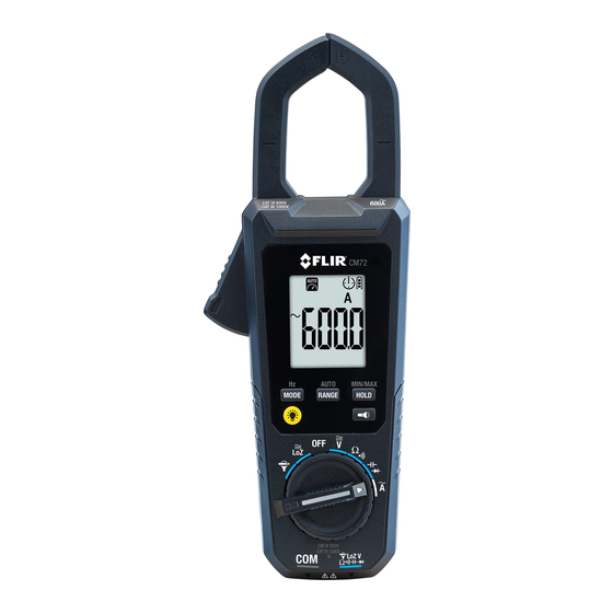
- Page 1 USER MANUAL FLIR CM72 and CM74 CLAMP METERS CM72 600A True RMS AC Clamp Meter CM74 600A True RMS AC/DC Clamp Meter ...
-
Page 2: Table Of Contents
4. METER DESCRIPTION 8 4.1 Meter Parts 4.2 Function Switch 4.3 Function Buttons 4.4 Display Icons and Indicators 5. OPERATION 12 5.1 Powering the Meter 5.1.1 Auto Power Off 5.2 Auto/Manual Range Mode 5.3 HOLD Mode 5.4 Voltage and Current Measurements 5.4.1 Basic Voltage Measurements 5.4.2 ‘Lo Z’ Voltage Measurements 5.4.3 Basic Current Measurements 5.4.4 Extended Functionality Modes 5.4.4.1 Inrush Current Mode (CM74 only) 5.4.4.2 DCA Zero Mode (CM74 only) 5.4.4.3 Frequency Mode 5.4.4.4 MIN/MAX Mode FLIR CM72_CM74 USER MANUAL Document Identifier: CM72_CM74‐en‐US_AA ... - Page 3 5.4.4.5 VFD Mode (low pass filter) CM74 only 5.4.4.6 Flex Clamp Adaptor Use 5.5 Resistance Measurements 5.6 Continuity Test 5.7 Capacitance Measurements 5.8 Diode Test 6. MAINTENANCE 21 6.1 Cleaning and Storage 6.2 Battery Replacement 7. SPECIFICATIONS 22 7.1 General specifications 7.2 Electrical specifications 8. TECHNICAL SUPPORT 28 9. WARRANTIES 28 9.1 FLIR Global Limited Lifetime Warranty FLIR CM72_CM74 USER MANUAL Document Identifier: CM72_CM74‐en‐US_AA ...
-
Page 4: Disclaimers
1. Disclaimers 1.1 Copyright © 2015, FLIR Systems, Inc., All rights reserved worldwide. No parts of the software including source code may be reproduced, transmitted, transcribed or translated into any language or computer language in any form or by any means, electronic, magnetic, optical, manual or otherwise, without the prior written permission of FLIR Systems. The documentation must not, in whole or part, be copied, photocopied, reproduced, translated or transmitted to any electronic medium or machine readable form without prior consent, in writing, from FLIR Systems. Names and marks appearing on the products herein are either registered trademarks or trademarks of FLIR Systems and/or its subsidiaries. All other trademarks, trade names or company names referenced herein are used for identification only and are the property of their respective owners. 1.2 Quality Assurance The Quality Management System under which these products are developed and manufactured has been certified in accordance with the ISO 9001 standard. FLIR Systems is committed to a policy of continuous development; therefore we reserve the right to make changes and improvements on any of the products without prior notice. 1.3 Documentation To access the latest manuals and notifications, go to the Download tab at: http://support.flir.com. It only takes a few minutes to register online. In the download area you will also find the latest releases of manuals for our other products, as well as manuals for our historical and obsolete products. 1.4 Disposal of Electronic Waste As with most electronic products, this equipment must be disposed of in an environmentally friendly way, and in accordance with existing regulations for electronic waste. Please contact your FLIR Systems representative for more details. FLIR CM72_CM74 USER MANUAL Document Identifier: CM72_CM74‐en‐US_AA ... -
Page 5: Safety
2. Safety Safety Notes Before operating the device, you must read, understand, and follow all instructions, dangers, warnings, cautions, and notes. FLIR Systems reserves the right to discontinue models, parts or accessories, and other items, or to change specifications at any time without prior notice. Remove the batteries if the device is not used for an extended period of time. Warning Statements Do not operate the device if you do not have the correct knowledge. Formal qualifications and/or national legislation for the electrical inspections can apply. Incorrect operation of the device can cause damage, shock, injury or death to persons. Do not start the measuring procedure before you have set the function switch to the correct position. This can cause damage to the instrument and can cause injury to persons. Do not change to current or resistance when you measure the voltage. This can cause damage to the instrument and can cause injury to persons. Do not measure the current on a circuit when the voltage increases to more than 1000 V. This can cause damage to the instrument and can cause injury to persons. You must disconnect the test leads from the circuit that you did a test on before you change the range. If you do not do this, damage to the instrument and injury to persons can occur. Do not replace the batteries before you remove the test leads. This can cause damage to the instrument and can cause injury to persons. Do not use the device if the test leads and/or the device show signs of damage. Injury to persons can occur. Be careful when taking measurements if the voltages are more than 25 VAC rms or 35 VDC. There is a risk of shock from these voltages. Injury to persons can occur. Do not do diode, resistance or continuity tests before you have removed the power from capacitors and other devices under test during a measurement. Injury to persons can occur. ... - Page 6 Cautions Do not use the device for a procedure that it is not intended for. This can cause damage to the protection. This symbol, adjacent to another symbol or terminal, indicates that the user must refer to the manual for further information. This symbol, adjacent to a terminal, indicates that, under normal use, hazardous voltages may be present. Double insulation. UL listing is not an indication or a verification of the accuracy of the meter FLIR CM72_CM74 USER MANUAL Document Identifier: CM72_CM74‐en‐US_AA ...
-
Page 7: Introduction
3. Introduction Thank you for selecting the FLIR CM72_CM74 Clamp Meter. The CM72 is a True RMS 600A AC Clamp Meter and the CM74 is a True RMS 600A AC/DC clamp meter with integrated VFD Mode, Inrush Current capture. Both meters have a Lo Z mode for eliminating ‘ghost’ voltages. This device is shipped fully tested and calibrated and, with proper use, will provide years of reliable service. 3.1 Key Features 6000‐count digital display Large‐scale 2.0” backlit display Work light Auto Range True RMS AC 600 A capability and selection CM72 Auto Range True RMS AC/DC 600 A capability and selection CM74 Auto Range True RMS AC/DC 600 V capability and selection Frequency AC bandwidth (45‐400Hz) Frequency Measurements to 60KHz Flex Clamp adaptor input for FLIR TA72_TA74 Clamp adaptors Resistance and Continuity measurements Capacitance and Diode measurements Data hold Inrush current (CM74 only) DCA zero function (CM74 only) Low Z (Impedance) mode for both models CM72 and CM74 ... -
Page 8: Meter Description
4. Meter Description 4.1 Meter Parts Fig 4‐1 Front View Jaw opening trigger Hz‐MODE button Backlight/Work light button (CM74); Backlight button only (CM72) Function switch COM (negative ‐) Probe Input jack Positive (+) Probe Input jack DCA Zero and Inrush button (CM74 only) Work light button (CM72) MIN/MAX HOLD button AUTO‐RANGE Button 10. LCD Display 11. Clamp jaw Fig 4‐2 Rear View Work light Tripod mount Warning text Battery compartment Battery compartment lock FLIR CM72_CM74 USER MANUAL Document Identifier: CM72_CM74‐en‐US_AA ... -
Page 9: Function Switch
4.2 Function Switch Select this position when connecting a FLIR Flex Clamp Adaptor. Select this position to measure in the low impedance mode. Select this position to switch the meter OFF (full power saving mode). Select this position to measure AC/DC Voltage through the probe inputs. The meter can measure resistance and continuity through the probe inputs. The type of measurement is selected by the MODE button. The meter can measure capacitance and diode through the probe inputs. The type of measurement is selected by the MODE button. Amps AC/DC (CM74) and Amps AC only (CM72). The meter can measure current through the clamp jaws. 4.3 Function Buttons Select AC or DC in the Voltage/Current modes. Select Diode or Capacitance; Continuity or Resistance. Select Hz in the AC Voltage/Current/FLEX modes. Select Auto or Manual range mode, see section 5.3 Auto/Manual range mode In Manual mode, press to change the range (scale); to return to Auto range mode from Manual mode, press and hold for > 2 seconds. Toggle normal and Hold modes, see section 5.4 Hold mode Press for > 2 seconds to enable/disable MIN/MAX mode. While in MIN/MAX mode, short presses step MIN>MAX>MIN. Press and hold for >2 seconds to exit the MIN/MAX mode. For the CM74: Press to enable/disable the display backlight. Press and hold for > 2 seconds to switch the Work Light ON/OFF. For the CM72 press to enable/disable the LCD backlight. For the CM72 press to enable/disable the Work Light. For the CM74 only. In the DCA mode, press to zero the display. In the ACA mode press to enable the inrush current mode. ... -
Page 10: Display Icons And Indicators
4.4 Display Icons and Indicators Fig 4‐3 Display Icons Refer to Fig. 4-3 above for the display icon descriptions below: Indicates that the meter is displaying maximum reading values. Indicates that the meter is displaying minimum reading values. Indicates that the meter is in Auto range mode. Indicates that the meter is in Hold mode. Indicates the battery voltage status. Indicates that the auto power off function is enabled. Indicates that the measured voltage is greater than 30 V DC or AC RMS. Indicates that the meter is measuring AC current or voltage. Indicates that meter is measuring DC current or voltage (DCA CM74 only). Indicates that the continuity function is active. Indicates that the diode test function is active. Ohm symbol. Unit of measure for Resistance and Continuity. FLIR CM72_CM74 USER MANUAL Document Identifier: CM72_CM74‐en‐US_AA ... - Page 11 Unit of measure for current (Amps or Amperes). Volt. Unit of measure for Voltage. Farad. Unit of measure for Capacitance. Hertz. Unit of measure for Frequency. (kilo) ‐3 (milli) ‐6 (micro) VFD mode icon (CM74 only). DC Zero mode icon (CM74 only). Inrush current mode icon (CM74 only). Flex Clamp Adaptor (FLIR TA72_TA74) icon. 100mV/Ampere Clamp Adaptor icon. Lo Z mode icon. 4.4.1 Out‐of‐range Warning If the input is out‐of‐range, OL is displayed. FLIR CM72_CM74 USER MANUAL Document Identifier: CM72_CM74‐en‐US_AA ...
-
Page 12: Operation
5. Operation Note: Before operating the device, you must read, understand, and follow all instructions, dangers, warnings, cautions, and notes. Note: When the meter is not in use, the function switch should be set to the OFF position. Note: When connecting the probe leads to the device under test, connect the negative lead before connecting the positive lead. When removing the probe leads, remove the positive lead before removing the negative lead. 5.1 Powering the Meter 1. Set the function switch to any position to switch the meter ON. 2. If the battery indicator shows that the battery voltage is low or if the meter does not power on, replace the batteries. See section 6.2 Battery replacement. 5.1.1 Auto Power Off The meter enters sleep mode after 10 minutes of inactivity. The meter beeps three times before powering off. Press any button or turn the function switch to prevent the meter from powering off. The auto power off time‐out is then reset. To disable auto power off press the MODE button while turning the meter ON. The APO icon is displayed when APO is active. 5.2 Auto/Manual Range Mode In Auto range mode, the meter automatically selects the most appropriate measurement scale. In Manual range mode, the desired range (scale) can be set manually. Auto range mode is the default mode of operation. When a new function is selected with the function switch, the starting mode is Auto range and the indicator is displayed. To enter Manual range mode, press the RANGE button. To change the range, press the RANGE button repeatedly until the desired range is displayed. To return to Auto range mode from Manual mode, press and hold the RANGE button until the indicator is displayed. 5.3 HOLD Mode In Hold mode, the display freezes the last reading and continues to display this value. Press the HOLD button to toggle between Normal and Hold modes. In Hold mode, the indicator is displayed. FLIR CM72_CM74 USER MANUAL Document Identifier: CM72_CM74‐en‐US_AA ... -
Page 13: Voltage And Current Measurements
5.4 Voltage and Current Measurements Note: If the measured voltage is greater than 30 V DC or AC RMS, the indicator is displayed. 5.4.1 Basic Voltage Measurements Set the function switch to the V position. To manually select AC or DC, press the MODE button. To manually select the measurement range (scale), press the RANGE button repeatedly. Refer to section 5.2 Auto/Manual range mode. Insert the black probe lead into the negative COM terminal and the red probe lead into the positive V terminal. Connect the probe leads in parallel to the part under test. Read the voltage value on the display. Figure 5.1 Voltage Measurements 5.4.2 ‘Lo Z’ Voltage Measurements When the function switch is turned to the position, the meter incorporates a low impedance circuit that eliminates ghost voltages. The low impedance is approx. 2.5kΩ. To take voltage measurements in the Lo Z mode, select the function switch position and follow the voltage measurement instructions in the previous section. FLIR CM72_CM74 USER MANUAL Document Identifier: CM72_CM74‐en‐US_AA ... -
Page 14: Basic Current Measurements
5.4.3 Basic Current Measurements WARNING Do not measure the current on a circuit when the voltage increases to more than 600V (CM72) or 1000V (CM74). This can cause damage to the instrument and can cause injury to persons. When measuring current using the clamp jaws, only one conductor should be enclosed by the jaws—refer to Figure 5.2. Figure 5.2 Correct and incorrect setup Ensure that the probe leads are disconnected from the meter. Set the function switch to the A position. To manually select AC or DC press the MODE button repeatedly. DCA is only available on the CM74. To manually select the measurement range (scale), press the RANGE button repeatedly. Refer to section 5.3 Auto/Manual range mode. Press the trigger to open the clamp jaws. Fully enclose one conductor—refer to Figure 5.2. For optimum results, center the conductor in the jaws. Read the current value on the display. FLIR CM72_CM74 USER MANUAL Document Identifier: CM72_CM74‐en‐US_AA ... -
Page 15: Extended Functionality Modes
5.4.4 Extended Functionality Modes In addition to the basic measurements that the CM72 and CM74 can perform, a variety of extended functions are included. Refer to the following sections for details. 5.4.4.1 Inrush Current Mode (CM74 only) In Inrush current mode, the meter displays the highest AC current reading in the first 100ms period after the trigger point (current detection threshold) is reached, see Fig. 5.3 below. The current detection threshold is 0.5A for the 60.00A range and 5.0A for the 600.0A range. Inrush current mode is available when measuring AC current. Connect the meter to the unpowered circuit under test Set the meter to A Press the Inrush button to enable the Inrush current mode. The Inrush display icon will appear on the LCD. Turn on the power to the circuit under test When the threshold is reached, the meter will display the RMS reading for the 100ms integration time. Measured Inrush Current Current Detection Threshold TIME 100ms Sample Window (60Hz) ... -
Page 16: Dca Zero Mode (Cm74 Only)
Press the DCA Zero button to enable DC Zero. The display will zero. 5.4.4.3 Frequency Mode In Frequency mode, the meter measures and displays the frequency. Frequency mode is available when measuring AC current or voltage. Important note: Do not switch to the Frequency mode until the meter is setup and actively measuring the voltage or current signal. Press and hold the MODE button to select and enable Frequency mode. 5.4.4.4 MIN/MAX Mode In MIN/MAX mode, the meter captures and displays the Minimum and Maximum readings and updates only when a higher/lower value is registered. Press and hold the HOLD button to access the MIN/MAX mode. The first screen will be the MIN screen. The down arrow will appear (indicating MIN mode) and the displayed reading will represent the lowest reading encountered since the HOLD button was first pressed. Press the HOLD button again; this next screen will be the MAX display. The up arrow will appear (indicating MAX mode) and the displayed reading will represent the highest reading encountered since the HOLD button was first pressed. Continue to use the HOLD button to toggle the MIN/MAX readings as desired. Press and hold the HOLD button for 2 seconds to exit the MIN/MAX mode. The meter will return to normal operation and the MIN/MAX memories will be reset. 5.4.4.5 VFD Mode (low pass filter) CM74 only The VFD mode eliminates high frequency noise in voltage measurements by means of a low‐pass filter. The VFD mode is designed for variable frequency drive (VFD) measurements. This mode is always active for AC measurements. The VFD display icon is always displayed when AC Current or AC Voltage modes are selected. FLIR CM72_CM74 USER MANUAL Document Identifier: CM72_CM74‐en‐US_AA ... -
Page 17: Flex Clamp Adaptor Use
5.4.4.6 Flex Clamp Adaptor Use A FLIR Clamp Adaptor (Models TA72 and TA74) can be connected to the CM72 or CM74 to display current measurements made by the FLEX Clamp Adaptor. Turn the function dial to the position. Connect the Flex Clamp as shown. Set the Range of the Flex Clamp Adaptor to match the range of the CM174. Operate the Flex Clamp per instructions provided with the Flex Clamp meter. Read the current measured by the Flex Clamp on the CM72 or CM74 LCD. Figure 5.4 Connecting a FLIR Flex Clamp Adaptor FLIR CM72_CM74 USER MANUAL Document Identifier: CM72_CM74‐en‐US_AA ... -
Page 18: Resistance Measurements
Set the function switch to the position. Use the MODE button to select the resistance mode (continuity symbol should be OFF). Insert the black probe lead into the negative COM terminal and the red probe lead into the positive Ω terminal. Touch the tips of the probe across the circuit or component under test. Read the resistance value on the display. Figure 5.5 Resistance and Continuity Measurements 5.6 Continuity Test Warning: Do not perform continuity tests before removing the power to the component, circuit, or other device under test during a measurement. Injury to persons can occur. Set the function switch to the position. Insert the black probe lead into the negative COM terminal and the red probe lead into the positive Ω terminal. Refer to Fig. 5‐5 for connection example. Use the MODE button to select continuity measurement. The indicator will be displayed. Touch the tips of the probe across the circuit or component under test. If the resistance is lower than 30 Ω, the meter will beep. FLIR CM72_CM74 USER MANUAL Document Identifier: CM72_CM74‐en‐US_AA ... -
Page 19: Capacitance Measurements
5.7 Capacitance Measurements Warning: Do not perform capacitance tests before removing the power to the capacitor or to other devices under test during a measurement. Injury to persons can occur. Set the function switch to the position. Use the MODE button to select capacitance function (capacitor symbol must be displayed). Insert the black probe lead into the negative COM terminal and the red probe lead into the positive terminal. Touch the tips of the probe across the part under test. Read the capacitance value on the display. Note: For very large capacitance values, several seconds may be required for the measurement to settle and for the final reading to stabilize. Figure 5.6 Capacitance Measurements FLIR CM72_CM74 USER MANUAL Document Identifier: CM72_CM74‐en‐US_AA ... -
Page 20: Diode Test
5.8 Diode Test Warning: Do not perform diode tests before removing the power to the diode or other devices under test during a measurement. Injury to persons can occur. Set the function switch to the diode position. Insert the black probe lead into the negative COM terminal and the red probe lead into the positive Ω terminal. Use the MODE button to select the diode test function. The diode indicator will be displayed. Touch the tips of the probe across the diode or semiconductor junction under test. If the reading is between 0.40 and 0.80V in one direction and OL (overload) in the opposite direction, the component is good. If the measurement is 0V in both directions (shorted) or OL in both directions (open), the component is bad. Figure 5.7 Diode Tests FLIR CM72_CM74 USER MANUAL Document Identifier: CM72_CM74‐en‐US_AA ... -
Page 21: Maintenance
6. Maintenance 6.1 Cleaning and Storage Clean the meter with a damp cloth and mild detergent; do not use abrasives or solvents. If the meter is not to be used for an extended period, remove the batteries and store them separately. 6.2 Battery Replacement To avoid electrical shock, disconnect the meter if connected to a circuit, remove the probe leads from the terminals, and set the function switch to the OFF position before attempting to replace the batteries. Unlock and remove the battery compartment cover. Replace the four (4) standard AAA batteries, observing correct polarity. Secure the battery compartment cover. 6.2.1 Disposal of Electronic Waste As with most electronic products, this equipment must be disposed of in an environmentally friendly way, and in accordance with existing regulations for electronic waste. Please contact your FLIR Systems representative for more details. FLIR CM72_CM74 USER MANUAL Document Identifier: CM72_CM74‐en‐US_AA ... -
Page 22: Specifications
7. Specifications 7.1 General specifications Display counts: 0~6000 Measuring rate: 3 times per second Over‐range indication: OL or –OL. Auto power off: 10 minutes (can be disabled) Low battery indicator: is displayed. Replace battery when indicator appears. Power requirement: 4 × 1.5 V AAA alkaline batteries. Battery life: Approx. 200 hours for CM72; 100 hours for CM74 (with alkaline batteries and backlight/work light off) Calibration: 1 year calibration cycle. Operating conditions: 14 to 50°F (‐10 to 10°C) (non‐condensing) ≤ 50 to 86°F (10 to 30°C) ( 80% RH) ≤ 86 to 104°F (30 to 40°C) ( 75% RH) ≤ 104 to 122°F (40 to 50°C) ( 45%RH) Storage conditions: 4 to 140°F (‐20 to 60°C); 0–80% RH (batteries not installed) Dimensions: ... -
Page 23: Electrical Specifications
° ° ° Accuracy is ± (% reading + number of digits (dgt)) at 73.4 F ±9 F (23 C ±5 C), <80% RH. Table 7.1 Voltage (TRMS) Function Range Accuracy (of reading) 60.00 V DCV 600.0 V ± (1.0% + 5 dgt) 1000 V (CM74) 60.00 V ± (1.0% + 5 dgt) ACV 600.0 V (CM72) 45~400 Hz 1000 V (CM74) 60.00 V ± (1% + 5 dgt) 45~65 Hz ACV VFD (CM74 only) 600.0 V ± (5% + 5 dgt) 65~400Hz 1000 V 60.0V AC/DC AC: ± (1.0% + 5 dgt) 45~400 Hz 600.0V AC/DC Lo Z (Low Impedance) (CM72) DC: ± (1.0% + 5 dgt) 1000V AC/DC (CM74) ... - Page 24 DCA (CM74 only) ± (2% + 5 dgt) 600.0 A 60.00 A ± (2% + 5dgt) 45~65Hz ± (2% + 5dgt) 65~400Hz 600.0 A for CM74 ACA ± (2% + 5dgt) 45~65Hz ± (3% + 5dgt) 65~400Hz for CM72 60.00 A ACA VFD ± (2% + 5 dgt) 45~65Hz (CM74 only) ± (6% + 5 dgt) 65~400Hz 600.0 A Notes: CM72: No VFD Mode and ACA Only CM74: Integrated VFD Mode always ON in ACA MODE Overload protection: 600A (rms) Position Error: ±1% of reading for CM74 (CM72 not specified). AC Conversion Type and additional accuracy is same as AC Voltage. DCA affected by the temperature and residual magnetism; use DCA Zero function to compensate. AC conversion type: AC coupled, true RMS responding, calibrated to the RMS value of a sine wave input. Accuracies are given for sine waves at full scale and non‐sine waves below half scale. If the meter measures a 4000‐count signal and the Crest Factor of the signal is more then 3.0, the reading may not meet specified tolerances. For non‐sine waves (50/60 Hz), add the following Crest Factor corrections: For non‐sine waves (50/60 Hz), add the following crest factor corrections: ...
- Page 25 Table 7.3 Frequency Accuracy Function Range 600.0 Hz Frequency 6.000 kHz ± (0.1% + 2 dgt) 60.00 kHz Notes: These frequency specifications also apply to ‘Lo Z’ Frequency measurements Overload protection: CM72: 600Vrms and 600 A (rms) CM74: 1000Vrms and 600 A (rms) ; Trigger Sensitivity: >5Vrms for ACV 10Hz~10kHz >15Vrms for ACV 10kHz~60kHz range >4Arms for ACA 10Hz~10kHz >8Arms for ACA 1kHz~10kHz (CM74 only) Reading will be 0.0 for signals below 10.0 Hz. Table 7.4 Inrush current (CM74 only) Function Range Accuracy 60.00 A ±(3% + 0.3 A) ACA inrush 600.0 A ±(3% + 5 dgt) Inrush current detection threshold: 0.5A for 60A range and 5.0A for 600.0A range Overload protection: 1000 V rms , 600 A ( rms) ...
- Page 26 Table 7.5 Resistance and continuity and diode Function Range Accuracy 600.0 Ω (CM74 only) Resistance ±(1.0% + 5 dgt) 6000 Ω (6.000kΩ for CM74) Continuity 600.0 Ω ±(1.0% + 5 dgt) Diode 1.5V ±(1.5% + 5 dgt) CM72 Overload protection: 600 V ( rms) . CM74 Overload protection: 1000 V ( rms) . Maximum test current: Approx. 0.1 mA. Maximum open circuit voltage for Ω: Approx. 1.8 V. Maximum open circuit voltage for diode: Approx. 1.8 V. Continuity threshold: < 30 Ω beeper on; > 150 Ω beeper off. Continuity indicator: 2.7 kHz tone buzzer. Continuity response time: <100 ms. Table 7.6 Capacitance Function Range Accuracy Capacitance 1 μF to 1000 μF ±(1.0% + 4 dgt) CM72 Overload protection: 600 V ( rms) . CM74 Overload protection: 1000 V ( rms) . ...
- Page 27 Table 7.7 Flex Clamp Adaptor Function Function Range Accuracy 30.00 A Flex (ACA) 300.0 A ±(1% + 5 dgt) 45 ~ 400Hz 3000 A LCD displays ‘0’ counts when the reading is < 10 counts Additional accuracy for the Flex function is listed in the FLIR clamp adaptor User Manuals (Models TA72_TA74). Table 7.8 Flex Clamp Adaptor Function (Frequency) Function Range Accuracy 600.0 Hz Frequency (Flex) 6.000 kHz ±(0.1% + 2 dgt) 10.00 kHz Sensitivity: >4A (rms) for ACA 10Hz ~ 10kHz. FLIR CM72_CM74 USER MANUAL Document Identifier: CM72_CM74‐en‐US_AA ...
-
Page 28: Technical Support
8. Technical Support Main Website http://www.flir.com/test Technical Support Website http://support.flir.com Technical support Email TMSupport@flir.com Service/Repair Support Email Repair@flir.com Support Telephone number +1 855‐499‐3662 option 3 (toll‐free) 9. Warranties 9.1 FLIR Global Limited Lifetime Warranty A qualifying FLIR Test and Measurement product (the “Product”) purchased either directly from FLIR Commercial Systems Inc. and affiliates (FLIR) or from an authorized FLIR distributor or reseller that Purchaser registers on‐line with FLIR is eligible for coverage under FLIR’s Limited Lifetime Warranty, subject to the terms and conditions in this document. This warranty only applies to purchases of Qualifying Products (see below) purchased and manufactured after April 1, 2015. PLEASE READ THIS DOCUMENT CAREFULLY; IT CONTAINS IMPORTANT INFORMATION ABOUT THE PRODUCTS THAT QUALIFY FOR COVERAGE UNDER THE LIMITED LIFETIME WARRANTY, PURCHASER’S OBLIGATIONS, HOW TO ACTIVATE THE WARRANTY, WARRANTY COVERAGE, AND OTHER IMPORTANT TERMS, CONDITIONS, EXCLUSIONS AND DISCLAIMERS. 1. PRODUCT REGISTRATION. To qualify for FLIR’s Limited Lifetime Warranty, Purchaser must fully register the Product directly with FLIR on‐line at http://www.flir.com within Sixty (60) DAYS of the date the Product was purchased by the first retail customer (the “Purchase Date”). Qualifying PRODUCTS THAT ARE NOT REGISTERED ON‐LINE WITHIN SIXTY (60) DAYS OF THE PURCHASE DATE WILL HAVE A LIMITED ONE YEAR WARRANTY FROM DATE OF PURCHASE. 2. QUALIFYING PRODUCTS. Upon registration, Test and Measurement products that qualify for coverage under FLIR’s Limited Lifetime Warranty are: MR7x, CM7x, CM8x, DMxx, VP5x not including accessories which may have their own warranty. 3. WARRANTY PERIODS. For purposes of The Limited Lifetime Warranty, Lifetime is defined as seven years (7) after the product is no longer manufactured, or ten years (10) from date of purchase, whichever is greater. This Warranty is only applicable to the original owner of the Products. Any Product that is repaired or replaced under warranty is covered under this Limited Lifetime Warranty for one hundred eighty days (180) days from the date of return shipment by FLIR or for the remaining duration of the applicable Warranty Period, whichever is longer. 4. LIMITED WARRANTY. In accordance with the terms and conditions of this Limited Lifetime Warranty, and except as excluded or disclaimed in this document, FLIR warrants, from the Purchase Date, that all fully registered Products will conform to FLIR’s published Product specifications and be free from defects in materials and workmanship during the applicable Warranty Period. PURCHASER’S SOLE AND EXCLUSIVE REMEDY UNDER THIS WARRANTY, AT FLIR’S SOLE DISCRETION, IS THE REPAIR OR REPLACEMENT OF DEFECTIVE PRODUCTS IN A MANNER, AND BY A SERVICE CENTER, AUTHORIZED BY FLIR. IF THIS REMEDY IS ADJUDICATED TO BE INSUFFICIENT, FLIR SHALL REFUND PURCHASER’S PAID PURCHASE PRICE AND HAVE NO OTHER ... - Page 29 MANUALS, FUSES, OR DISPOSABLE BATTERIES. FLIR FURTHER EXPRESSLY DISCLAIMS ANY WARRANTY COVERAGE WHERE THE ALLEGED NONCONFORMITY IS DUE TO NORMAL WEAR AND TEAR, OTHER ALTERATION, MODIFICATION, REPAIR, ATTEMPTED REPAIR, IMPROPER USE, IMPROPER MAINTENANCE, NEGLECT, ABUSE, IMPROPER STORAGE, FAILURE TO FOLLOW ANY PRODUCT INSTRUCTIONS, DAMAGE (WHETHER CAUSED BY ACCIDENT OR OTHERWISE), OR ANY OTHER IMPROPER CARE OR HANDING OF THE PRODUCTS CAUSED BY ANYONE OTHER THAN FLIR OR FLIR’S EXPRESSLY AUTHORIZED DESIGNEE. THIS DOCUMENT CONTAINS THE ENTIRE WARRANTY AGREEMENT BETWEEN PURCHASER AND FLIR AND SUPERSEDES ALL PRIOR WARRANTY NEGOTIATIONS, AGREEMENTS, PROMISES AND UNDERSTANDINGS BETWEEN PURCHASER AND FLIR. THIS WARRANTY MAY NOT BE ALTERED WITHOUT THE EXPRESS WRITTEN CONSENT OF FLIR. 6. WARRANTY RETURN, REPAIR AND REPLACEMENT. To be eligible for warranty repair or replacement, Purchaser must notify FLIR within thirty (30) days of discovering of any apparent defect in materials or workmanship. Before Purchaser may return a Product for warranty service or repair, Purchaser must first obtain a returned material authorization (RMA) number from FLIR. To obtain the RMA number Owner must provide an original proof of purchase. For additional information, to notify FLIR of an apparent defect in materials or workmanship, or to request an RMA number, visit http://www.flir.com. Purchaser is solely responsible for complying with all RMA instructions provided by FLIR including but not limited to adequately packaging the Product for shipment to FLIR and for all packaging and shipping costs. FLIR will pay for returning to Purchaser any Product that FLIR repairs or replaces under warranty. FLIR reserves the right to determine, in its sole discretion, whether a returned Product is covered under Warranty. If FLIR determines that any returned Product is not covered under Warranty or is otherwise excluded from Warranty coverage, FLIR may charge Purchaser a reasonable handling fee and return the Product to Purchaser, at Purchaser’s expense, or offer Purchaser the option of handling the Product as a non‐warranty return. 7. NON‐WARRANTY RETURN. Purchaser may request that FLIR evaluate and service or repair a Product not covered under warranty, which FLIR may agree to do in its sole discretion. Before Purchaser returns a Product for non‐warranty evaluation and repair, Purchaser must contact FLIR by visiting http://www.flir.com to request an evaluation and obtain an RMA. Purchaser is solely responsible for complying with all RMA instructions provided by FLIR including but not limited to adequately packaging the Product for shipment to FLIR and for all packaging and shipping costs. Upon receipt of an authorized non‐warranty return, FLIR will evaluate the Product and contact Purchaser regarding the feasibility of and the costs and fees associated with Purchaser’s request. Purchaser shall be responsible for the reasonable cost of FLIR’s evaluation, for the cost of any repairs or services authorized by Purchaser, and for the cost of repackaging and returning the Product to Purchaser. Any non‐warranty repair of a Product is warranted for one hundred eighty days (180) days from the date of return shipment by FLIR to be free from defects in materials and workmanship only, subject to all of the limitations, exclusions and disclaimers in this document. FLIR CM72_CM74 USER MANUAL Document Identifier: CM72_CM74‐en‐US_AA ...
- Page 30 Corporate Headquarters FLIR Systems, Inc. 2770 SW Parkway Avenue Wilsonville, OR 97070 USA Telephone: +1 503‐498‐3547 Customer Support Technical Support Website http://support.flir.com Technical Support Email T&MSupport@flir.com Service and Repair Email Repair@flir.com Customer Support Telephone +1 855‐499‐3662 option 3 (toll free) Publication Identification No.: CM72_CM74‐en‐US Release Version: AA Release Date: 2015 September Language: en‐US ...
Need help?
Do you have a question about the CM72 and is the answer not in the manual?
Questions and answers