Table of Contents
Advertisement
Quick Links
Advertisement
Table of Contents

Related Manuals for FLIR CM276


Summary of Contents for FLIR CM276
- Page 1 User Manual ™ Clamp Meter with METERLiNK ® MODEL CM276...
- Page 3 User Manual IGM™ Clamp Meter with METERLiNK® #NAS100167; r. AA/95680/95684; en-US...
-
Page 5: Table Of Contents
Table of contents Advisories ................1 Copyright ..............1 Quality Assurance ............1 Documentation ............1 Disposal of Electronic Waste ......... 1 Safety ................2 Safety Notes.............. 2 FCC Compliance ............4 Industry Canada Compliance ........4 Introduction................5 Product Overview ............5 Key Features ............. - Page 6 Table of contents 6.3.1 color Palette..........15 6.3.2 Measurement Mode ........16 6.3.3 Temperature Scale ......... 16 6.3.4 Laser Pointer ..........17 6.3.5 Emissivity............. 17 Gallery Menu ............18 6.4.1 Images and Video in the Gallery ......18 6.4.2 Data Log Records in the Gallery ......18 6.4.3 Sharing Images, Videos, and Data Logs (METERLiNK) ..........
- Page 7 Maintenance ..............55 13.1 Cleaning ..............55 13.2 Recharging the Battery ..........55 13.3 Upgrading the CM276 Firmware ........55 13.3.1 General ............55 13.3.2 Prerequisites..........56 13.3.3 Obtaining the Firmware Upgrade File ....56 13.3.4 Firmware Upgrade Procedure ......57 13.4 Disposal of Electronic Waste ........
- Page 8 Table of contents Specifications..............59 14.1 General Specifications..........59 14.2 Meter Power ............60 14.3 Thermal Imaging ............60 14.4 Visual Imaging (Digital Camera) ........61 14.5 Thermal Image and Video Storage ....... 61 14.6 Data Logger Memory..........61 14.7 Wireless Connectivity ..........
-
Page 9: Advisories
The documentation must not, in whole or part, be copied, photocopied, repro- duced, translated or transmitted to any electronic medium or machine-read- able form without prior consent, in writing, from FLIR Systems, Inc. Names and marks appearing on the products herein are either registered trademarks or trademarks of FLIR Systems, Inc. -
Page 10: Safety
• Before operating the device, you must read, understand, and follow all in- structions, dangers, warnings, cautions, and notes. • FLIR Systems reserves the right to discontinue models, parts or accesso- ries, and other items, or to change specifications at any time without prior notice. - Page 11 Safety CAUTION Use caution when the Class 1 (industrial, commercial) Laser pointer is on. Do not point the beam toward anyone's eye or allow the beam to strike the eye from a reflective surface. Use of controls or adjustments or performance of procedures other than those specified herein may result in hazardous radiation exposure.
-
Page 12: Fcc Compliance
Safety 2.2 FCC Compliance WARNING Operation of this equipment in a residential environment could cause radio interference. Class A equipment is intended for use in an industrial environment. Because of conducted, as well as radiated disturbances, potential difficulties exist in en- suring electromagnetic compatibility in other environments. -
Page 13: Introduction
The CM276 is a True RMS 600 A AC/DC clamp meter with advanced func- tions, including VFD mode (low pass filter, for use on variable speed drives), inrush current capture, and a low impedance mode (for eliminating ‘ghost’... -
Page 14: Supplied Equipment
• Safety rating CAT III 1000 V and CAT IV 600 V. 3.3 Supplied Equipment • One (1) CM276 IGM Clamp Meter • One (1) set of Test Leads (CAT III 1000 V and CAT IV 600 V) • One (1) Type C to Type A USB cable for battery charging and PC connection •... -
Page 15: Product Description
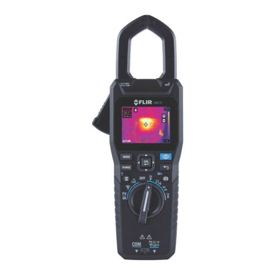
Product Description 4.1 Meter Front Clamp Jaws Clamp opening trigger MODE button (alternate functions) RANGE button (switch to manual range) Data Hold (short press) and Worklight (long press) button Function switch Probe input (negative, common) black Probe input (positive) red Image (short press) and Video (long press) capture 10. -
Page 16: Meter Back
Product Description 4.2 Meter Back Worklight Thermal imaging lens Temperature detection lens Laser pointer lens Rear compartment lock Rear compartment cover USB-C connector in compartment Figure 4.2 Back of meter. #NAS100167; r. AA/95680/95684; en-US... -
Page 17: Meter Bottom
Product Description 4.3 Meter Bottom Common negative (-) test lead connector Positive (+) test lead connector Keyed part of the COM test lead connector Figure 4.3 Back of meter. 4.4 Function Switch Positions Photo-voltaic DC Voltage, Current, and Power measurements (Section 8.17). -
Page 18: Mode Button Operation
Product Description OK button with navigation arrows, used to confirm/change settings and to navigate menus. Press to exit a displayed menu item. Short press to enter and exit the data hold mode. Long press to switch the worklight on and off. Short press to capture an image. -
Page 19: Measurement Display Icons
Product Description Worklight Bluetooth Auto Power Off (APO) 4.8 Measurement Display Icons Maximum, Minimum, Average Bar graph (right arrow ap- readings ( L to R) pears in overload) ℉ ℉ ℃ ℃ Temperature units (kilo- prefix) AC current or voltage –3 (milli- prefix) DC current or voltage... -
Page 20: Meter Power
Figure 5.1 Low battery alert screen. CAUTION The battery is not user-serviceable, contact FLIR Service if the battery requires replace- ment or service. 5.1 Powering the Meter Set the function switch to any position to power the meter, the display will switch on. -
Page 21: Worklight Apo
Meter Power 5.2.2 Worklight APO The worklight switches off after a programmable period of inactivity, to cus- tomize this setting please see Section 6.6. The default time-out is 15 minutes. The time can be set to 5, 15, or 30 minutes (select OFF to disable the work- light APO). -
Page 22: Configuring The Meter
Configuring the Meter 6.1 Navigating the Menus Press OK to access the main menu, shown below. Figure 6.1 Main Menu icons (L to R: Image Mode, Thermal Settings, Gallery, Advanced Menu, Settings) • Use the left/right navigation buttons to highlight an icon. From left to right the icons are Image Mode, Thermal Settings, Gallery, Advanced Menu, and Settings. -
Page 23: Thermal Msx Activation
Configuring the Meter 6.2.2 Thermal MSX Activation MSX provides detail and clarity to thermal images by superimposing digital camera images. Scroll to the Thermal MSX icon in the Image Mode menu, and press OK to select it. Use the Alignment tool, explained above, to align the two images. -
Page 24: Measurement Mode
Configuring the Meter 6.3.2 Measurement Mode Press OK on the Measurement Mode icon , scroll to desired mode, and press OK to select it. The measurement modes are Centre Spot, Hot Spot, Cold Spot, and No Measurements, explained the sections, below. 6.3.2.1 Centre Spot Select to measure surface temperature using cross hair targeting. -
Page 25: Laser Pointer
Configuring the Meter Figure 6.3 Figure on left is ‘auto-scaled’ while the figure on right is ‘scale locked’ 6.3.3.1 Automatic Temperature Scale Select Auto to allow the camera to use the entire thermal range. In Fig. 6.3, above, the image on the left shows the Auto mode where the temperature range uses all the available spectrum. -
Page 26: Gallery Menu
1. Download and open the METERLiNK mobile app from the App Store® (iOS® devices) or Google Play™ (Android™). 2. In the CM276 Devices menu, switch the Bluetooth utility ON (Main Menu > Settings > Device Settings). 3. Press OK on the Gallery icon in the main menu and select either Images/ Video or Data Logs. -
Page 27: Downloading Images, Videos, And Data Logs To A Pc
Configuring the Meter 4. Press OK on an image, video, or data log file to select it. 5. With an image, video, or data log open, press OK to show the option icons on the bottom of the display. 6. Scroll to the Transmit icon and press OK to share files with the ME- TERLiNK app on your mobile device. -
Page 28: Inrush Current
Configuring the Meter 6.5.3 Inrush Current The meter can capture inrush current using a 100 ms sampling window. Press OK at the inrush current icon to enable the mode. See Section 8.8 for ad- ditional information. 6.5.4 DC Current Zero The DC A Zero function allows you to null the display before taking measure- ments in the DC A mode. -
Page 29: Save Options Menu
Configuring the Meter For additional information on emissivity, see Section 6.3.5, Emissivity, and Section 15.1 (Emissivity Values for Common Materials). 6.6.2.2 Reflected Temperature Setting Reflected temperature (also known as background temperature) is thermal ra- diation originating from other objects that reflect off the target you are measur- ing. - Page 30 Configuring the Meter 6.6.4.1 Diode Mode (Classic or Smart) Press OK at the Diode sub-menu, scroll to the desired option, and press OK to select it. See the diode measurement instructions in Sections 8.15 and 8.16 for complete instructions. 6.6.4.2 Language Press OK at the Language sub-menu (Settings >...
-
Page 31: Information Menu
Configuring the Meter 6.6.4.6 Bluetooth ON/OFF 1. To toggle Bluetooth ON or OFF, press OK at the Bluetooth sub-menu (Set- tings > Device Settings > Bluetooth). 2. Press OK to confirm the selection. See Section 11 for additional informa- tion on the METERLiNK mobile app that uses Bluetooth to share images, video, and data log records. - Page 32 Configuring the Meter 6.6.5.2 Reset Options Menu Under Reset Options you can reset the meter to its factory default state or for- mat its internal memory, as explained in the next sections. Scroll to the de- sired option, use the arrow buttons to select an option, and press OK to confirm.
-
Page 33: Thermal Imaging
Thermal Imaging 7.1 Basics Thermal images represent infrared energy emitted by surfaces that you target. color variations in the image represent temperature variations. The laser pointer and display cross hairs assist in targeting. The meter also digitally displays the measured temperature of a targeted spot, in the upper left hand corner of the display, superimposed on the thermal image. -
Page 34: Configuring The Thermal Imager
Thermal Imaging In the thermal imaging mode, the meter continues to operate normally as a clamp meter and multimeter. Electrical measurements are shown underneath the temperature reading. In the Image Mode menu (Section 6.2) you can re- move the electrical measurement displays from the thermal images. The thermal imager’s field of view (FOV) is 44°... - Page 35 Thermal Imaging In multimeter mode (when not using cameras), you can capture screen shots as images (not video) by pressing the image capture button. See the Gallery menu (Section 6.4) for information on sharing and download- ing stored media. Section 11 (METERLiNK), and Section 12, PC Interface, al- so provide useful information on sharing and downloading media, but the Gallery menu is a good place to start.
-
Page 36: Clamp And Multimeter Operation
ON, recharge the batteries. See Section 13, Maintenance, for battery charg- ing details. 8.2 Auto Power OFF (APO) The CM276 has an APO function for both the device (meter) and the worklight, as explained below. 8.2.1 Device APO The meter enters sleep mode after a programmable period of inactivity, cus- tomize this in the Device settings menu, Section 6.6.4. -
Page 37: Worklight Apo
Clamp and Multimeter Operation 8.2.2 Worklight APO The worklight switches off after a programmable period of inactivity, customize this in the Device settings menu, Section 6.6.4. The default time-out is 15 mi- nutes. The time can be set to 5, 15, or 30 minutes (select OFF to disable the worklight APO). -
Page 38: Ac/Dc Current And Frequency Measurements (Clamp)
Clamp and Multimeter Operation 8.6 AC/DC Current and Frequency Measurements (Clamp) WARNING Do not measure current on a circuit if the voltage increases to more than 1000 V. This can cause damage to the instrument and can cause injury to persons. WARNING Do not use the meter to measure current above the rated frequency. - Page 39 Clamp and Multimeter Operation 9. The DC A Zero icon is shown on the display when enabled (see Section 6.5.4). 10. The Inrush current icon is shown on the display, when enabled (see Sections 6.5.3 and 8.8). Figure 8.2 Current Clamp Measurements. The upper display shows a DC measurement ex- ample (with the DC A Zero icon, see Section 6.5.4).
-
Page 40: Current Measurements Using An External Clamp Adaptor
CM276 (positive lead first). As an example, with both the CM276 and the external clamp set to the 10 mV per amp range, the CM276 will display 5 A when the external clamp is meas- uring 5 A. - Page 41 Clamp and Multimeter Operation Figure 8.3 External Clamp Adaptor Test Setup. #NAS100167; r. AA/95680/95684; en-US...
-
Page 42: Inrush Current Measurements
Clamp and Multimeter Operation 8.8 Inrush Current Measurements Set up a current test as described in the sections above, and continue with the information below. The meter can capture inrush current using a 100 ms sampling window. Press OK at the inrush current icon to enable the mode. -
Page 43: Ac/Dc Voltage And Frequency Measurements
Clamp and Multimeter Operation 8.9 AC/DC Voltage and Frequency Measurements CAUTION Use caution when the measured voltage is greater than 30 V DC or AC RMS. Refer to Figure 8.5, below, for the numbered items in this section. 1. Insert the black test lead into the negative (COM) terminal and the red test lead into the positive terminal. - Page 44 Clamp and Multimeter Operation Figure 8.5 AC and DC Voltage Measurement Setup. #NAS100167; r. AA/95680/95684; en-US...
-
Page 45: Low Impedance (Lo Z) Voltage Measurements
Clamp and Multimeter Operation 8.10 Low Impedance (Lo Z) Voltage Measurements CAUTION Use caution when the measured voltage is greater than 30 V DC or AC RMS. Lo Z Voltage measurements eliminate the affects of ‘ghost’ voltages. The pro- cedure for taking Lo Z Voltage measurements is virtually the same as for tak- ing standard Voltage measurements, the only difference is that for Lo Z Voltage measurements you select the Lo Z rotary switch position. -
Page 46: Low Pass Filter (Vfd) Voltage Measurements
Clamp and Multimeter Operation 8.11 Low Pass Filter (VFD) Voltage Measurements CAUTION Use caution when the measured voltage is greater than 30 V DC or AC RMS. The VFD feature eliminates high frequency noise in AC voltage measure- ments by means of a low pass filter. The VFD mode is designed for variable frequency drive measurements. -
Page 47: Resistance Measurements
Clamp and Multimeter Operation 8.12 Resistance Measurements WARNING Do not take resistance measurements before removing power to the resistor or circuit under test. Injury to persons can occur. Refer to Figure 8.8, below, for the numbered items in this section. 1. - Page 48 Clamp and Multimeter Operation Figure 8.8 Resistance Measurements. #NAS100167; r. AA/95680/95684; en-US...
-
Page 49: Continuity Measurements
Clamp and Multimeter Operation 8.13 Continuity Measurements WARNING Do not perform continuity tests before removing power to the device under test. Injury to persons can occur. Refer to Figure 8.9, below, for the numbered items in this section. 1. Insert the black test lead into the negative (COM) terminal and the red test lead into the positive terminal. - Page 50 Clamp and Multimeter Operation Figure 8.9 Continuity Measurements. #NAS100167; r. AA/95680/95684; en-US...
-
Page 51: Capacitance Measurements
Clamp and Multimeter Operation 8.14 Capacitance Measurements CAUTION Discharge capacitors before taking measurements. Refer to Figure 8.10, below, for the numbered items in this section. 1. Insert the black test lead into the negative (COM) terminal and the red test lead into the positive terminal. - Page 52 Clamp and Multimeter Operation Figure 8.10 Capacitance measurements. #NAS100167; r. AA/95680/95684; en-US...
-
Page 53: Classic Diode Measurements
Clamp and Multimeter Operation 8.15 Classic Diode Measurements WARNING Do not perform diode tests before removing power to the diode under test. Injury to per- sons can occur. Refer to Figure 8.11, below, for the numbered items in this section. 1. - Page 54 Clamp and Multimeter Operation Figure 8.11 Classic diode test. #NAS100167; r. AA/95680/95684; en-US...
-
Page 55: Smart Diode Test
Clamp and Multimeter Operation 8.16 Smart Diode Test WARNING Do not perform diode tests before removing power to the diode under test. Injury to per- sons can occur. In the Smart diode test mode, the meter applies an alternating test signal to the diode under test, allowing you to check the diode without having to re- verse polarity by physically moving the test leads. -
Page 56: Photovoltaic Power Measurements
The TA85 photovoltaic test leads and TA86 MC4 photovoltaic plugs have a maximum input limit of 1.5 kV DC (CAT III 1500 V DC safety rating). Use the TA85 or TA86 with the CM276 function switch set to the PV/VA position only. Use standard test leads when setting the function switch to any other position. - Page 57 Clamp and Multimeter Operation Figure 8.13 Photovoltaic Power Measurement Setup. Refer to the previous paragraph for the numbered references in this figure. #NAS100167; r. AA/95680/95684; en-US...
-
Page 58: Photovoltaic Display Example
Clamp and Multimeter Operation 8.17.1 Photovoltaic Display Example Voltage or current reading (select with MODE button). Bar graph representation of the reading. Unit of measure (DC current or voltage, select with MODE button). Auto Range icon (manual range is not available in this mode). -
Page 59: Data Logger Operation
Data Logger Operation The CM276 can automatically log up to 40,000 readings in each of 10 sets. The data logger is operational in the thermal imaging mode and in the multi- meter mode of operation. However, only electrical measurements are logged. -
Page 60: Maximum, Minimum, And Average Readings
Maximum, Minimum, and Average Readings The CM276 monitors the highest, lowest, and average electrical readings. To view these readings, follow the steps below. This feature was covered in some detail in Section 6.5.2, and in the sub-subsections referenced in the steps below. -
Page 61: Meterlink Mobile App
Images, video, and data log records can be shared with mobile devices (wire- lessly, with Bluetooth), using the FLIR METERLiNK® application. Download the METERLiNK user manual from the FLIR support site. Download the app from the App Store® (iOS® devices) or Google Play™ (Android™ devices). -
Page 62: Pc Interface
PC Interface The CM276 is compatible with Windows® PCs, allowing you to download im- ages, videos, and data log records. You can also upgrade the meter’s firm- ware by loading a firmware update file (obtained from the FLIR support site) to the meter, as explained in Section 13.3. -
Page 63: Maintenance
The meter will run for approximately 12 hours in IGM mode with the screen brightness set to medium, and for 16 hours in Multimeter mode with the screen brightness set to medium. 13.3 Upgrading the CM276 Firmware 13.3.1 General If you are not confident that you can complete the upgrade successfully, please contact our customer support site: #NAS100167;... -
Page 64: Prerequisites
Maintenance https://support.flir.com 13.3.2 Prerequisites To upgrade the firmware, you will need: • CM276 meter. • Windows PC and USB cable. • Firmware upgrade file obtained from the support site, as explained below. 13.3.3 Obtaining the Firmware Upgrade File 1. Go to the support site: https://support.flir.com... -
Page 65: Firmware Upgrade Procedure
Maintenance 5. For Figure 13.3, below, 1. Type CM276 in the search field; 2. Select FLIR / Extech Meters Software from the pull-down menu; 3. Select FLIR Soft- ware from the pull-down menu; 4. Click SEARCH; 5. Click the upgrade file to download it to your PC. -
Page 66: Disposal Of Electronic Waste
8. Select ‘YES’ when prompted by the meter to upgrade the firmware. CAUTION Do NOT switch OFF the CM276 while it is upgrading. If the meter is switched off during the upgrade process, it may not be recoverable and would have to be returned to FLIR for service. -
Page 67: Specifications
Specifications 14.1 General Specifications Display type Digital 6000 count TFT 2.4 in. (6.1 cm) color display with bar graph AC measurement type True RMS Measurement rate 3 times per second Over-range indication OL is displayed (bar graph shows arrow symbol to right of bar) Worklights Two (2) high power LED lamps... -
Page 68: Meter Power
Device: 2, 5, or 10 minutes (or OFF) Worklight: 5, 15, 30 minutes (or OFF) 14.3 Thermal Imaging Detector type FLIR Lepton microbolometer Focal Plane Array (FPA) Image modes Thermal MSX (Multi-Spectral Dynamic Imaging) Thermal Camera (IR) only Digital Camera (visible light) only... -
Page 69: Visual Imaging (Digital Camera)
Specifications IR temperature resolution 0.1℉ (0.1℃) IR temperature accuracy 5.4℉ (±3℃) or ± 3% of reading; whichever is greater Temperature scanning Continuous Emissivity 4 presets plus a custom setting (0.10 to 1.00). Default setting is 0.95 Targeting Cross hairs and Laser pointer targeting Laser pointer Class A (industrial and commercial use) Laser pointer power... -
Page 70: Wireless Connectivity
Specifications 14.7 Wireless Connectivity Wireless technology Bluetooth BLE Communications protocol METERLiNK mobile application Bluetooth range 32 ft. (10 m) 14.8 Electrical Specifications Accuracy is ± (% reading + number of digits (dgt)) at 73.4℉ ±9℉ (23℃ ±5℃), <80% RH. 14.8.1 Voltage Measurements (True RMS) Function Range Accuracy (of reading) -
Page 71: Current Measurements (True Rms)
Specifications Notes LCD Displays ‘0’ counts when the AC reading is <10 counts Overload protection: 1000 V (RMS) Input impedance: 10 MΩ //, <100 pF Lo Z input impedance: 2.5kΩ AC conversion type: AC coupled, true RMS responding, calibrated to the RMS value of a sine wave input. -
Page 72: Clamp Adaptor Input
Specifications Notes LCD Displays ‘0’ counts when the AC reading is <10 counts Overload protection: 600 A (RMS) Position error: 1% of reading AC conversion type: AC coupled, true RMS responding, calibrated to the RMS value of a sine wave input. Accuracies are given for sine waves at full scale and non-sine waves below half scale. -
Page 73: Resistance And Continuity
Specifications 14.8.5 Resistance and Continuity Function Range Accuracy (of reading) Resistance 600.0 Ω ± (1.0% + 5 dgt) 6.000 KΩ 60.00 KΩ Continuity < 30 Ω beeper ON >150 Ω beeper OFF Notes Overload protection: 1000 V RMS Maximum open circuit voltage for resistance: 1.8 V Continuity indicator: 2.7 kHz tone buzzer Continuity response time: <100 ms 14.8.6 Capacitance... - Page 74 Specifications Laser standards IEC 60825-1:2014, EN 60825-1:2014+A11:2021; CDRH Energy CEC; DOE; NRCan standards #NAS100167; r. AA/95680/95684; en-US...
-
Page 75: Appendices
Appendices 15.1 Emissivity Values for Common Materials Table 15.1 Approximate Emissivity values for common materials (for reference only). Material Emissivity Material Emissivity Asphalt 0.90 to 0.98 0.98 Cloth (black) Concrete 0.94 Skin (human) 0.98 Cement 0.96 Leather 0.75 to 0.80 0.90 0.96 Sand... - Page 76 There are no colors or “shades” of gray in infrared, only varying intensities of radiated energy. The infrared imager converts this energy into an image that we can interpret. The FLIR Infrared Training Centre offers training (including online training) and certification in all aspects of thermography: http://www.infraredtraining.com.
-
Page 77: Customer Support
CUSTOMER SUPPORT Customer support and documentation downloads are available at the link below. https://support.flir.com #NAS100167; r. AA/95680/95684; en-US... -
Page 78: Warranty
Warranty This device is protected by the FLIR Limited 10–Year Warranty. Read the war- ranty document at the link below. https://flir.com/testwarranty #NAS100167; r. AA/95680/95684; en-US... - Page 80 Customer support http://support.flir.com Copyright © 2024, FLIR Systems, Inc. All rights reserved worldwide. Disclaimer Specifications subject to change without further notice. Models and accessories subject to regional market considerations. License procedures may apply. Products described herein may be subject to US Export Regulations.
Need help?
Do you have a question about the CM276 and is the answer not in the manual?
Questions and answers