Table of Contents
Advertisement
Advertisement
Table of Contents

Related Manuals for FLIR CM275


Summary of Contents for FLIR CM275
- Page 1 USER MANUAL FLIR MODEL CM275 Imaging Clamp Meter with IGM and Bluetooth®...
-
Page 2: Table Of Contents
7. GENERAL SETTINGS 7.1 General Settings Navigation 7.1.1 Diode SMART/CLASSIC 7.1.2 APO (Auto Power OFF) 7.1.3 Datalogger Sample Rate 7.1.4 Real-time Clock 7.1.5 Battery Selection 7.1.6 Bluetooth® ON/OFF 7.1.7 Button-press tone ON/OFF 7.1.8 Language selection FLIR CM275 USER MANUAL Document Identifier: CM275-en-US_AA... - Page 3 9.15 Smart Diode Test 9.16 Capacitance Measurements 10. BLUETOOTH® COMMUNICATION 11. APPENDICES 11.1 Emissivity Factors for Common Materials 11.2 Non-Uniformity Correction 11.3 Infrared Energy and Thermal Imaging Overview 12. MAINTENANCE 12.1 Cleaning and Storage FLIR CM275 USER MANUAL Document Identifier: CM275-en-US_AA...
- Page 4 12.2 Battery Replacement 12.3 Disposal of Electronic Waste 13. SPECIFICATIONS 13.1 General specifications 13.2 Thermal Imaging Specifications 13.3 Electrical Specifications 14. TECHNICAL SUPPORT 15. WARRANTY FLIR CM275 USER MANUAL Document Identifier: CM275-en-US_AA...
-
Page 5: Advisories
1. Advisories 1.1 Copyright © 2017, FLIR Systems, Inc. All rights reserved worldwide. No parts of the software including source code may be reproduced, transmitted, transcribed or translated into any language or computer language in any form or by any means, electronic, magnetic, optical, manual or otherwise, without the prior written permission of FLIR Systems. -
Page 6: Safety
Before operating the device, you must read, understand, and follow all instructions, dangers, warnings, cautions, and notes. FLIR Systems reserves the right to discontinue models, parts or accessories, and other items, or to change specifications at any time without prior notice. ... - Page 7 This symbol, adjacent to a terminal, indicates that, under normal use, hazardous voltages may be present. Double insulation. UL listing is not an indication or a verification of the accuracy of the meter FLIR CM275 USER MANUAL Document Identifier: CM275-en-US_AA...
-
Page 8: Introduction
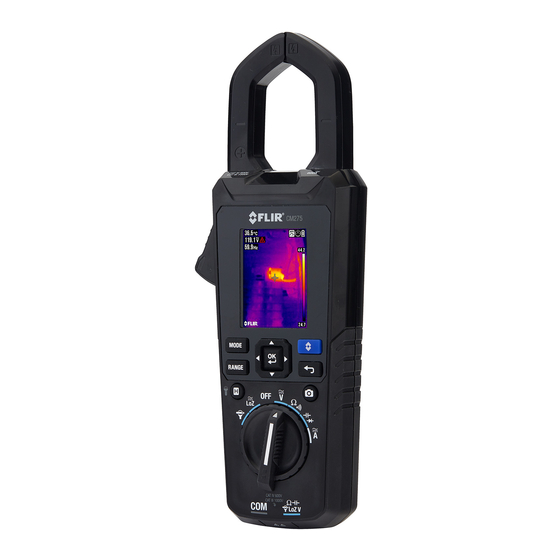
Thank you for selecting the FLIR CM275 Imaging Clamp meter with IGM (Infrared Guided Measurement) and Bluetooth®. The CM275 is a True RMS 600A AC/DC clamp meter with a radiometric Lepton Thermal Imaging system, integrated VFD Mode, Inrush Current capture, a Lo Z mode for eliminating ‘ghost’ voltages, Bluetooth®... -
Page 9: Meter Description
Image Save button (short press) Return/Exit button button (short press) Color TFT Display Clamp jaw Work lights Laser pointer lens Thermal Imaging lens Tripod mount Battery compartment (micro USB port) Battery compartment lock/unlock Fig. 4-2 Rear View FLIR CM275 USER MANUAL Document Identifier: CM275-en-US_AA... -
Page 10: Function Switch Positions
4.2 Function Switch Positions Select this position when connecting a FLIR Flex Clamp Adaptor. See Section 9.9, Clamp Adaptor (FLEX) Current and Frequency Measurements Select this position to measure in the low impedance mode. See Section 9.11, Voltage, Lo Z, and Frequency Measurements Switch the meter OFF (full power saving mode). -
Page 11: Mode Button Sequence Of Operations
L to R, row 2: Inrush current, DCA Zero, Flex Clamp icon and range, VFD, and Low Impedance mode Note that Diode and Continuity symbols also appear in the Status bar area of the display. FLIR CM275 USER MANUAL Document Identifier: CM275-en-US_AA... -
Page 12: Other Display Icons
Resistance Diode Voltage Current (Amperes) Farad (for Capacitance) Hertz (Frequency) (kilo) (milli) (micro) Out of Range warning Bar Graph Bar Graph overload indicator Meter is measuring voltage > 30 V (AC or DC) FLIR CM275 USER MANUAL Document Identifier: CM275-en-US_AA... -
Page 13: Meter Power
The user must enter the battery type (Lithium or Alkaline) in the General Settings menu before use. This allows the meter to display battery status as accurately as possible. Refer to Section 7.1.5, Battery Selection. FLIR CM275 USER MANUAL Document Identifier: CM275-en-US_AA... -
Page 14: Menu System
Color Palette, Emissivity, Temperature units, Laser pointer ON/OFF, and Cross hairs ON/OFF. Refer to Section 8.3, Thermal Settings Menu (Color Palette, Emissivity, Temperature Units, Laser Pointer, and Crosshairs) for detailed information. Fig. 6-2 Thermal Settings Menu FLIR CM275 USER MANUAL Document Identifier: CM275-en-US_AA... -
Page 15: Gallery Mode
6.2.5 General Settings Menu Press OK to open the main menu. Press OK at the General Settings icon to access the options. See next section for detailed information on the General Settings mode FLIR CM275 USER MANUAL Document Identifier: CM275-en-US_AA... -
Page 16: General Settings
7.1.4 Real-time Clock Press OK to open the date/time setting screen. Use the arrow buttons to scroll through the date and time fields and to select the current date and time. Press OK to confirm FLIR CM275 USER MANUAL Document Identifier: CM275-en-US_AA... -
Page 17: Battery Selection
Press OK to delete all saved images. The meter will ask for confirmation 7.1.11 View HELP Screen Press OK to view FLIR support contact information 7.1.12 Viewing meter component information Press OK to view meter component firmware version information and Laser data: Meter firmware version Lepton®... -
Page 18: Thermal Imaging
9. Highest reading measured in the current frame. Note: Use the Thermal Settings Menu to change the emissivity; refer to Section 8.3, Thermal Settings Menu. See also Section 11.1, Emissivity Factors for Common Materials. FLIR CM275 USER MANUAL Document Identifier: CM275-en-US_AA... -
Page 19: Thermal Imager Operation
(at a distance of 30”, the meter ‘sees’ a target spot of 1”). See Fig. 8-2. 7. The thermal imager’s FOV (Field of View) is 50 degrees (side view) and 38.6 degrees (top view) see Fig. 8-3 (a) and (b). Fig. 8-2 Distance-to-Spot ratio 30:1 FLIR CM275 USER MANUAL Document Identifier: CM275-en-US_AA... -
Page 20: Thermal Settings Menu (Color Palette, Emissivity, Temperature Units, Laser Pointer, Crosshairs)
Press OK to toggle the temperature units ( Laser pointer Press OK to toggle the laser pointer ON (blue circle) or OFF Cross hairs Press OK to switch the cross hairs ON or OFF FLIR CM275 USER MANUAL Document Identifier: CM275-en-US_AA... -
Page 21: Image Mode Menu
IR temperature measurement instead of dashes) before radiometric data can be captured. To view radiometric data within captured thermal images, copy the images to a PC and view using FLIR Tools. To view stored images: 1. Press OK to open the Main Menu 2. -
Page 22: Clamp Meter Operation
4. The blue dot next to the icon and the VFD display icon will appear 5. De-select the VFD mode by pressing OK again. The blue dot and VFD display icon will switch OFF when de-selected FLIR CM275 USER MANUAL Document Identifier: CM275-en-US_AA... -
Page 23: Max-Min Mode
3. Use the up arrow to move the cursor up to the log area of the display (the lower area is for saved images). Scroll left/right to a data ‘set’ and press OK to open it. The list of recorded measurements for the set will appear. FLIR CM275 USER MANUAL Document Identifier: CM275-en-US_AA... - Page 24 Note that a micro USB port is located in the battery compartment. When connected to a PC the CM275 operates in the same manner as an external storage medium where you can drag and drop data logs and images from the meter’s internal memory to a PC.
-
Page 25: Current And Frequency Measurements
To see the Frequency measurement for an AC Current measurement use the button to step to the Hz display. For VFD mode operation refer to Section 9.4, VFD Mode. For MAX-MIN operation, refer to Section 9.5, MAX-MIN Mode. FLIR CM275 USER MANUAL Document Identifier: CM275-en-US_AA... -
Page 26: Clamp Adaptor (Flex) Current And Frequency Measurements
2. Connect a Clamp adaptor as shown in Fig. 9-2. 3. Set the Range of the Flex Clamp Adaptor to match the range of the CM275. 4. Use the button to select the range of the CM275 (1, 10, 100 mV/A). The selected range appears on the CM275 display. -
Page 27: Inrush Current Measurements
6. Turn on the power to the circuit under test 7. When it reaches the threshold, the meter will display the RMS reading for the 100ms integration time. Fig. 9-3 Inrush Current FLIR CM275 USER MANUAL Document Identifier: CM275-en-US_AA... -
Page 28: Voltage, Lo Z, And Frequency Measurements
To view the frequency (Hz) of the measured voltage, short press the button until the Hz reading appears. For VFD mode operation refer to Section 9.4, VFD Mode. For MAX-MIN operation, refer to Section 9.5, MAX-MIN Mode. Fig. 9-4 Voltage and Frequency Measurements FLIR CM275 USER MANUAL Document Identifier: CM275-en-US_AA... -
Page 29: Resistance Measurements
Injury to persons can occur. 1. Refer to Fig. 9-5. Set the function switch to the position. 2. Use the button to select continuity. The indicator will appear. FLIR CM275 USER MANUAL Document Identifier: CM275-en-US_AA... -
Page 30: Classic Diode Test
5. If the reading is between 0.400 and 0.800V in one direction and OL (overload) in the opposite direction, the component is good. If the measurement is 0V in both directions (shorted) or OL in both directions (open), the component is bad. Fig. 9-6 Classic Diode Test FLIR CM275 USER MANUAL Document Identifier: CM275-en-US_AA... -
Page 31: Smart Diode Test
The meter display will show ± 0.400 ~ 0.800V for a good diode, ‘BAD’ for a shorted diode, and ‘O.L’ for an opened diode. See Fig. 9-7 below: Fig. 9-7 SMART Diode Test FLIR CM275 USER MANUAL Document Identifier: CM275-en-US_AA... -
Page 32: Capacitance Measurements
6. For MAX-MIN operation, refer to Section 9.5, MAX-MIN Mode. Note: For very large capacitance values, it may take several minutes for the measurement to settle and the final reading to stabilize. Fig. 9-8 Capacitance Measurements FLIR CM275 USER MANUAL Document Identifier: CM275-en-US_AA... -
Page 33: Bluetooth® Communication
10. Bluetooth® Communication When connected to a remote device running the FLIR Tools software suite, the CM275 (using the METERLiNK® protocol) can: Send readings for live display on the remote device Send saved data log files to the remote device ... -
Page 34: Appendices
±2 C temperature change. 1. Definition from the imminent international adoption of DIN 54190-3 (Non-destructive testing – Thermographic testing – Part 3: Terms and definitions). FLIR CM275 USER MANUAL Document Identifier: CM275-en-US_AA... -
Page 35: Infrared Energy And Thermal Imaging Overview
All other items are represented as a gray scale value between white and black. The CM275 also offers color images to simulate hot (lighter colors) and cold (darker colors) temperatures. -
Page 36: Maintenance
As with most electronic products, this equipment must be disposed of in an environmentally friendly way, and in accordance with existing regulations for electronic waste. Please contact your FLIR Systems representative for more details. FLIR CM275 USER MANUAL Document Identifier: CM275-en-US_AA... -
Page 37: Specifications
Approximate battery life for thermal imager: ● 2.5 hours: Alkaline ‘AA’ Battery x 3 ● 12 hours: Energizer L91 Lithium (Li/FeS ) ‘AA’ Battery x 3 ● 12 hours: Optional Rechargeable Battery: Li-Polymer; FLIR PN: TA04-KIT Calibration: 1-year calibration cycle Operating temperature: 32 to 86°F (0 to 30°C) (≤... -
Page 38: Thermal Imaging Specifications
±5.4°F (3°C) or ± 3% of reading; whichever is greater Distance to Spot (D:S) ratio 30:1 Temperature Scanning Continuous Emissivity 4 presets plus a custom setting (0.10 to 0.99) Targeting Displayed Cross hairs pinpoint center of measurement spot FLIR CM275 USER MANUAL Document Identifier: CM275-en-US_AA... -
Page 39: Electrical Specifications
For a crest factor of 1.0–2.0, add 3.0% to the accuracy. For a crest factor of 2.0–2.5, add 5.0% to the accuracy. For a crest factor of 2.5–3.0, add 7.0% to the accuracy. FLIR CM275 USER MANUAL Document Identifier: CM275-en-US_AA... - Page 40 > 60V (rms) at 600.0V range for 10Hz ~ 1kHz > 600V (rms) at 1000V range for 10Hz ~ 1kHz Hz function at ACV rotary switch: > 6V (rms) for 10Hz ~ 10kHz > 30V (rms) for 10kHz ~ 60kHz FLIR CM275 USER MANUAL Document Identifier: CM275-en-US_AA...
- Page 41 Maximum open circuit voltage for Ω: Approx. 1.8 V. Maximum open circuit voltage for diode: Approx. 1.8 V. Continuity threshold: < 30 Ω beeper on. > 150 Ω beeper off. Continuity indicator: 2.7 kHz tone buzzer. Continuity response time: <100 ms. FLIR CM275 USER MANUAL Document Identifier: CM275-en-US_AA...
- Page 42 ±(1% + 5 dgt) 45 ~ 400Hz 3000 A LCD displays ‘0’ counts when the reading is < 10 counts Additional accuracy for the Flex function is listed in the FLIR clamp adaptor User Manuals (Models TA72_TA74). Table 13.8 Flex Clamp Adaptor Function (Frequency)
-
Page 43: Technical Support
14. Technical Support Main Website http://www.flir.com/test Technical Support Website http://support.flir.com Technical support Email TMSupport@flir.com Service/Repair Support Email Repair@flir.com Support Telephone number +1 855-499-3662 option 3 (toll-free) FLIR CM275 USER MANUAL Document Identifier: CM275-en-US_AA... -
Page 44: Warranty
Any Product that is repaired or replaced under warranty is covered under this 10-10 Limited Warranty for one hundred eighty days (180) days from the date of return shipment by FLIR or for the remaining duration of the applicable Warranty Period, whichever is longer. - Page 45 RMA instructions provided by FLIR including but not limited to adequately packaging the Product for shipment to FLIR and for all packaging and shipping costs. FLIR will pay for returning to Purchaser any Product that FLIR repairs or replaces under warranty.
- Page 46 Technical Support Website http://support.flir.com Technical Support Email TMSupport@flir.com Service and Repair Email Repair@flir.com Customer Support Telephone +1 855-499-3662 option 3 (toll free) Publication Identification No.: CM275-en-US Release Version: Release Date: October 2017 Language: en-US FLIR CM275 USER MANUAL Document Identifier: CM275-en-GB_AA...
Need help?
Do you have a question about the CM275 and is the answer not in the manual?
Questions and answers