Table of Contents
Advertisement
Quick Links
Advertisement
Table of Contents

Related Manuals for FLIR CM83


Summary of Contents for FLIR CM83
- Page 1 User’s manual FLIR CM83 600 A True RMS Power Clamp Meter...
- Page 3 User’s manual FLIR CM83 #T559825; r. AI/33557/33557; en-US...
-
Page 5: Table Of Contents
Table of contents Disclaimers............. . 1 Copyright. - Page 6 Warranties ............. .40 FLIR Global Limited Lifetime Warranty ..... .40 FLIR Test and Measurement Limited 2 Year Warranty .
-
Page 7: Disclaimers
ISO 9001 standard. cordance with existing regulations for electronic waste. FLIR Systems is committed to a policy of continuous de- Please contact your FLIR Systems representative for velopment; therefore we reserve the right to make more details. -
Page 8: Safety Information
Before operating the device, you must read, understand, and follow all instruc- tions, dangers, warnings, cautions, and notes. Note FLIR Systems reserves the right to discontinue models, parts or accesso- ries, and other items, or to change specifications at any time without prior notice. - Page 9 2 Safety information WARNING You must disconnect the test leads from the circuit that you did a test on be- fore you change the range. If you do not do this, damage to the instrument and injury to persons can occur. WARNING Do not replace the batteries before you remove the test leads.
-
Page 10: Fcc Compliance
2 Safety information WARNING Do not touch expired or damaged batteries without gloves. Injury to persons can occur. WARNING Do not cause a short-circuit of the batteries. This can cause damage to the in- strument and can cause injury to persons. WARNING Do not put the batteries into a fire. -
Page 11: Industry Canada Compliance
2 Safety information This device must accept any interference received, including interference that may cause undesired operation. This equipment has been tested and found to comply with the limits for a Class B digital device, pursuant to part 15 of the FCC Rules. These limits are designed to provide reasonable protection against harmful interference in a residential instal- lation. - Page 12 2 Safety information CAUTION Exposure to Radio Frequency Radiation. To comply with RSS 102 RF exposure compliance requirements, for mobile configurations, a separation distance of at least 20 cm must be maintained be- tween the antenna of this device and all persons. This device must not be co- located or operating in conjunction with any other antenna or transmitter.
-
Page 13: Introduction
3 Introduction Thank you for choosing a FLIR CM83 clamp meter. This device is shipped fully tested and calibrated and, with proper use, will pro- vide years of reliable service. 3.1 Key features • 10 000-count digital display. • Large-scale display. -
Page 14: Description
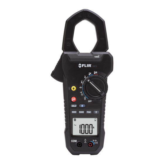
4 Description 4.1 Meter parts Figure 4.1 Front view Clamp jaw. Jaw opening trigger. Function buttons, see section 4.3 Function buttons, page 10. Navigation buttons. Non-contact voltage detector light Function switch, see section 4.2 Function switch, page 9. LCD display. Probe terminals. -
Page 15: Function Switch
4 Description Figure 4.2 Rear view Work light. Battery compartment. 4.2 Function switch The meter can measure capacitance through the probe inputs. The meter can measure resistance, continuity, or diode polarity through the probe inputs. The type of measurement is selected by the button. -
Page 16: Function Buttons
4 Description The meter can measure voltage through the probe inputs. The meter is in full power-saving mode. 4.3 Function buttons • Use the button to select Auto select or Manual select mode, see section 5.2 Auto/Manual select mode, page 14. •... -
Page 17: Display Icons And Indicators
4 Description 4.4 Display icons and indicators Figure 4.3 Display Indicates that METERLiNK® (Bluetooth) communication is ac- tive, see section 5.2 Auto/Manual select mode, page 14. Indicates that the meter is in Auto select mode. Indicates that the meter is displaying maximum reading values. Indicates that the meter is displaying minimum reading values. - Page 18 4 Description Indicates that the meter is in Phase rotation mode. Indicates that the meter is in Hold mode. Indicates the battery voltage status. Indicates that the auto power off function is enabled. Indicates that the measured voltage is greater than 30 V DC or AC RMS.
-
Page 19: Out-Of-Range Warning
4 Description 4.4.1 Out-of-range warning If the input is out-of-range, OL is displayed. #T559825; r. AI/33557/33557; en-US... -
Page 20: Operation
5 Operation NOTE Before operating the device, you must read, understand, and follow all instruc- tions, dangers, warnings, cautions, and notes. NOTE When the meter is not in use, the function switch should be set to the position. NOTE When connecting the probe leads to the device under test, connect the nega- tive lead before connecting the positive lead. -
Page 21: Auto/Manual Range Mode
5 Operation Auto select mode is the default mode of operation. When a new function is se- lected with the function switch, the starting mode is Auto select and the indi- cator is displayed. • To enter Manual select mode, press the button. -
Page 22: Voltage And Current Measurements
5 Operation Use the navigation buttons to select the Silent mode icon , see section 5.6.3.1 Selecting the mode, page 17. 5.6 Voltage and current measurements 5.6.1 Basic voltage measurements NOTE If the measured voltage is greater than 30 V DC or AC RMS, the indicator is displayed. -
Page 23: Extended Functionality
5 Operation Figure 5.1 Correct and incorrect setup Ensure that the probe leads are disconnected from the meter. Set the function switch to the position. To manually select AC, DC, or AC+DC measurement, press the button repeatedly. Refer to section 5.2 Auto/Manual select mode, page 14. To manually select the measurement range (scale), press the button repeatedly. - Page 24 5 Operation Figure 5.2 Mode icons (AC voltage measurements): Peak mode and Silent mode are enabled The navigation buttons are used to select a mode icon and to enable/disable a mode: • Use the navigation buttons to navigate to a mode icon. The cur- rently selected icon will flash.
- Page 25 5 Operation NOTE If the in-rush current under testing may be more than 100 A AC, manually set the range to 600 A before activating the in-rush current mode, see section 5.3 Auto/Manual range mode, page 15. Figure 5.3 1: Current; 2: Time; 3: Measured In-rush Current; 4: Current Detec- tion Threshold;...
- Page 26 5 Operation NOTE Do not switch to the Frequency mode until the meter is set up and actively measuring the voltage or current signal. Use the navigation buttons to select and enable Frequency mode. 5.6.3.6 Min/Max/Avg mode In Min/Max/Avg mode, the meter captures and displays the minimum or maxi- mum values and updates only when a higher/lower value is registered.
-
Page 27: Non-Contact Voltage Detector
5 Operation Press the button to switch the display between Harmonic Order Indica- tion mode and Percentage mode. Press and hold the button for 2 seconds to disable Harmonic Distortion mode. 5.6.3.8 VFD mode – Low-pass filter In VFD mode, high-frequency noise is eliminated from the voltage measurement by a low-pass filter. -
Page 28: Three-Phase Power Measurements
5 Operation Press the trigger to open the clamp jaws. Fully enclose one conductor—refer to Figure 5.1. For optimum results, center the conductor in the jaws. NOTE The + symbol on the jaw should be directed toward the power source. Connect the probe leads in parallel to the part under test. - Page 29 5 Operation Figure 5.4 Three-phase three-wire measurement Set the function switch to the position. Ensure that the meter is set to active power measurement. If the or the indicator is displayed, press the button repeatedly until none of these indicators are displayed. Take two measurements of the active power, in accordance with Figure 5.4.
- Page 30 5 Operation To return to active power measurements, press the button repeatedly until neither the nor the indicator is displayed. 5.8.2.2 Three-phase four-wire balanced/unbalanced The power of a three-phase four-wire configuration is measured in three steps, accordance with Figure 5.5. The total power is the sum of the three measure- ments: W = W Figure 5.5 Three-phase four-wire measurement #T559825;...
-
Page 31: Phase Rotation
5 Operation Set the function switch to the position. Ensure that the meter is set to active power measurement. If the or the indicator is displayed, press the button repeatedly until none of these indicators are displayed. Take three measurements of the active power, in accordance with Figure 5.5. To measure and display the power factor, press the button repeatedly until the... - Page 32 5 Operation Figure 5.6 Phase rotation Set the function switch to the position. Enter Phase rotation mode by pressing the button repeatedly until the indicator is displayed. Connect the red test lead to the presumed phase line 1 and the black test lead to the presumed phase line 3.
-
Page 33: Resistance Measurements
5 Operation One of the following results is displayed: • 123 indicates clockwise or forward rotation, which means that the pre- sumed phase line 1 is ahead of the presumed phase line 2. • 321 indicates counterclockwise or reversed rotation, which means that the presumed phase line 2 is ahead of the presumed phase line 1. -
Page 34: Continuity Test
5 Operation NOTE To protect the internal components, if a capacitor that is being tested has a charge, the meter will first discharge the cap and show diSC. After a complete discharge the meter will conduct a normal test. diSC may also be displayed if the incorrect input is provided (e.g., measuring voltage while in capacitance mode). -
Page 35: Diode Test
5 Operation 5.12 Diode test WARNING Do not do diode, resistance, or continuity tests before you remove the power from the capacitors and the other devices (when you do a test during a meas- urement). Injury to persons can occur. The meter checks diodes using an alternating test signal sent through the diode in both directions. -
Page 36: Streaming Measurement Data Using Bluetooth
5.13 Streaming measurement data using Bluetooth 5.13.1 General Some IR cameras from FLIR Systems support Bluetooth communication, and to those cameras you can stream measurement data from the meter. The data is then merged into the result table in the IR image. -
Page 37: Maintenance
As with most electronic products, this equipment must be disposed of in an envi- ronmentally friendly way, and in accordance with existing regulations for elec- tronic waste. Please contact your FLIR Systems representative for more details. #T559825; r. AI/33557/33557; en-US... -
Page 38: Technical Specifications
7 Technical specifications 7.1 General specifications Display count: 10 000 or 4000. Measuring rate: 3 times per second. Over-range indication: OL or –OL. Auto power off: Approx. 30 minutes. Low battery indicator: is displayed. Replace the battery when the indicator appears in the display. -
Page 39: Electrical Specifications
7 Technical specifications Application field Ⅰ Circuits not connected to mains Ⅱ Circuits directly connected to a low- voltage installation Ⅲ Building installation Ⅳ Source of the low-voltage installation Operating altitude: 2000 m (6562ʹ). Jaw opening: 37 mm (1.45 in.). Pollution degree: 2. - Page 40 7 Technical specifications Input impedance: 3.5 MΩ //, <100 pF. AC conversion type: AC coupled, true RMS responding, calibrated to the RMS value of a sine wave input. Accuracies are given for sine waves at full scale and non-sine waves below half scale. For non-sine waves (50/60 Hz), add the follow- ing crest factor corrections: •...
- Page 41 7 Technical specifications Table 7.3 Peak hold: peak maximum/peak minimum (AC only, Non TRMS) Function Range Accuracy 140.0 V ±(3.0% + 15 dgt) 1400 V 140.0 A ±(3.5% + 15 dgt) 850 A Overload protection: 1000 V , 600 A Peak Hold Response time: 200μs Accuracy defined for sine waves, ACV >...
- Page 42 7 Technical specifications Table 7.6 Harmonic distortion measurement Harmonic order Range Accuracy H01–H12 ±(5% + 10 dgt) 99.9% H13–H25 ±(10% + 10 dgt) Overload protection: 1000 V , 600 A • If ACV < 10 V or ACA < 10 A , rdy is displayed.
- Page 43 7 Technical specifications Table 7.8 Active power: watts (DC/AC) Function Range Accuracy 9.999 kW (10 V, 5 A ±(3% + 0.05 kW) min) 99.99 kW (10 V, 5 A ±(3% + 0.5 kW) min) 599.9 kW (10 V, 5 A ±(3% + 10 dgt) min) 9.999 kW (10 V, 5 A...
- Page 44 7 Technical specifications Table 7.10 Resistance and continuity and diode Function Range Accuracy 999.9 Ω ±(1.0% + 5 dgt) Resistance 9.999 kΩ ±(1.0% + 3 dgt) 99.99 kΩ Continuity 999.9 Ω ±(1.0% + 5 dgt) Diode 0.40–0.80 V ±0.1V Overload protection: 1000 V Maximum test current: Approx.
-
Page 45: Technical Support For External Meters
8 Technical support for external meters Website http://www.flir.com/test Technical support TMSupport@flir.com Repairs Repair@flir.com Phone number +1 855-499-3662 (toll-free) #T559825; r. AI/33557/33557; en-US... -
Page 46: Warranties
PRICE AND HAVE NO OTHER OBLIGATION OR LIABIL- “Product”) purchased either directly from FLIR Commer- ITY TO BUYER WHATSOEVER. cial Systems Inc and affiliates (FLIR) or from an author- ized FLIR distributor or reseller that Purchaser registers 5. WARRANTY EXCLUSIONS AND DISCLAIMERS. -
Page 47: Warranty
7. NON-WARRANTY RETURN. Purchaser may request including accessories which may have their own warranty. that FLIR evaluate and service or repair a Product not cov- 3. WARRANTY PERIODS. The applicable Limited War- ered under warranty, which FLIR may agree to do in its ranty Period measured from the Purchase data are: sole discretion. - Page 48 RANTY AGREEMENT BETWEEN PURCHASER AND 7. NON-WARRANTY RETURN. Purchaser may request FLIR AND SUPERSEDES ALL PRIOR WARRANTY NE- that FLIR evaluate and service or repair a Product not cov- GOTIATIONS, AGREEMENTS, PROMISES AND ered under warranty, which FLIR may agree to do in its UNDERSTANDINGS BETWEEN PURCHASER AND sole discretion.
- Page 50 A note on the technical production of this publication This publication was produced using XML — the eXtensible Markup Language. For more information about XML, please visit http://www.w3.org/XML/ A note on the typeface used in this publication This publication was typeset using Linotype Helvetica™ World. Helvetica™ was designed by Max Miedinger (1910–1980) LOEF (List Of Effective Files) T501025.xml;...
- Page 52 Customer support http://support.flir.com Copyright © 2016, FLIR Systems, Inc. All rights reserved worldwide. Disclaimer Specifications subject to change without further notice. Models and accessories subject to regional market considerations. License procedures may apply. Products described herein may be subject to US Export Regulations. Please refer to exportquestions@flir.com with any questions.
Need help?
Do you have a question about the CM83 and is the answer not in the manual?
Questions and answers