Table of Contents
Advertisement
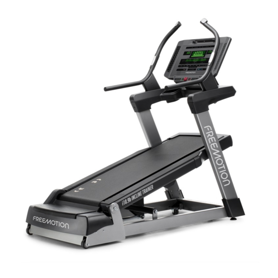
Model No. FMTK74218.2
Serial No.
USER'S MANUAL
Write the serial number in the space
above for reference.
Serial Number
Decal
QUESTIONS?
If you have questions, or if parts
are damaged or missing,
please see HOW TO CONTACT
CUSTOMER CARE on the back
cover of this manual.
CAUTION
Read all precautions and
instructions in this manual before
using this equipment. Keep this
freemotionfitness.com
manual for future reference.
Advertisement
Table of Contents

Related Manuals for Freemotion i10.9b INCLINE TRAINER


Summary of Contents for Freemotion i10.9b INCLINE TRAINER
- Page 1 Model No. FMTK74218.2 Serial No. USER’S MANUAL Write the serial number in the space above for reference. Serial Number Decal QUESTIONS? If you have questions, or if parts are damaged or missing, please see HOW TO CONTACT CUSTOMER CARE on the back cover of this manual.
-
Page 2: Table Of Contents
LIMITED WARRANTY............. . . Back Cover FREEMOTION and IFIT are registered trademarks of ICON Health & Fitness, Inc. App Store is a trademark of Apple Inc., registered in the U.S. -
Page 3: Important Precautions
FreeMotion Fitness assumes no responsibility for personal injury or prop- erty damage sustained by or through the use of this product. - Page 4 20. Keep fingers, hair, and clothing away from 25. Never insert or drop any object into any the moving walking belt. opening on the incline trainer. 21. The incline trainer is capable of high speeds. 26. Make sure to perform all maintenance proce- Adjust the speed in small increments to dures outlined in this manual.
-
Page 5: Warning Decal Placement
WARNING DECAL PLACEMENT These drawings show the location(s) of the warning decal(s). If a decal is missing or illegible, see the back cover of this manual and request a free replacement decal. Apply the decal in the location shown. Note: The decal(s) may not be shown at actual size. Note: There is one decal on each side... -
Page 6: Before You Begin
I10.9B INCLINE TRAINER. The of this manual. To help us assist you, note the product ® I10.9B INCLINE TRAINER provides an impressive model number and serial number before contacting us. selection of features designed to make your workouts The model number and the location of the serial num- more effective and enjoyable. -
Page 7: Part Identification Chart
PART IDENTIFICATION CHART Use the drawings below to identify small parts used for assembly. The number in parentheses below each draw- ing is the key number of the part, from the PART LIST near the end of this manual. The number following the key number is the quantity used for assembly. -
Page 8: Assembly
ASSEMBLY • Assembly requires two persons. • Assembly requires the following tools: • Place all parts in a cleared area and remove the one 3/8" hex key packing materials. Do not dispose of the packing materials until you fi nish all assembly steps. one 7/32"... - Page 9 2. Partially tighten four 5/16" x 3/4" Screws (51) with three 5/16" Star Washers (61) into the Left Upright (149) as shown; do not fully tighten the Screws yet. 3. With the help of a second person, slide the Right Upright (150) onto the Base Frame (56).
- Page 10 4. Partially tighten four 5/16" x 3/4" Screws (51) with three 5/16" Star Washers (61) into the Right Upright (150) as shown; do not fully tighten the Screws yet. 5. Place the handrail assembly (B) upside down on a soft surface. Remove and discard the four indicated screws (C).
- Page 11 6. With the help of a second person, set the Handrail Base (154) on the Uprights (149, 150). See the inset drawing. The 5/16" x 3/4" Cap Screws (88) must be inside the holes (D) in the bottom of the Handrail Base. Then, slide the Handrail Base forward.
- Page 12 8. Attach the Handrail Base Bottom Cover (155) with fourteen #8 x 3/4" Screws (16); start all fourteen Screws, and then tighten them. Do not overtighten the Screws. 9. Set the Right Handrail Assembly (113) on the right side of the Handrail Base (154). Attach the Right Handrail Assembly with two 5/16"...
- Page 13 10. Attach the Right Outer Cover (143) with three #8 x 3/4" Screws (16); do not overtighten the Screws. Next, attach the Right Inner Cover (145) with a 1/4" x 1" Screw (8); do not overtighten the Screw. Attach the Left Outer Cover (not shown) and the Left Inner Cover (not shown) as described above.
- Page 14 12. Attach the console assembly (F) with four 5/16" x 3/4" Screws (51) and four 5/16" Star Washers (61). Torque the Screws to 17 pound-feet (23 Newton-meters). 13. Attach the Console Back (5) to the console assembly (F) with four #8 x 3/4" Screws (16); start all four Screws, and then tighten them.
- Page 15 14. Attach the Left Upright Cover (151) to the Left Upright (149) with three #8 x 3/4" Screws (16); start all three Screws, and then tighten them. Do not overtighten the Screws. Attach the Right Upright Cover (not shown) to the Right Upright (not shown) as described above.
-
Page 16: How To Move The Incline Trainer
HOW TO MOVE THE INCLINE TRAINER Before moving the incline trainer, unplug the power cord. Note: It may be necessary to discon- nect a CATV cable and a network wire from the incline trainer, depending on how far the incline trainer will be moved. -
Page 17: How To Connect The Incline Trainer
120-volt circuit. No other appliance should be on an RF modulator to work correctly. RF modulators are not available from FreeMotion Fitness, but are avail- the same circuit. This product has a cord with an equipment-grounding conductor and a grounding plug. -
Page 18: How To Upgrade The Console
HOW TO UPGRADE THE CONSOLE Your incline trainer’s console has been preconfigured to operate with a digital TV (see the drawings below). To learn about the features of the console, see page 19. To learn about the features of the digital TV, see the user’s manual included with the digital TV. -
Page 19: How To Use The Console
HOW TO USE THE CONSOLE FEATURES OF THE CONSOLE As you exercise, the console will display instant exer- cise feedback. You can also measure your heart rate The incline trainer console offers a selection of fea- using the handgrip heart rate monitor or a compatible tures designed to make your workouts more effective heart rate monitor. - Page 20 HOW TO TURN ON THE POWER HOW TO USE THE MANUAL MODE 1. Plug in the power cord. 1. Insert the key into the console. See HOW TO CONNECT THE POWER CORD on See HOW TO TURN ON THE POWER at the left. page 17.
- Page 21 6. Follow your progress with the displays. 7. Measure your heart rate if desired. The matrix—The matrix will display a track that You can measure your heart rate using either the represents 1/4 mile (400 meters). As you exercise, handgrip heart rate monitor or a compatible heart the indicators around the track will appear in suc- rate monitor.
- Page 22 9. When you are fi nished exercising, press the Each workout is divided into several one-minute Stop button. segments. One speed setting and one incline set- ting are programmed for each segment. Note: The Step onto the foot rails, press the Stop button, and same speed and/or incline settings may be pro- adjust the incline of the incline trainer to zero.
- Page 23 HOW TO USE A SET-A-GOAL WORKOUT 6. Follow your progress with the displays. 1. Insert the key into the console. See step 6 on page 21. See HOW TO TURN ON THE POWER on page 20. 7. Measure your heart rate if desired. 2.
- Page 24 4. Enter your age if desired. IMPORTANT: The heart rate target is intended only to provide motivation. Make sure to exer- See step 3 on page 20. cise at an intensity that is comfortable for you. If the speed and incline settings are uncomfort- 5.
- Page 25 6. Begin exercising. Then, open the iFit–Smart Cardio Equipment app and follow the instructions to set up an iFit account The fitness test is divided into segments. During and customize settings. the fitness test, the profile in the display will show your progress.
- Page 26 HOW TO CONNECT YOUR HEART RATE MONITOR THE MAINTENANCE MODE TO THE CONSOLE The console features a maintenance mode that keeps The console is compatible with all Bluetooth Smart track of incline trainer information and allows you to heart rate monitors. personalize console settings.
- Page 27 TV SETUP—This display is used during setup of the THE OPTIONAL CHEST HEART RATE MONITOR optional TV. Whether your LANGUAGE—This display will show which language goal is to is selected for the text displayed on the console. burn fat or to strengthen your Note: There are several other optional screens in the cardiovascular...
-
Page 28: Preventive Maintenance
PREVENTIVE MAINTENANCE Regular maintenance is necessary for optimal perfor- 2. Unplug the power cord. Next, remove the 3/8" x mance and long life of the incline trainer. Please read 1 1/4" Screws (37), and lift off the Motor Hood (75). and follow all instructions below. - Page 29 REPLACING THE WALKING PLATFORM AND THE 2. Remove the 3/8" x 1 1/4" Screws (37) and lift off WALKING BELT the Motor Hood (75). Inspect the walking platform periodically for wear. If there is any wood showing through the phenolic coat- ing, or if the surface is damaged, the walking platform should be turned over or replaced.
- Page 30 If you are turning over or replacing the Walking 6. Lift the right or left edge of the Walking Belt (18) Platform (23), go to step 5. and look for a small arrow printed on the under- side of the Walking Belt; move the Walking Belt, If you are replacing only the Walking Belt if necessary, as you look for an arrow.
- Page 31 7. Center the Walking Belt (18), if necessary (see LUBRICATING THE WALKING BELT pages 33 and 34). Then, plug in the power cord, step onto the foot rails, insert the key into the con- Your incline trainer features a walking belt coated sole, and press the Start button.
-
Page 32: Preventive Maintenance Record
PREVENTIVE MAINTENANCE RECORD Photocopy this form and use it to record the preventive maintenance performed on the incline trainer. Each copy of the form can be used for six months (26 weeks). When maintenance is performed, write the date in the appro- priate spaces. -
Page 33: Troubleshooting
TROUBLESHOOTING MAINTENANCE SYMPTOM: The power turns off during use Regular maintenance is important for optimal per- a. Check the power switch located on the incline formance and to reduce wear. Inspect and properly trainer near the power cord (see drawing c at the tighten all parts each time the incline trainer is used. - Page 34 b. If the walking belt has shifted to the left: SYMPTOM: The walking belt stops or the incline Remove the key and unplug the power cord. cannot be adjusted even though the console Using a 7/32" hex key, turn the roller adjustment remains lit screws in the directions shown, 1/4 of a turn each.
-
Page 35: Exercise Guidelines
EXERCISE GUIDELINES Burning Fat—To burn fat effectively, you must exer- WARNING: cise at a low intensity level for a sustained period of Before beginning this time. During the first few minutes of exercise, your or any exercise program, consult your physi- body uses carbohydrate calories for energy. - Page 36 SUGGESTED STRETCHES The correct form for several basic stretches is shown at the right. Move slowly as you stretch —never bounce. 1. Toe Touch Stretch Stand with your knees bent slightly and slowly bend forward from your hips. Allow your back and shoulders to relax as you reach down toward your toes as far as possible.
-
Page 37: Part List
PART LIST Model No. FMTK74218.2 R0219A Key No. Qty. Description Key No. Qty. Description Side Cover 5/16" x 3/4" Screw #8 x 3/4" Truss Head Screw Drive Motor Center Isolator Drive Motor Isolator 3/8" Jam Nut 3/4" x 1/2" Screw Console Back Torsion Bar Bushing 1/4"... - Page 38 Key No. Qty. Description Key No. Qty. Description Filter Frame Crossbar Cap #6 x 1/2" Screw M3 x 12mm Bolt 1/2" Jam Nut 98ºC Thermal Switch #10 Nut M3 Nut Key/Clip Switch Bracket Cotter Pin Cable Tie Left Outer Cover Power Cord Right Outer Cover Incline Motor Bracket...
-
Page 39: Exploded Drawing
EXPLODED DRAWING A Model No. FMTK74218.2 R0219A... - Page 40 EXPLODED DRAWING B Model No. FMTK74218.2 R0219A...
- Page 41 EXPLODED DRAWING C Model No. FMTK74218.2 R0219A...
- Page 42 EXPLODED DRAWING D Model No. FMTK74218.2 R0219A...
- Page 43 EXPLODED DRAWING E Model No. FMTK74218.2 R0219A...
-
Page 44: How To Contact Customer Care
LIMITED WARRANTY WARRANTY PERIODS AND COVERAGE WHAT TO DO IF SERVICE IS REQUIRED FreeMotion Fitness warrants this product to be free from FreeMotion Fitness warranty service may be obtained by defects in workmanship and material under normal use and contacting the authorized dealer from which you purchased service conditions.
Need help?
Do you have a question about the i10.9b INCLINE TRAINER and is the answer not in the manual?
Questions and answers