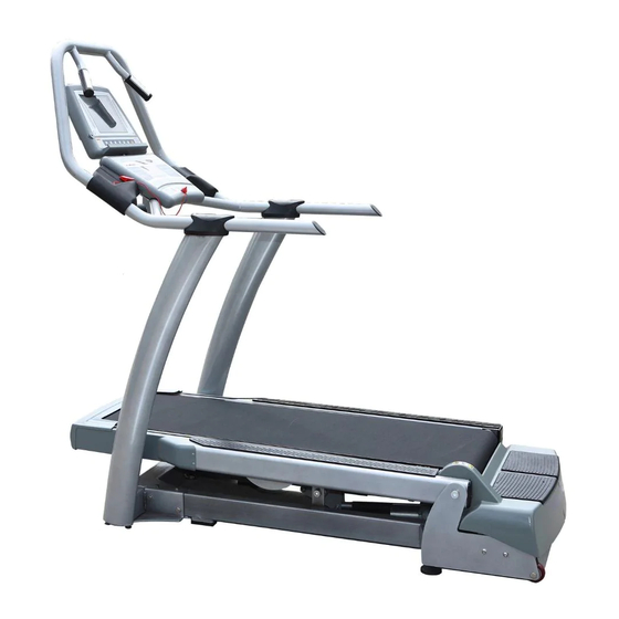
Freemotion Incline Trainer User Manual
Incline trainer
Hide thumbs
Also See for Incline Trainer:
- User manual (52 pages) ,
- User manual (42 pages) ,
- User manual (44 pages)
Advertisement
Table of Contents
- 1 Table of Contents
- 2 Warning Decal Placement
- 3 Important Precautions
- 4 Before You Begin
- 5 Assembly
- 6 How to Connect the Incline Trainer
- 7 How to Move the Incline Trainer
- 8 How to Upgrade the Console
- 9 How to Use the Basic Console
- 10 Preventive Maintenance
- 11 Six-Month Preventive Maintenance Record
- 12 Troubleshooting
- 13 Exercise Guidelines
- 14 Part List
- 15 Exploded Drawing
- 16 How to Contact Customer Care
- Download this manual
See also:
User Manual
Model No.
Serial No.
The model number and serial num-
ber are found in the location shown
below. Write the model number and
serial number in the space above.
Serial
Number
Decal
QUESTIONS?
If you have questions, or if parts
are damaged or missing, please
see HOW TO CONTACT CUS-
TOMER CARE on the back cover
of this manual.
CAUTION
Read all precautions and instruc-
tions in this manual before using
this equipment. Keep this manual
for future reference.
USERʼS MANUAL
www.freemotionfitness.com
Advertisement
Table of Contents

Related Manuals for Freemotion Incline Trainer


Summary of Contents for Freemotion Incline Trainer
- Page 1 USERʼS MANUAL Model No. Serial No. The model number and serial num- ber are found in the location shown below. Write the model number and serial number in the space above. Serial Number Decal QUESTIONS? If you have questions, or if parts are damaged or missing, please see HOW TO CONTACT CUS- TOMER CARE on the back cover...
-
Page 2: Table Of Contents
HOW TO CONNECT THE INCLINE TRAINER ........ -
Page 3: Warning Decal Placement
WARNING DECAL PLACEMENT These drawings show the locations of the warning decals. If a decal is missing or illegible, see the back cover of this manual and request a free replacement decal. Apply the decal in the location shown. Note: The de- cals may not be shown at actual size. -
Page 4: Important Precautions
To reduce the risk of serious injury, read all important precautions and in- structions in this manual and all warnings on your incline trainer before using your incline trainer. FreeMotion Fitness assumes no responsibility for personal injury or property damage sustained by or through the use of this product. - Page 5 19. Do not attempt to move the incline trainer will void the warranty and may result in dam- until it is properly assembled. (See ASSEM- age to the incline trainer. BLY on page 7, and HOW TO MOVE THE IN- 23.
-
Page 6: Before You Begin
For your benefit, read this manual carefully before you use the incline trainer. If you have questions Before reading further, please familiarize yourself with after reading this manual, please see the back cover of the parts that are labeled in the drawing below. -
Page 7: Assembly
ASSEMBLY Assembly requires two persons. Set the incline trainer in a cleared area and remove all packing materials. Do not dispose of the packing materials until assembly is completed. Assembly requires a 3/8" hex key , a 7/32" hex key , and a Phillips screwdriver Use the drawings below to identify the assembly hardware. - Page 8 Upright and into the Base Frame; do not tighten the Bolts yet. Repeat this step on the left side of the incline trainer; there are no wires on the left side. 3. Partially tighten two 1/2" x 4 1/2" Bolts (96) with two 1/2"...
- Page 9 4. Locate the Bolt (B) on the top of each Upright (93). With Console the help of a second person, set the console assembly Assembly onto the top of the Uprights. Make sure that the Bolts are inserted into the indicated holes in the bottom of the console assembly (only one side is shown).
- Page 10 #8 x 1/2" Washer Head Screws (2) and the four #8 x 3/4" Screws (16) that you removed in step 7. 9. Make sure that all parts are properly tightened before you use the incline trainer. To protect the floor or carpet, place a mat beneath the incline trainer.
-
Page 11: How To Connect The Incline Trainer
HOW TO CONNECT THE INCLINE TRAINER DANGER: HOW TO CONNECT THE POWER CORD IN THE UK Improper connection This product must be earthed. If it should malfunc- of the equipment-grounding conductor can tion or break down, earthing provides a path of least result in an increased risk of electric shock. -
Page 12: How To Move The Incline Trainer
Wheels HOW TO UPGRADE THE CONSOLE Your incline trainer has been preconfigured to operate with a basic console and with an optional personal televi- sion, which offers additional functionality. With the optional personal television, you can watch the television pro- grams of your choice, or connect and use your own VCR or DVD player. -
Page 13: How To Use The Basic Console
To purchase iFit cards, please see the front cover of the incline trainer with the touch of a button. As you of this manual or go to www.iFit.com. iFit cards are exercise, the console will display continuous exercise also available at select stores. - Page 14 Start/Stop button. stop. Test the clip by carefully taking a few steps backward; if the key is not pulled from the console, 4. Change the incline of the incline trainer as de- adjust the position of the clip. sired. IMPORTANT: If there is a sheet of clear plastic on To change the incline of the incline trainer, press the face of the console, remove the plastic.
- Page 15 Press the Display button repeatedly to se- Before using lect the desired display mode. the handgrip pulse sensor, As you walk or run on the incline trainer, the upper remove the display can show the following workout informa- sheets of clear Contacts...
- Page 16 The display can show the speed of the walking belt, 3. Press the Start/Stop button to start the workout. the incline of the incline trainer, a profile of the workout, the time remaining in the workout, the dis- A moment after you press the Start/Stop button,...
- Page 17 MANUAL CONTROL WORKOUT A moment after you press the Start/Stop button, 1. Insert the key into the console. the incline trainer will begin moving. Hold the handrails and begin walking. See HOW TO TURN ON THE POWER on page During the workout, the profile will show the incline of the walking belt.
- Page 18 The FreeMotion Fitness Test measures your fit- ness level on a scale of 1 to 10. The FreeMotion Fitness Test ends after either 28 minutes or when you Note: If you press the Start/Stop button during the reach a certain heart rate.
- Page 19 HOW TO USE A HEART RATE WORKOUT trainer will automatically adjust to the first speed and incline settings of the workout. Hold the CAUTION: handrails and begin walking. If you have heart prob- lems, or if you are over 60 years of age and The heart rate workouts are divided into several have been inactive, do not use the pulse work- one-minute segments.
- Page 20 3 on page 22. Incline buttons; however, when the next segment of the workout begins, the incline trainer will au- tomatically adjust to the speed and incline set- Press the Enter button to select the desired work- tings for the next segment.
- Page 21 1. Insert the key into the console. A moment after you press the Start/Stop button, the incline trainer will automatically adjust to the See HOW TO TURN ON THE POWER on page first speed and incline settings of the workout. Hold the handrails and begin walking.
- Page 22 The console has a maintenance mode that keeps track If desired, create a custom workout. Press the of the total number of hours that the incline trainer has Display button until the desired custom workout is been operated and the total distance that the walking shown.
-
Page 23: Preventive Maintenance
While the walking belt is moving, check the incline trainer for unusual noises or odors. If any of these problems exists, please see the back cover of this manual. Remove the key and un- plug the power cord. - Page 24 TURNING THE WALKING PLATFORM Both sides of the walking platform are designed to be used as walking surfaces. Inspect the walking platform peri- odically for wear. If there is any wood showing through the phenolic coating, or if the surface is damaged, the walking platform should be turned over.
- Page 25 REPLACING THE WALKING BELT When the walking belt becomes worn, it should be replaced. The walking belt will need to be replaced after every 10,000 to 15,000 miles (16,000 to 24,000 kilometers). See the Service Manual for replacement instructions. Please see the back cover of this manual to order a new walking belt. REPLACING THE WALKING PLATFORM When both sides of the walking platform become worn, the walking platform should be replaced.
-
Page 26: Six-Month Preventive Maintenance Record
MONTH PREVENTIVE MAINTENANCE RECORD Photocopy this form and use it to record the preventive maintenance performed on the incline trainer. Each copy of the form can be used for six months (26 weeks). When maintenance is performed, write the date in the appropriate spaces. -
Page 27: Troubleshooting
2. SYMPTOM: THE POWER TURNS OFF DURING USE a. Check the reset/off circuit breaker located on the incline trainer near the power cord. (See drawing c above.) Make sure that the reset/off circuit breaker is switched to the “reset” position. - Page 28 This indicates that a controller error may have occurred. To correct the problem, turn the power switch off, wait 5 seconds and then turn the power switch back on. During the calibration routine, the incline trainer will automatically travel to the lowest incline level and then return to level.
-
Page 29: Exercise Guidelines
EXERCISE GUIDELINES WARNING: Burning Fat—To burn fat effectively, you must exer- cise at a low intensity level for a sustained period of Before beginning any time. During the first few minutes of exercise, your exercise program, consult your physician. body uses carbohydrate calories for energy. Only after This is especially important for persons over the first few minutes of exercise does your body begin age 35 or persons with pre-existing health... -
Page 30: Part List
PART LIST R0909A To locate the parts listed below, see the EXPLODED DRAWING near the end of this manual. Key No. Qty. Description Key No. Qty. Description Side Cover Handgrip #8 x 1/2" Washer Head Screw Drive Motor Center Isolator Drive Motor Isolator 3/8"... - Page 31 Key No. Qty. Description Key No. Qty. Description Grip Left Drive Roller Guard 3/8" x 2 3/4" Bolt 72" Wire Harness Handrail 1/4" x 3/4" Bolt Handrail Endcap 1/4" U-Nut Key/Clip 35" Wire Harness 1/4" x 1/2" Screw TV Console #8 x 1/2"...
-
Page 36: How To Contact Customer Care
(see the PART LIST and the EXPLODED DRAWING near the end of this manual). Call toll-free: 1-800-201-2109, Mon.–Fri. 8 a.m.–5 p.m. MT Write: FreeMotion Fitness, 1500 S. 1000 W., Logan, UT 84321-9813 Part No. 278867 R0909A Printed in USA © 2009 ICON IP, Inc.
Need help?
Do you have a question about the Incline Trainer and is the answer not in the manual?
Questions and answers