Table of Contents
Advertisement
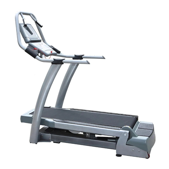
Model No. FMTK7256-INT.0
Serial No.
Write the serial number in the
space above for future reference.
Serial
Number
Decal
QUESTIONS?
If you have questions, or if parts
are damaged or missing, please
see HOW TO CONTACT CUS-
TOMER CARE on the back cover
of this manual.
CAUTION
Read all precautions and instruc-
tions in this manual before using
this equipment. Keep this manual
for future reference.
USERʼS MANUAL
www.freemotionfitness.com
Advertisement
Table of Contents

Related Manuals for Freemotion FMTK7256-INT.0


Summary of Contents for Freemotion FMTK7256-INT.0
- Page 1 USERʼS MANUAL Model No. FMTK7256-INT.0 Serial No. Write the serial number in the space above for future reference. Serial Number Decal QUESTIONS? If you have questions, or if parts are damaged or missing, please see HOW TO CONTACT CUS- TOMER CARE on the back cover of this manual.
-
Page 2: Table Of Contents
HOW TO CONTACT CUSTOMER CARE ..........Back Cover FREEMOTION is a registered trademark of ICON IP, Inc. -
Page 3: Important Precautions
To reduce the risk of serious injury, read all important precautions and in- structions in this manual and all warnings on your incline trainer before using your incline trainer. FreeMotion Fitness assumes no responsibility for personal injury or property damage sustained by or through the use of this product. - Page 4 DANGER: 18. The pulse sensor is not a medical device. Always unplug the power Various factors, including the user's move- cord before cleaning the incline trainer and ment, may affect the accuracy of heart rate before performing the maintenance and ad- readings.
-
Page 5: Warning Decal Placement
WARNING DECAL PLACEMENT These drawings show the location(s) of the warning decal(s). If a decal is missing or illegible, see the back cover of this manual and request a free replacement decal. Apply the decal in the location shown. Note: The decal(s) may not be shown at actual size. HIGH VOLTAGE Disconnect line cord from outlet before servicing. -
Page 6: Before You Begin
BEFORE YOU BEGIN Thank you for selecting the revolutionary after reading this manual, please see the back cover of FREEMOTION INCLINE TRAINER. The INCLINE this manual. To help us assist you, note the product ® TRAINER provides an impressive selection of features model number and serial number before contacting us. -
Page 7: Assembly
ASSEMBLY Assembly requires two persons. Set the incline trainer in a cleared area and remove all packing materials. Do not dispose of the packing materials until assembly is completed. Assembly can be completed using a 3/8" hex key, a 7/32" hex key, and a Phillips screwdriver. Use the drawings below to identify the assembly hardware. - Page 8 2. Locate the 80" Wire Harness (118) and 72” Wire Harness (119) in the Upright (93) access hole. Connect the 80" Wire Harness (118) and 72” Wire Harness (119) at the front of the Uprights (93). See the inset drawing. The connectors should slide together easily and snap into place.
- Page 9 5. Orient one of the Handrail Brackets (92) with the 5/16" x 1 3/4" Bolt (113) postioned as shown. Insert the 72" Wire Harness (119) through the large hole in the Handrail Bracket. Attach the Handrail Bracket (92) to the top of the right Upright (93) with two 5/16"...
-
Page 10: How To Move The Incline Trainer
8. Attach the handrail assembly to the Handrail Brackets (92) with four 3/8" x 1" Bolts (51); start all four Bolts, Handrail and then tighten each of them. Assembly 9. After the incline trainer is placed in the location where it will be used (see HOW TO MOVE THE INCLINE TRAINER on page 30), make sure that both Rear Leveling Feet (38) and the Base Pads (not shown) rest... -
Page 11: Operation And Adjustment
OPERATION AND ADJUSTMENT DANGER: WARRANTY INFORMATION Improper connection The warranty for this product does not cover damage of the equipment-grounding conductor can or equipment failure caused by electric wiring not in result in an increased risk of electric shock. compliance with electrical codes or the specifications Check with a qualified electrician or service- in this manual, or failure to provide reasonable and man if you are in doubt as to whether the... - Page 12 Note: If there is a sheet of plastic on Matrix the face of the con- sole, remove it. Display FEATURES OF THE CONSOLE to keep your heart rate near target levels during your workouts, and three unique FITNESS TEST programs The console offers an impressive array of features de- that measure your relative fitness level.
- Page 13 OVERVIEW OF THE CONSOLE The ENTER button and + and – buttons—These but- For your benefit, please read all of the instructions tons are used to enter infor- on pages 13 and 14 before you use the incline mation into the console. trainer.
- Page 14 Distance/Vertical with both hands; your palms must be resting on the Distance—This section of upper contacts, and your fingers must be touching the lower contacts. Avoid moving your hands. When the main display will show the distance that you have your pulse is detected, the PULSE indicator above the walked or run, in miles or main display will begin to flash, and then your heart...
- Page 15 GETTING STARTED HOW TO USE THE QUICK START MODE 1. Plug in the power cord. If you do not plan to use a program, the QUICK START mode will allow you to simply start exercising See HOW TO CONNECT THE POWER CORD on and adjust the speed and incline of the incline trainer page 11.
- Page 16 4. Follow your progress with the matrix and the HOW TO USE A MANUAL PROGRAM main display. The MANUAL TIME program allows you to enter a The matrix will show your progress and the incline time goal for your workout. The program will then settings that you select.
- Page 17 4. Enter your weight. As you exercise, change the speed of the walking belt as desired by pressing the SPEED + and – Next, the words ENTER WEIGHT and a weight buttons. Each time a button is pressed, the speed setting of 185 pounds will appear in the main dis- setting will change by 0.1 Km/H;...
- Page 18 GERKIN FIT TEST, the EBBEL- measure of your ability to take in and utilize oxygen to ING FIT TEST, or the FREEMOTION FIT TEST. generate energy for endurance activities such as run- ning and cycling. In technical terms, VO...
- Page 19 Either the word MALE or the word FEMALE will appear in When the FREEMOTION FITNESS TEST is com- the main display. To enter your gender, press the + pleted, the walking belt will slow to a stop and your and –...
- Page 20 HOW TO USE A HEART RATE PROGRAM 4. Enter your age. HEART RATE programs automatically control the See step 3 on page 16. speed and incline of the incline trainer to keep your 5. Enter your weight. heart rate near a target level while you exercise. Follow the steps below to use a HEART RATE pro- gram.
- Page 21 If desired, you can change the target heart rate and then the speed and/or incline of the incline setting by pressing the + and – buttons beside the trainer will change, if needed, to bring your heart ENTER button. The buttons can be held down to rate closer to the target heart rate setting for the change the target heart rate setting quickly.
- Page 22 HOW TO USE AN INTERVAL PROGRAM 5. Enter a program time. The INTERVAL programs will automatically adjust the See step 8 on page 21. incline of the walking belt as they guide you through an 6. Enter a minimum incline setting. effective interval training workout.
- Page 23 segment of the program begins, the incline Each program is divided into several time seg- trainer will automatically adjust to the incline ments of different lengths. The main display will setting for the next segment. show both the time remaining in the program and the time remaining in the current segment of the program.
- Page 24 HOW TO USE A WALK/RUN PROGRAM If you have selected the 5K or 10K program, skip to step 6. If you have selected the CROSS COUNTRY program, continue to step 5. The 5K program is designed to help you train for a 5K race.
- Page 25 HOW TO USE A TERRAIN PROGRAM 4. Enter a maximum incline setting. During the HILL program, the incline of the incline The words MAX INCLINE and the incline setting trainer will depend on the vertical distance goal and will appear in the main display. To enter a different the speed setting that you set.
- Page 26 HOW TO USE A FITNESS OR RANDOM PROGRAM 4. Enter your weight. The FITNESS program controls the speed and incline See step 4 on page 17. of the incline trainer to create a workout with a warm- If you have selected a RANDOM program, con- up period, a steady workout, and a cool-down period.
- Page 27 HOW TO USE A CUSTOM PROGRAM and incline settings of the program. Hold the handrails and begin walking. 1. Insert the key into the console. Each CUSTOM program is divided into several See GETTING STARTED on page 15. segments. One speed setting and one incline set- ting is programmed for each segment.
- Page 28 HOW TO USE THE MAINTENANCE MODE 5. Press the ENTER button again and set the delay time for the timeout mode. The console features a maintenance mode that allows you to access information and to view and change var- Any time that the incline trainer is not used for sev- ious default settings.
- Page 29 Enter a name for the program. The name can have ENTER button. Note: The maximum incline setting up to twelve characters, including spaces. To enter will appear in the first column of the matrix. The a name, press the + and – buttons beside the speed settings of the program will not appear in the ENTER button until the desired character appears matrix.
-
Page 30: How To Move The Incline Trainer
HOW TO ENABLE OR DISABLE THE SAFETY KEY To allow the INCLINE TRAINER to be used without the safety key, press the + or – button until the If your INCLINE TRAINER is connected to a 120-volt words SAFETY KEY DISABLED appear. Note: The circuit, you can disable the safety key so the INCLINE next time the key is inserted into the console, the TRAINER does not require the use of a key. -
Page 31: Preventive Maintenance
PREVENTIVE MAINTENANCE Regular maintenance is necessary for optimal performance and long life of the incline trainer. Please read and follow all instructions below. If the incline trainer is not maintained as described, components may wear excessively, the incline trainer may be damaged, and the warranty will be voided. If you have questions about maintenance, please see the back cover of this manual. - Page 32 TURNING THE WALKING PLATFORM Both sides of the walking platform are designed to be used as walking surfaces. Inspect the walking platform peri- odically for wear. If there is any wood showing through the phenolic coating, or if the surface is damaged, the walking platform should be turned over.
- Page 33 REPLACING THE WALKING BELT When the walking belt becomes worn, it should be replaced. The walking belt will need to be replaced after every 16,000 to 24,000 kilometers (10,000 to 15,000 miles). See the service manual for replacement instructions. Please see the back cover of this manual to order a new walking belt. REPLACING THE WALKING PLATFORM When both sides of the walking platform become worn, the walking platform should be replaced.
-
Page 34: Six-Month Preventive Maintenance Record
SIX-MONTH PREVENTIVE MAINTENANCE RECORD Photocopy this form and use it to record the preventive maintenance performed on the incline trainer. Each copy of the form can be used for six months (26 weeks). When maintenance is performed, write the date in the appro- priate spaces. -
Page 35: Troubleshooting
TROUBLESHOOTING Most incline trainer problems can be solved by following the steps below. Find the symptom that applies, and follow the steps listed. If further assistance is needed, please see the back cover of this manual. 1. SYMPTOM: THE POWER DOES NOT TURN ON a. - Page 36 4. SYMPTOM: THE WALKING BELT IS OFF-CENTER OR SLIPS WHEN WALKED ON a. If the walking belt has shifted to the right: Remove the key and unplug the power cord. Using a 7/32" hex key, turn the roller adjustment bolts in the directions shown, 1/4 of a turn each.
-
Page 37: Exercise Guidelines
EXERCISE GUIDELINES WARNING: Burning Fat—To burn fat effectively, you must exer- cise at a low intensity level for a sustained period of Before beginning this time. During the first few minutes of exercise, your or any exercise program, consult your physi- body uses carbohydrate calories for energy. -
Page 38: Part List
PART LIST—Model No. FMTK7256-INT.0 R0710A Key No. Qty. Description Key No. Qty. Description Side Cover 3/8" x 1" Bolt Cover Screw Drive Motor Center Isolator Drive Motor Isolator Isolator Nut Torsion Bar Bolt Plastic Insert Torsion Bar Bushing Belt Guide... - Page 39 Key No. Qty. Description Key No. Qty. Description Grip Ferrite Clamp 5/16" x 2" Bolt 80" Wire Harness Handrail 72" Wire Harness Handrail Endcap 1/2" Electronics Screw Key/Clip Caution Decal Accessory Tray Mounting Screw Hazardous Warning Decal Cable Tie Warning Decal Upright Base Pad 1/2"...
-
Page 40: Exploded Drawing
EXPLODED DRAWING A—Model No. FMTK7256-INT.0 R0710A... - Page 41 EXPLODED DRAWING B—Model No. FMTK7256-INT.0 R0710A...
- Page 42 EXPLODED DRAWING C—Model No. FMTK7256-INT.0 R0710A...
- Page 43 EXPLODED DRAWING D—Model No. FMTK7256-INT.0 R0710A...
-
Page 44: How To Contact Customer Care
LIST and the EXPLODED DRAWING near the end of this manual). In the United States and Canada Call: 1-800-201-2109, Mon.–Fri. 8 a.m.–5 p.m. MT Write: FreeMotion Fitness 1500 South 1000 West Logan, UT 84321-9813 United States Outside the United States and Canada Call: 001-435-786-3521 Email: intlcustomercare@freemotionfitness.com...
Need help?
Do you have a question about the FMTK7256-INT.0 and is the answer not in the manual?
Questions and answers