Table of Contents
Advertisement
Model No. VMTL39811.0
Serial No.
Write the serial number in the space
above for reference.
Serial
Number
Decal
QUESTIONS?
VMTL
If you have questions, or if parts
are damaged or missing,
please see HOW TO CONTACT
CUSTOMER CARE on the back
cover of this manual.
CAUTION
Read all precautions and instruc-
tions in this manual before using
this equipment. Keep this manual
for future reference.
USER'S MANUAL
www.freemotionfitness.com
Advertisement
Table of Contents

Related Manuals for Freemotion VMTL39811.0


Summary of Contents for Freemotion VMTL39811.0
- Page 1 USER’S MANUAL Model No. VMTL39811.0 Serial No. Write the serial number in the space above for reference. Serial Number Decal QUESTIONS? VMTL If you have questions, or if parts are damaged or missing, please see HOW TO CONTACT CUSTOMER CARE on the back cover of this manual.
-
Page 2: Table Of Contents
LIMITED WARRANTY............. . . Back Cover FREEMOTION is a registered trademark of ICON IP, Inc. iPod, iPod nano, iPod touch, and iTunes are registered trademarks of Apple, Inc., registered in the U.S. -
Page 3: Important Precautions
To reduce the risk of serious injury, read all important precautions and instructions in this manual and all warnings on your treadmill before using your treadmill. FreeMotion Fitness assumes no responsibility for personal injury or property damage sustained by or through the use of this product. - Page 4 19. The incline trainer is capable of high speeds. so will void the warranty and may result in Adjust the speed in small increments to damage to the incline trainer. avoid sudden jumps in speed. DANGER: Always unplug the power 20.
-
Page 5: Warning Decal Placement
WARNING DECAL PLACEMENT These drawings show the location(s) of the warning decal(s). If a decal is missing or illegible, see the back cover of this manual and request a free replacement decal. Apply the decal in the location shown. Note: The decal(s) may not be shown at actual size. VMTL Note: There is one decal on... -
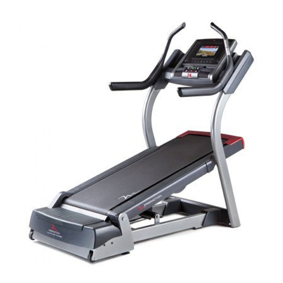
Page 6: Before You Begin
BEFORE YOU BEGIN Thank you for selecting the revolutionary reading this manual, please see the back cover of this FREEMOTION i7.9 INCLINE TRAINER. The i7.9 manual. To help us assist you, note the product model ® INCLINE TRAINER provides an impressive selection of number and serial number before contacting us. -
Page 7: Part Identification Chart
PART IDENTIFICATION CHART Use the drawings below to identify small parts used for assembly. The number in parentheses below each draw- ing is the key number of the part, from the PART LIST near the end of this manual. The number following the key number is the quantity used for assembly. -
Page 8: Assembly
ASSEMBLY • Assembly requires two persons. • Assembly requires the following tools (not included): • Place all parts in a cleared area and remove the one 3/8" hex key packing materials. Do not dispose of the packing materials until you finish all assembly steps. one 7/32" hex key • To identify small parts, see page 7. - Page 9 3. Partially tighten six 1/2" x 1" Screws (35) with four 1/2" Split Washers (49) and two 1/2" Star Washers (83) through the bracket near the right Upright (93) and into the Base Frame (56) as shown; do not tighten the Screws yet.
- Page 10 6. Set the console assembly on the Upright (93). Be care- ful not to pinch any wires. Make sure that the ends of Console the Console Crossbar (110) are inserted into the ends of Assembly the Upright. Start two 3/8" x 2 1/2" Bolts (61) with two 3/8" Flat Washers (78) into the Upright (93) as shown.
- Page 11 9. Connect the pulse wires from the Left and Right Handrail Assemblies (112, 113) to the pulse wires from the Console (103). Insert the included ties through the tie blocks attached to the back of the Console Base (109). Loop the ties around the pulse wires, the Upright Wire (116), and the Upright TV Cable (89), then tighten the ties around the wires.
- Page 12 12. See page 14 and plug in the power cord. Next, see page 18 and turn on the power. Then, press the Incline button numbered 30. 13. Press the Upright Cover (114) onto the lower end of the Upright (93) until the Upright Cover snaps into place. Lower the incline by pressing the Incline button num- bered 0 and unplug the power cord.
-
Page 13: How To Move The Incline Trainer
HOW TO MOVE THE INCLINE TRAINER Before moving the incline trainer, unplug the power cord. Note: It may be necessary to disconnect a CATV cable Do not lift on and a network wire from the incline trainer, depending on the Handrails how far the incline trainer will be moved. -
Page 14: Operation And Adjustment
OPERATION AND ADJUSTMENT HOW TO CONNECT THE POWER CORD nominal 120-volt circuit capable of carrying 15 or more amps. To avoid overloading the circuit, do Use a Surge Suppressor not plug other electrical devices, except for low- power devices such as cell phone chargers, into Your incline trainer, like other electronic equipment, the surge suppressor or into an outlet on the same circuit. - Page 15 (some satellite receivers and DVD players) will require an RF modulator to work correctly. RF modulators are not available from FreeMotion Fitness, but are avail- able at electronics stores. See the owner’s manual for the equipment you wish to connect to determine if an RF modulator is needed, or contact your local audio/ video service provider.
-
Page 16: How To Upgrade The Console
HOW TO UPGRADE THE CONSOLE Your incline trainer’s console has been preconfigured to operate with a 17" Digital TV (see the drawings below). To learn about the features of the basic console, see page 17. To learn about the features of the 17" Digital TV, see the user’s manual included with the 17"... -
Page 17: How To Use The Console
HOW TO USE THE CONSOLE FEATURES OF THE CONSOLE When you use the manual mode, you can change the speed and incline of the incline trainer with the touch of The incline trainer console offers an impressive array a button. of features designed to make your workouts more effective and enjoyable. - Page 18 HOW TO TURN ON THE POWER HOW TO USE THE TOUCH SCREEN 1. Plug in the power cord. The console features a tablet with a full-color touch screen. The following information will help you become See HOW TO CONNECT THE POWER CORD on familiar with the tablet’s advanced technology: page 14.
- Page 19 HOW TO SET UP THE CONSOLE disclaimer, touch the I Accept button, and check the medical disclaimer checkbox. Then, touch the Before using the incline trainer for the first time, set up Confirm Activation Code button. the console. Enter the requested personal information. When 1.
- Page 20 HOW TO USE THE MANUAL MODE Note: The first time you adjust the incline, you must first calibrate the incline system (see step 4 on 1. Insert the key into the console. page 27). 5. Monitor your progress. See HOW TO TURN ON THE POWER on page 18.
- Page 21 7. Turn on the fan if desired. If desired, adjust the volume by pressing the Vol increase and decrease buttons on the console. The fan features multiple speed settings and an To pause the workout, touch one of the menu but- auto mode.
- Page 22 HOW TO USE AN ONBOARD WORKOUT If the speed or incline setting is too high or too low at any time during the workout, you can override 1. Insert the key into the console. the setting by pressing the Speed or Incline but- tons;...
- Page 23 HOW TO USE A SET-A-GOAL WORKOUT The workout will function in the same way as the 1. Insert the key into the console. manual mode (see pages 20 and 21). See HOW TO TURN ON THE POWER on page The workout will continue until you reach the goal that you set.
- Page 24 HOW TO USE AN IFIT LIVE WORKOUT For more information about the iFit Live work- outs, please see www.iFit.com. Note: To use an iFit Live workout, you must have access to a wireless network (see HOW TO USE THE When you select an iFit Live workout, the screen WIRELESS NETWORK MODE on page 28).
- Page 25 HOW TO USE THE EQUIPMENT SETTINGS MODE plug in the power cord, press the power switch into the on position, and insert the key into the console. The console features an equipment settings mode However, when you remove the key, the screen will that allows you to select a language and the unit of show a demo presentation.
- Page 26 9. Set a time for the reset timeout. HOW TO USE THE ENTERTAINMENT MODE The console features an automatic reset feature; if The console features an entertainment mode that no buttons are touched or pressed and the walking allows you to connect the console to a remote TV. If belt does not move for a set amount of time, the you purchase the 17"...
- Page 27 HOW TO USE THE MAINTENANCE MODE The screen will show the progress of the update. The console features a maintenance mode that allows When the update is complete, the incline trainer will you to update the console firmware, calibrate the turn off and then turn back on.
- Page 28 HOW TO USE THE WIRELESS NETWORK MODE An information box will ask if you want to connect to the wireless network. Touch the Connect button The console features a wireless network mode that to connect to the network or touch the Cancel but- allows you to set up a wireless network connection.
- Page 29 HOW TO USE THE SOUND SYSTEM 3. iPod. To listen to music and the console audio on your per- Select this audio source to listen to your iPod (see sonal headphones or ear buds, plug the audio wire on HOW TO USE THE SOUND SYSTEM at the left). your headphones into the audio jack in the center of the lower section of the console.
-
Page 30: Preventive Maintenance
PREVENTIVE MAINTENANCE Regular maintenance is necessary for optimal performance and long life of the incline trainer. Please read and follow all instructions below. If the incline trainer is not maintained as described, components may wear excessively, the incline trainer may be damaged, and the warranty will be voided. If you have ques- tions about maintenance, please see the back cover of this manual. - Page 31 TURNING THE WALKING PLATFORM Both sides of the walking platform are designed to be used as walking surfaces. Inspect the walking platform periodically for wear. If there is any wood showing through the phenolic coating, or if the surface is damaged, the walking platform should be turned over.
- Page 32 REPLACING THE WALKING BELT When the walking belt becomes worn, it should be replaced. The walking belt will need to be replaced after every 10,000 to 15,000 miles (16,000 to 24,000 kilometers). See the Service Manual for replacement instructions. Please see the back cover of this manual to order a new walking belt. REPLACING THE WALKING PLATFORM When both sides of the walking platform become worn, the walking platform should be replaced.
-
Page 33: Six-Month Preventive Maintenance Record
SIX-MONTH PREVENTIVE MAINTENANCE RECORD Photocopy this form and use it to record the preventive maintenance performed on the incline trainer. Each copy of the form can be used for six months (26 weeks). When maintenance is performed, write the date in the appro- priate spaces. -
Page 34: Troubleshooting
TROUBLESHOOTING Most incline trainer problems can be solved by SYMPTOM: The walking belt slows when walked on following the steps below. Find the symptom that applies, and follow the steps listed. If further assis- a. If the walking belt is overtightened, performance tance is needed, please see the back cover of this may decrease and the walking belt may be dam- manual. - Page 35 SYMPTOM: The walking belt is off-center or slips belt should just touch the walking platform. Make when walked on sure to keep the walking belt centered. Then, plug in the power cord, insert the key, and run the a. If the walking belt has shifted to the right: incline trainer for a few minutes.
-
Page 36: Exercise Guidelines
EXERCISE GUIDELINES Burning Fat—To burn fat effectively, you must exer- WARNING: cise at a low intensity level for a sustained period of Before beginning this time. During the first few minutes of exercise, your or any exercise program, consult your physi- body uses carbohydrate calories for energy. - Page 37 SUGGESTED STRETCHES The correct form for several basic stretches is shown at the right. Move slowly as you stretch —never bounce. 1. Toe Touch Stretch Stand with your knees bent slightly and slowly bend forward from your hips. Allow your back and shoulders to relax as you reach down toward your toes as far as possible.
-
Page 38: Part List
PART LIST Model No. VMTL39811.0 R0112A Key No. Qty. Description Key No. Qty. Description Side Cover 5/16" x 1" Screw #8 x 1/2" Machine Screw Drive Motor Center Isolator Drive Motor Isolator 3/8" Jam Nut 3/4" x 1/2" Screw Plastic Insert... - Page 39 Key No. Qty. Description Key No. Qty. Description Filter Power Cord Controller Speed Disk Screw Console Speed Disk Console Back Cover Caution Decal Key/Clip Speed Sensor Bracket Console Back Warning Decal Console Base Back Motor Mount Bushing Console Frame Roller Insert Console Base Thrust Washer Console Crossbar...
-
Page 40: Exploded Drawing
EXPLODED DRAWING A Model No. VMTL39811.0 R0112A... - Page 41 EXPLODED DRAWING B Model No. VMTL39811.0 R0112A...
- Page 42 EXPLODED DRAWING C Model No. VMTL39811.0 R0112A...
- Page 43 EXPLODED DRAWING D Model No. VMTL39811.0 R0112A...
-
Page 44: How To Contact Customer Care
1500 South 1000 West Logan, UT 84321-9813 United States LIMITED WARRANTY FreeMotion Fitness warrants this product to be free from environments including spa and pool areas. defects in workmanship and material under normal use and 7. D amage caused by improper wiring or insufficient electrical service conditions. The warranty period commences on the current.
Need help?
Do you have a question about the VMTL39811.0 and is the answer not in the manual?
Questions and answers