Table of Contents
Advertisement
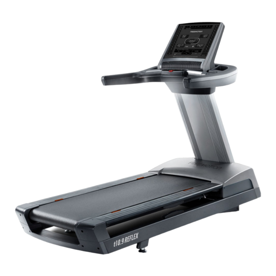
Model No. FMTL39818.0
Serial No.
USER'S MANUAL
Write the serial number in the space
above for reference.
Serial Number Decal
QUESTIONS?
If you have questions, or if parts
are damaged or missing,
please see HOW TO CONTACT
CUSTOMER CARE on the back
cover of this manual.
CAUTION
Read all precautions and instruc-
tions in this manual before using
this equipment. Save this manual
for future reference.
freemotionfitness.com
Advertisement
Table of Contents

Related Manuals for Freemotion t10.9 REFLEX


Summary of Contents for Freemotion t10.9 REFLEX
- Page 1 Model No. FMTL39818.0 Serial No. USER’S MANUAL Write the serial number in the space above for reference. Serial Number Decal QUESTIONS? If you have questions, or if parts are damaged or missing, please see HOW TO CONTACT CUSTOMER CARE on the back cover of this manual.
-
Page 2: Table Of Contents
LIMITED WARRANTY............. . . Back Cover FREEMOTION is a registered trademark of ICON Health & Fitness, Inc. -
Page 3: Warning Decal Placement
WARNING DECAL PLACEMENT These drawings show the locations of the warning decals. If a decal is missing or illegible, see the back cover of this manual and request a free replacement decal. Apply the decal in the location shown. Note: The decals may not be shown at actual size. -
Page 4: Important Precautions
To reduce the risk of burns, fire, electric shock, or injury to persons, read all important precautions and instructions in this manual and all warnings on your treadmill before using your treadmill. FreeMotion Fitness assumes no responsibility for personal injury or property damage sustained by or through the use of this product. - Page 5 DANGER: 21. Do not move the treadmill until it is properly Always unplug the power assembled (see ASSEMBLY on page 8). Do cord immediately after use, before clean- not move the treadmill by sliding it (see HOW ing the treadmill, and before performing the TO MOVE THE TREADMILL on page 19).
-
Page 6: Before You Begin
BEFORE YOU BEGIN Thank you for selecting the revolutionary reading this manual, please see the back cover of this FREEMOTION T 10.9 REFLEX treadmill. The manual. To help us assist you, note the product model ® T 10.9 REFLEX treadmill offers an impressive selec- number and serial number before contacting us. -
Page 7: Part Identification Chart
PART IDENTIFICATION CHART Use the drawings below to identify small parts used for assembly. The number in parentheses below each draw- ing is the key number of the part, from the PART LIST near the end of this manual. The number following the key number is the quantity used for assembly. -
Page 8: Assembly
ASSEMBLY • Assembly requires two persons. • Assembly requires the following tools: one set of English hex keys • Place all parts in a cleared area and remove the packing materials. Do not dispose of the packing one adjustable wrench materials until you finish all assembly steps. - Page 9 2. Insert the end of the Upright Wire (111) through the looped plastic tie (A) at the top of the Upright (81). Make sure that the Upright Wire is behind the crossbars (C) on the Upright. Then, gently pull upward on the Upright Wire as you tighten the plastic tie around the Upright Wire.
- Page 10 4. Have a second person hold the handrail assem- bly (E) near the Upright (81). Insert the Upright Wire (111) upward through the center of the handrail assembly. Then, slide the bracket (F) on the handrail assembly (E) over the crossbar (C) on the Upright (81), and set the handrail assembly on the Upright.
- Page 11 6. Tighten two 3/8" x 4" Screws (11) with two 3/8" Flat Washers (43) into the handrail assembly (E); start both Screws, and then torque them to 20 pound-feet (27 Newton-meters). See step 5. Torque the two 3/8" x 4" Screws (11) to 20 pound-feet (27 Newton-meters).
- Page 12 8. Tighten four 3/8" x 2 3/4" Screws (27) with two 3/8" Star Washers (2) into the handrail assembly (E). 9. Attach the Upright Collar (105) to the handrail assembly (E) with two #8 x 5/8" Screws (18).
- Page 13 10. If necessary, move the treadmill to the desired location. IMPORTANT: Before moving the treadmill, see HOW TO MOVE THE TREADMILL on page 19. After the treadmill is placed in the location where it will be used, make sure that the Leveling Feet (64) rest firmly on the floor.
-
Page 14: How To Use The Treadmill
Canada) and are then subject to the terms pro- electric shock. vided by that country’s local authorized FreeMotion Fitness, Inc. representative. This product is for use on a dedicated, 20-amp, 120-volt circuit. -
Page 15: How To Use The Console
HOW TO USE THE CONSOLE FEATURES OF THE CONSOLE Note: The console can display speed and distance in either miles or kilometers. To find which unit of mea- The treadmill console offers a selection of features surement is selected, see THE MAINTENANCE MODE designed to make your workouts more effective and on page 18. - Page 16 HOW TO TURN ON THE POWER HOW TO USE THE MANUAL MODE IMPORTANT: If the treadmill has been exposed to 1. Insert the key into the console. cold temperatures, allow it to warm to room tem- perature before you turn on the power. If you do See HOW TO TURN ON THE POWER at the left.
- Page 17 5. Follow your progress with the displays. 7. Turn on the fan if desired. The matrix—The matrix The fan features several will display a track that speed settings and an represents 1/4 mile auto mode. When the (400 meters). As you auto mode is selected, the ETFM39818 exercise, the indicators...
- Page 18 CALIBRATE INCL—This display is used to calibrate The workout will continue until you reach the goal that you set. The treadmill will then enter cool down the incline system. To calibrate the incline system, mode, after which the walking belt will slow to a press the Incline increase and decrease buttons.
-
Page 19: How To Move The Treadmill
HOW TO MOVE THE TREADMILL IMPORTANT: Due to the size and weight of the 2. When the treadmill is in the location where it will be treadmill, moving it requires two or three persons. used, make sure that the leveling feet rest firmly To avoid damaging the leveling feet, do not move on the floor. -
Page 20: Preventive Maintenance
PREVENTIVE MAINTENANCE Regular maintenance is necessary for optimal perfor- MONTHLY MAINTENANCE mance and long life of the treadmill. Please read and 1. Remove the key and unplug the power cord. follow all instructions below. If you have questions, see the back cover of this manual. Next, remove the two indicated 5/16"... - Page 21 REPLACING THE WALKING PLATFORM AND THE 3. Remove the two 1/4" x 3/4" Cap Screws (15), the WALKING BELT two 3/8" Hairpin Cotter Pins (26), the two 3/8" Pins (14), and the two 3/8" Washers (32). Inspect the walking platform periodically for wear. If Next, remove the two 3/8"...
- Page 22 5. Remove the Walking Belt (46) and the Walking 6. Lift the right or left edge of the Walking Belt (46) Platform (44) from the treadmill. Next, remove the and look for a small arrow printed on the under- Walking Belt from the Walking Platform. Then, side of the Walking Belt;...
- Page 23 LUBRICATING THE WALKING BELT 7. Center the Walking Belt (46), if necessary (see page 25). Then, plug in the power cord, step onto the foot rails, insert the key into the console, and Your treadmill features a walking belt coated with high- performance lubricant.
-
Page 24: Preventive Maintenance Record
PREVENTIVE MAINTENANCE RECORD Photocopy this form and use it to record the preventive maintenance performed on the treadmill. Each copy of the form can be used for six months (26 weeks). When maintenance is performed, write the date in the appropriate spaces. -
Page 25: Troubleshooting
TROUBLESHOOTING MAINTENANCE SYMPTOM: The power turns off during use Regular maintenance is important for optimal perfor- a. Check the power switch (see drawing c at the left). mance and to reduce wear. Inspect and properly tighten If the switch has tripped, wait for five minutes and all parts each time the treadmill is used. - Page 26 b. If the walking belt slips when walked on, first remove the key and UNPLUG THE POWER CORD. To properly tighten the walking belt, see step 7 on page 23.
-
Page 27: Exercise Guidelines
EXERCISE GUIDELINES Burning Fat—To burn fat effectively, you must exer- WARNING: cise at a low intensity level for a sustained period of Before beginning this time. During the first few minutes of exercise, your or any exercise program, consult your physi- body uses carbohydrate calories for energy. - Page 28 SUGGESTED STRETCHES The correct form for several basic stretches is shown at the right. Move slowly as you stretch —never bounce. 1. Toe Touch Stretch Stand with your knees bent slightly and slowly bend forward from your hips. Allow your back and shoulders to relax as you reach down toward your toes as far as possible.
- Page 29 NOTES...
-
Page 30: Part List
PART LIST Model No. FMTL39818.0 R1117A Key No. Qty. Description Key No. Qty. Description 3/8" x 3 1/4" Screw #16 x 1 1/2" Screw 3/8" Star Washer Converter Board #8 x 5/8" Machine Screw Frame #8 x 3/8" Machine Screw Drive Motor 3/8"... - Page 31 Key No. Qty. Description Key No. Qty. Description Console Assembly 1/2" Standoff Rear Resistor Bracket #8 x 3/4" Washer Head Screw Resistor #6 x 1/2" Screw Front Resistor Bracket Right Cap Insert Bracket Upright Collar Fan Grill #8 x 2" Screw Switch Bracket Key/Clip Wheel Bushing...
-
Page 32: Exploded Drawing
EXPLODED DRAWING A Model No. FMTL39818.0 R1117A... - Page 33 EXPLODED DRAWING B Model No. FMTL39818.0 R1117A 104 9...
- Page 34 EXPLODED DRAWING C Model No. FMTL39818.0 R1117A...
- Page 35 EXPLODED DRAWING D Model No. FMTL39818.0 R1117A...
-
Page 36: How To Contact Customer Care
WARRANTY PERIODS AND COVERAGE 2. Pick-up, delivery, or freight charges involved with a repair. FreeMotion Fitness warrants this product to be free from 3. Any problem as a result of improper assembly or delivery. defects in workmanship and material under normal use and WHAT TO DO IF SERVICE IS REQUIRED service conditions.
Need help?
Do you have a question about the t10.9 REFLEX and is the answer not in the manual?
Questions and answers