Weinmann MEDUMAT Easy CPR Instructions For Use Manual
Hide thumbs
Also See for MEDUMAT Easy CPR:
- Instructions for use manual (148 pages) ,
- Service and repair instructions (60 pages) ,
- Description and instructions for use (76 pages)

Related Manuals for Weinmann MEDUMAT Easy CPR


Summary of Contents for Weinmann MEDUMAT Easy CPR
- Page 1 MEDUMAT Easy Ventilator Instructions for use for devices from Serial Number 25000 or software version 29 Read these instructions for use before using this product. Failure to do so can result in serious injury or death.
-
Page 2: Table Of Contents
Table of Contents Table of Contents Information on these instructions for use Copyright protection ..............5 Customer Service ................6 Warning notices in these instructions for use ......... 6 Safety Intended use ................. 8 Personnel requirements ..............9 Preventing a device failure ............10 Ensuring good hygiene practices .......... - Page 3 Table of Contents Checking device functions ............43 Operation Preparing for ventilation .............. 53 Setting the ventilation parameters ..........58 Switching the device on ............... 61 Ventilating the patient ..............62 Muting alarms ................68 Switching the device off .............. 69 Disassembly Disassembling the ventilation mask and tube .......
- Page 4 Table of Contents Scope of supply, replacement parts and accessories 12.1 Standard scope of supply ............101 12.2 Accessories ................102 12.3 Replacement parts ..............102 Technical data 13.1 Device ..................103 13.2 Breathing circuit ................ 106 13.3 Protective transport bag ............106 13.4 Pneumatic system diagram ............
-
Page 5: Information On These Instructions For Use
WEINMANN Emergency Medical Technology GmbH + Co. KG (referred to below as the "manufacturer"). Infringements will lead to liability for damages. The manufacturer reserves the right to assert further claims. -
Page 6: Customer Service
1 Information on these instructions for use 1.2 Customer Service Should you have any questions, the WEINMANN Emergency LP Customer Service will be delighted to be of assistance: WEINMANN Emergency LP 5126 South Royal Atlanta Drive Address Tucker, GA 30084 E-mail info@weinmann-emergency.com... - Page 7 1 Information on these instructions for use Example of an embedded warning notice: 1. Undo screw. CAUTION! Risk of pinching on lid! Carefully close the lid. 3. Tighten the screw. MEDUMAT Easy...
-
Page 8: Safety
2 Safety Safety The instructions for use are part of the device. If the instructions for use and the following safety information are not fully complied with, the treatment may fail or be compromised. This could cause severe or life-threatening injuries to the patient and user. ... -
Page 9: Personnel Requirements
2 Safety Contraindications None currently known. Possible side effects and complications • Undesirable effects on the cardiovascular system (e.g., reduction of cardiac output, reduction of venous return flow) • Drying out of the airways • Overinflation of the lung tissue (lung rupture) •... -
Page 10: Preventing A Device Failure
2 Safety 2.3 Preventing a device failure 2.3.1 Pay attention to the correct ambient conditions If the device or accessories are operated in a non-specified environment, the treatment may be compromised as a result of malfunctions. Do not operate the device and accessories outside of the specified ambient conditions (see "13.1 Device", page 103). -
Page 11: Ensuring Good Hygiene Practices
2 Safety 2.3.4 Do not perform any modifications to the construction of the device or accessories If modifications are performed to the construction of the device or accessories, the treatment may be compromised as a result of malfunctions. Do not perform any modifications to the construction of the device or accessories. -
Page 12: Safe Use Of The Device And Accessories
Do not stack the device with other electrical devices. Do not operate the device directly next to other electrical devices. Exception: Other WEINMANN Emergency devices which have been tested and shown to guarantee interference- free operation with the adjacent device. A list of other devices is available on request. - Page 13 Only use approved accessories. Only use spare parts from WEINMANN Emergency or spare parts that have been approved by WEINMANN Emergency. MEDUMAT Easy...
- Page 14 2 Safety 2.5.6 Monitoring the patient and the device If alarm lights and loudspeakers are covered up, the personnel will not be able to see or hear the alarms and will therefore not be able to respond to dangerous situations. ...
- Page 15 2 Safety Before working on the oxygen supply, wash your hands in order to remove any oil or grease. Secure the oxygen cylinder so that it cannot fall over. Tighten or loosen all screwed unions on the oxygen cylinder and on the pressure reducer by hand only.
- Page 16 2 Safety Do not open the battery and do not deform the battery. Do not recharge the battery. Do not short circuit the battery. Protect the battery from moisture. Do not expose the battery to high pressures. ...
-
Page 17: Description
3 Description Description 3.1 Overview of device and accessories 3-1 Device and accessories Designation Description The device ventilates the patient. MEDUMAT Easy Pressure measuring tube Measures the ventilation pressure. Mounting set with retaining Serves to secure the device onto a pole or stretcher. plate and fastening strap Ventilation hose Conducts oxygen from the device to the patient. -
Page 18: Description Of Device Functionality
3 Description Designation Description Breathing system filter* Cleans and air-conditions the respiratory air. Instructions for use Serve to ensure safe use of the device. Connects the patient to be ventilated with the breathing Tube* circuit. Connects the patient to be ventilated with breathing Ventilation mask* circuit. -
Page 19: Accessories
3 Description 3.3 Accessories 3.3.1 Breathing circuit 3-2 Breathing circuit The ventilation gas is delivered to the patient via the breathing circuit.The breathing circuit comprises a pressure measuring tube (1), a ventilation hose (2) and the patient valve. Both hoses are connected to the patient valve and the device. - Page 20 3 Description 3.3.2 MEDUtrigger 3-3 MEDUtrigger MEDUtrigger serves to trigger individual mechanical breaths with the set tidal volume. In this way, you determine the respiratory rate administered yourself. The mechanical breaths are triggered by actuating the button (3) on MEDUtrigger. The two LEDs (1 and 2) on MEDUtrigger show the current operating status.
- Page 21 3 Description The PEEP valve enables ventilation with a positive end-expiratory pressure (PEEP). The PEEP valve prevents the pressure dropping to the ambient air pressure during expiration. Attach the PEEP valve to the expiration side of the patient valve. The PEEP valve is not included in the purchase of the device. 3.3.4 Tube 3-5 Tube The tube can be used in addition to the ventilation mask for patient...
- Page 22 3 Description The ventilation mask is used for non-invasive ventilation. The ventilation mask is not included in the purchase of the device. 3.3.6 Breathing system filter 3-7 Breathing system filter Commercially available HME breathing system filters (HME = Heat Moisture Exchange) with standard connections (15/22 mm) can be attached to the inspiration side of the patient valve to filter and air-condition the respiratory air.
- Page 23 3 Description The testing bag (1) serves to check the functionality of the device prior to use. During testing, the testing bag simulates the human lung. The connector (2) is connected to the patient valve for the function check. 3.3.8 Low-pressure hose assembly 3-9 Low-pressure hose assembly The low-pressure hose assembly connects the device to the oxygen supply.
- Page 24 3 Description 3.3.9 Mounting set with retaining plate and fastening strap 3-10 Mounting set with retaining plate and fastening strap The mounting set serves to temporarily secure the device to the site of use. It comprises a retaining plate (3), screws (1), and a fastening strap with a safety lock (2).
-
Page 25: Connections And Interfaces
3 Description 3.4 Connections and interfaces p M a x (c p M a x (c p M a x (c 3-11 Connections and interfaces Designation Description Compressed gas connection Connects the oxygen supply to the device. Battery compartment Houses the battery. Loudspeaker Emits audible alarms. -
Page 26: Control Panel
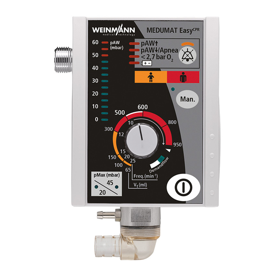
3 Description 3.5 Control panel pMax (cmH 3-12 Control panel Designation Description Ventilation pressure display Displays the ventilation pressure in cmH Indicates alarm states visually. • LED is lit: Alarm is active. Alarm field with alarm lights • LED is not lit: Alarm is not active. Indicates the status of alarm muting. -
Page 27: Labels And Symbols
3 Description Designation Description Visually displays the status of the demand flow mode. • Illuminated: The demand flow mode is switched on. LED demand flow • Not illuminated: The demand flow mode is switched off. On/Off button Switches the device on or off. Switches between the ventilation pressure limit for mask pMax button with control LEDs ventilation (20 cmH... - Page 28 3 Description Symbol Description Fragile Can be used up to YYYY-MM-DD Free from natural rubber latex Do not dispose of device in household waste Type BF applied part Protection class II, protective insulation Protection against the ingress of dust and splash water from IP54 all sides Software-Version:...
-
Page 29: Ventilation Modes
3 Description Symbol Description Pull out the plug vertically and do not turn WM 28110 Adhesive label with article number and flow direction arrows Patient UDI marking - possible application identifiers: (01): Global Trade Item Number (GTIN) - globally unique Identification Number (10): Batch/Lot Number (xx)xxxxxxxxxxxxxx (xx)xxxxx... - Page 30 3 Description 3.7.2 Manual mode In the manual mode the user can adjust the breathing rate by himself. It can only be activated when MEDUtrigger is connected. MEDUtrigger can be used to deliver manual breaths to the patient with the set tidal volume. For example, manual mode is used to check the tube after intubation or for cardiopulmonary resuscitation.
-
Page 31: Preparation
4 Preparation Preparation 4.1 Unpacking the delivery and visual inspection 1. Remove the packaging material. 2. Recycle the packaging material and dispose of properly. 3. Check the delivery to ensure nothing is missing (see "12.1 Standard scope of supply", page 101). - Page 32 4 Preparation 1. Position the red marking on the fastening strap (1) onto the red recess on the retaining plate (2). 2. Insert the ends of the fastening strap into the depressions on the retaining plate. MEDUMAT Easy...
- Page 33 4 Preparation 3. Screw the retaining plate onto the device by turning the supplied screws clockwise. 4. Place the fastening strap around the desired piece of equipment. 5. Close the safety lock on the fastening strap. To do so, connect the two buckles until they securely lock into place.
-
Page 34: Connecting An Oxygen Supply
4 Preparation 4.3 Connecting an oxygen supply Risk of fire and explosion due to highly compressed oxygen combined with hydrocarbon compounds! Hydrocarbon compounds (e.g., oil, grease, cleaning alcohol, hand cream or adhesive plasters) can cause explosive reactions if they come into contact with highly compressed oxygen. This can result in severe or life-threatening injury to the patient, user or bystanders. - Page 35 4 Preparation 2. Tighten the pressure reducer using the handwheel (1 ). To do this, turn the handwheel clockwise. 3. Connect the low-pressure hose assembly (3) to the pressure reducer (1) or the central gas supply using the union nut (2) or quick-release coupling.
-
Page 36: Connecting The Breathing Circuit And Medutrigger To The Device
4 Preparation p M ax (c Image swapped (USA variant) 4. Connect the other end of the low-pressure hose assembly to the device using the union nut. To do this, screw the union nut onto the device’s compressed gas connection in a clockwise direction. - Page 37 4 Preparation p M a x (c 2. Grasp the end of the ventilation hose (2) and push onto the connection. If necessary: Turn the ventilation hose (2) slightly to avoid bending the pressure measuring tube (1). p M a x (c 3.
- Page 38 4 Preparation 4. Connect the MEDUtrigger cable to the breathing circuit using the clips. CAUTION! Delayed treatment due to incorrect position of MEDUtrigger on the patient valve! Push MEDUtrigger fully onto the inspiration side of the patient valve. Result The breathing circuit and MEDUtrigger are connected. The device is now ready for the function check (see "5 Function check", page...
-
Page 39: Function Check
(see "9.2 Faults", page 93). If you are unable to rectify the faults using the table, please contact WEINMANN Emergency or a technician who has been expressly authorized by WEINMANN Emergency promptly. Devices and accessories which are defective or not ready for... -
Page 40: Visually Checking The Device And Accessories
5 Function check 5.2 Visually checking the device and accessories Requirement The device is switched off (see "6.6 Switching the device off", page 69). 1. Check the device and accessories for external damage. 2. Carefully bend the MEDUtrigger cable and check for: •... -
Page 41: Preparing For The Function Check
5 Function check 5.3 Preparing for the function check Required material Oxygen supply Requirement The device and accessories have been checked visually and are in perfect condition (see "5.2 Visually checking the device and accessories", page 40). 1. Connect the device to the oxygen supply (see "4.3 Connecting an oxygen supply", page 34). - Page 42 5 Function check 2. Read off the oxygen cylinder pressure on the contents gauge (1) of the pressure reducer. 3. Close the oxygen cylinder. 4. Monitor the needle on the contents gauge (1) on the pressure reducer for 1 minute. •...
-
Page 43: Checking Device Functions
5 Function check 5.5 Checking device functions In order to perform the function check comprehensively and rapidly, check all functions in succession in the order below. Risk of injury from improperly removed testing bag for function check! If the testing bag is removed improperly, the connector of the testing bag may remain on the breathing circuit. - Page 44 5 Function check 2. Connect the testing bag for function check up to the patient valve. 3. Switch on the device using the On/Off button. Upon being switched on, the device performs an automatic self-test which takes approx. 2 seconds. 4.
- Page 45 5 Function check pMax (cmH • Check whether the bottom most LED on the ventilation pressure display (7) lights up green. • Check that the LED (8) for the alarm goes out and that the device commences ventilation in the correct manner.
- Page 46 5 Function check p M ax (c 6. Press the alarm mute button again. • Check that the alarm mute LED goes out. Result The visual and audio alarm output has been checked. 5.5.2 Checking the supply pressure alarm 1. Close the oxygen cylinder. •...
- Page 47 5 Function check 1:00 min 23-27 2. Count the number of inspiration phases for exactly 1 minute. • Check whether the ventilation rate is between 23 bpm and 27 bpm. In combination with the testing bag for function check, these settings can cause the pAW Apnea alarm to be triggered.
- Page 48 5 Function check 2. Simulate the expiration phase by hand with the testing bag. To this end, place the testing bag on a firm surface and, during the expiration phase, press on the testing bag with your hand flat until the volume has been completely discharged via the patient valve.
- Page 49 5 Function check CAUTION! Risk of injury from improperly removed testing bag for function check! Remove the testing bag from the patient valve. • Check whether the device triggers the pAW Apnea alarm after the second inspiration breath. 5. Connect the testing bag back up to the patient valve. Result The tidal volume and airway pressure measurement have been checked.
- Page 50 5 Function check p M ax (c 2. Press the Man. button. • Check whether the control LED on the Man. button lights • Check whether both LEDs on MEDUtrigger light up. 3. Press the button on MEDUtrigger (1). • Check whether a mechanical breath is triggered.
- Page 51 5 Function check 5.5.6 Checking the demand flow mode p M ax (c 1. Select the "demand flow" setting. To do this, turn the adjusting knob for ventilation parameters clockwise past the snap-in position (1). • Check whether the green demand flow LED (2) lights up. 2.
- Page 52 5 Function check • Check whether the device switches the flow on and immediately off again. You can hear a slight click. 3. Switch off the device using the On/Off button. To do this, keep the On/Off button depressed until all 4 alarm LEDs light up. Then release the On/Off button.
-
Page 53: Operation
6 Operation Operation 6.1 Preparing for ventilation Requirement • The device and accessories have been cleaned and disinfected (see "8 Cleaning and disinfection", page 79). • The device is ready for use (see "4 Preparation", page 31). • The function check is complete (see "5 Function check", page 39). - Page 54 6 Operation 2. Open the oxygen cylinder slowly. The contents gauge (1) displays the oxygen cylinder pressure. 3. Calculate the remaining operating time to ensure that the device does not stop unexpectedly (see "14 Appendix", page 110). 4. Connect accessories. •...
- Page 55 6 Operation 1. Connect the ventilation mask (1) together with MEDUtrigger (2) on the patient valve (3). Connect the tube (1) together with MEDUtrigger (2) on the patient valve (3). 2. Check whether MEDUtrigger has been pushed down fully on the patient valve.
- Page 56 6 Operation 6.1.2 Connecting the breathing system filter Fault or treatment failure due to incompatibility of the device with consumables, accessories or other medical devices! Defective and unauthorized accessories can result in malfunctions, increased electromagnetic interference emissions and reduced electromagnetic immunity of the device, incorrect output values and reduced ventilation performance.
- Page 57 6 Operation 2. Connect the breathing system filter (3) to the patient connection of the patient valve (4). 3. Connect MEDUtrigger (2) to the breathing system filter (3). 4. Connect the ventilation mask (1) to MEDUtrigger (2). Result The breathing system filter is ready for mask ventilation. Connecting the breathing system filter for tube ventilation 1.
-
Page 58: Setting The Ventilation Parameters
6 Operation 3. Connect MEDUtrigger (2) to the breathing system filter (3). 4. Following intubation, connect the tube (1) to MEDUtrigger (2). Result The breathing system filter is ready for tube ventilation. 6.1.3 Connecting the PEEP valve 1. Observe the instructions for use from the PEEP valve manufacturer. - Page 59 6 Operation 6.2.1 Setting the respiratory rate and tidal volume p M ax (c 1. Set the tidal volume Vt and the associated respiratory rate. To do this, turn the adjusting knob for ventilation parameters. Result The respiratory rate and tidal volume are set. Assignment of the ventilation parameters Orange Age (in years)
- Page 60 6 Operation 6.2.2 Setting the maximum ventilation pressure Requirement The device is switched on (see "6.3 Switching the device on", page 61). pMax (cmH pM ax (c 1. Set the ventilation pressure. To do this, press the pMax button with control LEDs. The associated LED displays the set maximum ventilation pressure.
-
Page 61: Switching The Device On
6 Operation 6.3 Switching the device on p M ax (c 1. Switch on the device using the On/Off button. Upon being switched on, the device performs an automatic self-test which takes approx. 2 seconds. During the self-test, all the LEDs in the alarm field flash and a brief audible alarm sounds. -
Page 62: Ventilating The Patient
6 Operation 6.4 Ventilating the patient Impaired treatment due to increased breathing effort! If the expiration side and/or the spontaneous respiration side with emergency air membrane is partially or completely blocked, the breathing effort required of the patient increases and impairs treatment. - Page 63 6 Operation 2. Switch on the device (see "6.3 Switching the device on", page 61). 3. Place the ventilation mask on the mouth and nose. Hold the ventilation mask firmly in place. • With inspiration (triggering): Flow is switched on. •...
- Page 64 6 Operation 6.4.2 Ventilating the patient in manual mode Lack of treatment due to the attempt to trigger manual breaths in demand mode and continuous mode! If the device is not in manual mode and MEDUtrigger is not connected, the device/user cannot manually trigger mechanical breaths.
- Page 65 6 Operation If the button on MEDUtrigger is pressed and the manual mode is not activated, an information tone sounds. This occurs, for example, if the Man. button or the button on MEDUtrigger is pressed in demand flow mode. 2. If necessary: Place the ventilation mask on the mouth and nose. Hold the ventilation mask firmly in place.
- Page 66 6 Operation 2. Activate the demand flow mode (see "6.4.1 Ventilating the patient in demand flow mode", page 62) 3. Switch off the device (see "6.6 Switching the device off", page 69). Result The manual mode is switched off. 6.4.3 Ventilating the patient in continuous mode Switching on continuous mode Requirement •...
- Page 67 6 Operation 6.4.4 Monitoring the patient Risk of incorrect treatment due to insufficient patient monitoring! If the patient and device are not supervised and monitored during ventilation, delayed responses of medical personnel to alarms and error messages may result in serious or life-threatening injuries to the patient and to incorrect treatment.
-
Page 68: Muting Alarms
6 Operation 6.5 Muting alarms 6.5.1 Activating alarm mute function When an alarm is emitted, you can suppress the alarm tone for a maximum of 120 seconds. The exception to this is the supply pressure alarm < 40 psi O . -
Page 69: Switching The Device Off
6 Operation • The orange LED above the alarm mute button lights up. p M ax (c 1. Press the alarm mute button. Result • The alarm mute function is deactivated. • The orange LED goes out. 6.6 Switching the device off Requirement The device is switched on. -
Page 70: Disassembly
7 Disassembly Disassembly 7.1 Disassembling the ventilation mask and tube Damage to the hose system or MEDUtrigger as a result of incorrect handling! Carelessly grasping and pulling off the breathing circuit at the wrong point can result in damage to the system. ... -
Page 71: Disassembling The Breathing System Filter
7 Disassembly Disassembling the tube and MEDUtrigger 1. Pull the tube (1) and MEDUtrigger (2) off the patient valve (3). Result The tube and MEDUtrigger are disassembled. 7.2 Disassembling the breathing system filter Requirement The ventilation mask or tube is disassembled (see "7.1 Disassembling the ventilation mask and tube", page 70). -
Page 72: Disassembling The Peep Valve
7 Disassembly 7.3 Disassembling the PEEP valve 1. Pull off the PEEP valve (2) from the expiration side (1) of the patient valve. Result The PEEP valve is disassembled. 7.4 Disconnecting the breathing circuit and MEDUtrigger from the device Requirement •... - Page 73 7 Disassembly p M a x (c 1. NOTICE! Material damage caused by twisting MEDUtrigger connector back and forth! Pull the MEDUtrigger connector out of the MEDUtrigger connection. To do this, grasp the grooved part of the connector and pull it straight out of the socket without turning. 2.
- Page 74 7 Disassembly p M a x (c 3. NOTICE! Material damage from pulling out the tubes incorrectly! Grasp the end of the ventilation hose (1) and pull out of the ventilation hose connection on the device. p M a x (c 4.
-
Page 75: Removing The Oxygen Supply
7 Disassembly 7.5 Removing the oxygen supply Requirement • The device is switched off (see "6.6 Switching the device off", page 69). • The oxygen supply is closed. 1. NOTICE! Material damage due to the disconnection of a non-ventilated system! Switch on the device using the On/Off button. -
Page 76: Disconnecting The Retaining Plate And Fastening Strap From The Device
7 Disassembly 4. Disconnect the pressure reducer using the handwheel (1 ). To do this, turn the handwheel counterclockwise. 5. Disconnect the pressure reducer from the oxygen cylinder. For this, pull the pressure reducer off the oxygen cylinder valve. Result The oxygen supply is removed. - Page 77 7 Disassembly 1. Hold the device securely and open the safety lock on the fastening strap. To do so, actuate both side levers at the same time and disconnect the buckles. 2. Remove the retaining plate. To do this, turn the screws counterclockwise out of the device.
- Page 78 7 Disassembly 3. Remove the ends of the fastening strap from the depressions on the retaining plate. Result The retaining plate and fastening strap are removed. MEDUMAT Easy...
-
Page 79: Cleaning And Disinfection
8 Cleaning and disinfection Cleaning and disinfection The following sections describe the activities required for cleaning and disinfection. If you have any queries on cleaning and disinfection, please contact our Customer Service (see "1.2 Customer Service", page 8.1 Intervals Perform cleaning and disinfection at the following intervals: Part Interval After each use... - Page 80 8 Cleaning and disinfection Machine Manual Wipe Immersion Steam Part cleaning and cleaning disinfection disinfection sterilization disinfection Device Wipe down with Retaining plate ® CIDEZYME Low-pressure hose Enzymatic Wipe down assembly Detergent with Solution Super Sani- ® (Johnson& Cloth Johnson) Disposable Not permitted Not permitted...
-
Page 81: Performing Cleaning And Disinfection
8 Cleaning and disinfection 8.3 Performing cleaning and disinfection Risk of explosion due to ingress of liquids in combination with oxygen! The ingress of liquids can result in explosion and cause serious or life-threatening injuries to the patient, user or bystanders. ... - Page 82 8 Cleaning and disinfection Material damage due to the ingress of liquids! The device is protected against the ingress of water. This only applies when the battery compartment is closed. The ingress of liquids may cause damage to the device and accessories. ...
- Page 83 8 Cleaning and disinfection CAUTION! Risk of injury and damage to the device as a result of unsatisfactory hygienic reliability! Detach the fastening strap from the retaining plate (see "7.6 Disconnecting the retaining plate and fastening strap from the device", page 76).
- Page 84 8 Cleaning and disinfection 2. The cleaning agents, doses, and exposure time for the individual parts can be found in the cleaning and disinfection plan (see "8.2 Cleaning and disinfection plan", page 79). 3. Prepare the cleaning solution in accordance with the specifications of the cleaning agent manufacturer.
- Page 85 8 Cleaning and disinfection • Use a new cloth for each cleaning procedure. • All surfaces must be wiped down carefully. • All surfaces must be wetted with cleaning solution. • Ensure compliance with the exposure time specified in the cleaning and disinfection plan.
- Page 86 8 Cleaning and disinfection CAUTION! Risk of injury due to disinfectant or cleaning agent residues in the device or hose system! Allow all parts to dry fully at room temperature. Result The parts are manually cleaned. 8.3.3 Wipe disinfection Requirement •...
- Page 87 8 Cleaning and disinfection • Sufficiently wet any uneven surfaces and grooves (e.g., adjusting knob, connection for ventilation hose) with the disinfectant. • Ensure compliance with the exposure time specified in the cleaning and disinfection plan. CAUTION! Risk of injury due to disinfectant or cleaning agent residues in the device or hose system! Allow the parts to dry fully.
- Page 88 8 Cleaning and disinfection 8.3.4 Immersion disinfecting parts Requirement • The parts intended for immersion disinfection have been manually cleaned (see "8.3.2 Cleaning parts manually", page 83). 1. The parts approved for immersion disinfection can be found in the cleaning and disinfection plan (see "8.2 Cleaning and disinfection plan", page 79).
- Page 89 8 Cleaning and disinfection CAUTION! Risk of injury due to disinfectant or cleaning agent residues in the device or hose system! Rinse parts thoroughly in water with dringing water quality for at least 10 seconds after the specified exposure time to remove all disinfectant residues.
-
Page 90: Alarms And Error Messages
9 Alarms and error messages Alarms and error messages The device’s alarm system is based on the concept of self- preserving alarms. The device emits an alarm for as long as the cause continues to exist. Once the cause of the alarm no longer exists, the device no longer emits the alarm. - Page 91 9 Alarms and error messages To be Alarm Possible cause Remedy remedied by Airway obstruction Remove obstruction. User Reduced lung Reduce tidal volume. User compliance Tidal volume set Reduce tidal volume. User too high Ventilation mask/tube Remove kink or blockage; User kinked or blocked if necessary, replace the accessory.
- Page 92 9 Alarms and error messages To be Alarm Possible cause Remedy remedied by • Release the MEDUtrigger button Defective • Check MEDUtrigger MEDUtrigger/ MEDUtrigger button • If possible, switch to continuous User continually pressed in mode (see 6.4.3, p. 66) manual mode •...
-
Page 93: Faults
9 Alarms and error messages To be Alarm Possible cause Remedy remedied by Remove the battery from the battery compartment and re-insert (see 10.3, 97). Before re-inserting the battery, Device it must be ensured that the acoustic malfunction/ and visual alarms are no longer active. device failure If necessary: Repeat the procedure User/manufacturer... - Page 94 9 Alarms and error messages To be Fault Possible cause Remedy remedied by Battery empty • Change the battery in the battery compartment (see 10.3, p. 97). User/manufacturer or • If the device does not work after Incompatible battery authorized technician Device cannot be inserted changing the battery, have the...
- Page 95 9 Alarms and error messages To be Fault Possible cause Remedy remedied by Wait to trigger the breath until the Mechanical breath expiration phase has passed. The was triggered during length of the expiration phase User the expiration phase corresponds to the length of the inspiration phase.
-
Page 96: Maintenance
10 Maintenance 10 Maintenance Fault or treatment failure due to insufficient or incorrect maintenance! Incorrect maintenance can lead to dangerous situations and failure or malfunctioning of the device. This can result in severe or life-threatening injury to the patient and bystanders. ... -
Page 97: Sending The Device In For Maintenance
10 Maintenance 10.2 Sending the device in for maintenance Risk of infection and contamination due to inadequate hygienic safety during maintenance measures! The device and accessories may be contaminated, and infect the technicians or bystanders with bacteria or viruses. Carry out cleaning and disinfection of the device and accessories prior to all maintenance. - Page 98 The 3.6 V battery is a special battery. Only use WEINMANN Emergency batteries as there is otherwise a risk of premature functional failure due to the reduced battery life of third-party batteries. This can result in serious or life-threatening injury to the patient.
-
Page 99: Transport, Storage And Disposal
11 Transport, storage and disposal 11 Transport, storage and disposal 11.1 Transporting the device The protective transport bag from WEINMANN Emergency is available for transporting the device. 11.2 Storing the device Material damage due to incorrectly stored breathing circuit (disposable)! Material changes can result from incorrect storage of the breathing circuit. -
Page 100: Disposal
11 Transport, storage and disposal 11.3 Disposal 11.3.1 Electronic waste Do not dispose of the product in the household waste. Consult an authorized, certified electronic waste recycling company for proper disposal. You can find out their address from your environmental officer or from your local council. -
Page 101: Scope Of Supply, Replacement Parts And Accessories
12 Scope of supply, replacement parts and accessories 12 Scope of supply, replacement parts and accessories 12.1 Standard scope of supply MEDUMAT Easy WM 20310 Part Article number MEDUMAT Easy WM 20315 Instructions for use WM 68261 Function check supplementary sheet WM 68311 2 x disposable breathing circuit, 1.70 m WM 28110... -
Page 102: Accessories
12 Scope of supply, replacement parts and accessories 12.2 Accessories Part Article number Set of 10 disposable breathing circuits 1.70 m WM 15454 (10 x WM 28110) Set of 25 disposable breathing circuits 1.70 m WM 15455 (25 x WM 28110) Set of 50 disposable breathing circuits 1.70 m WM 15456 (50 x WM 28110) -
Page 103: Technical Data
13 Technical data 13 Technical data 13.1 Device Specification Device Dimensions W x H x D incl. connections 3.9 x 5.7 x 3.5 inch (100 x 145 x 90 mm) Weight of entire system • WM 20310 • approx. 5.1 lbs (2,3 kg) •... - Page 104 13 Technical data Specification Device Minimum necessary flow of oxygen 40 l/min O STPD source 1:2 (Vt ≤ 150 ml)*, Inspiratory-expiratory time ratio (I:E) 1:3 (Vt > 150 ml)* * Tolerance ± 10% Inspiratory-expiratory time ratio (I:E) 1:1* in manual mode * Tolerance ±...
- Page 105 Limitation of maximum ventilation pressure Electromagnetic compatibility (EMC) as Test parameters and limit values are available on request from per EN 60601-1-2: the manufacturer (WEINMANN Emergency Medical Technology GmbH + Co. KG, Frohbösestraße 12, 22525 Hamburg, GERMANY). • Radio interference suppression •...
-
Page 106: Breathing Circuit
13 Technical data STPD = STPD = Standard Temperature and Pressure, dry (21°C, 1.013 hPa) Subject to alterations in design. 13.2 Breathing circuit Disposable breathing circuit, 1.70 m Specification WM 28110 Operation: -4°F to +122°F (-20°C to +50°C) Temperature range: max. -
Page 107: Pneumatic System Diagram
13 Technical data 13.4 Pneumatic system diagram Oxygen Inlet Electrical impulse for In- and Exspiration μC 2,7..6 bar Angle to Pressure Oxygen Soucre timing Reducer Pilot Valve Controlled by μC Encoder position Inlet Angle Pressure To Orifice Gauge vent valve Pressure Airway relief valve... - Page 108 13 Technical data • Vent valve • Pressure relief valve • Connection for ventilation hose There is a pressure of max. 87 psi (6 bar) at the compressed gas connection, which is reduced dynamically by the input pressure regulator (V1) to approx. 36 psi (2.5 bar). This pressure is found at the 3/2-way valve (V2), the booster valve (V3) with metering device and the vent valve (V4).
-
Page 109: Correlation Between Ventilation Parameters
13 Technical data 13.5 Correlation between ventilation parameters The following diagram shows the correlation between ventilation parameters tidal volume and respiratory rate and the resulting minute volume. Tidal volume (Vt) in ml 2,25 Minute volume (MV) in l/min MEDUMAT Easy... -
Page 110: Appendix
14 Appendix 14 Appendix 14.1 Calculating the operating times Example 1 Example 2* General calculations Parameter (2 L oxygen (Size M-15 (D) cylinder) oxygen cylinder) Oxygen capacity Cylinder volume 2 liters ~ 2.8 liters* Oxygen capacity = Cylinder volume x Cylinder pressure 200 bar/2900 psi 152 bar/2200 psi... -
Page 111: Demand Flow Operating Time
14 Appendix 14.2 Demand flow operating time Oxygen capacity in l MEDUMAT Easy... -
Page 112: Ventilation Operating Time (Min)
14 Appendix 14.3 Ventilation operating time (min) Oxygen capacity in l Freq. 12 bpm/Vt 300 ml Freq. 15 bpm/Vt 150 ml Freq. 25 bpm/Vt 65 ml Freq. 10 bpm/Vt 600 ml Freq. 10 bpm/Vt 950 ml MEDUMAT Easy... -
Page 113: Height Compensation
14 Appendix 14.4 Height compensation 1000 1013 hPa (0m) 898.4 hPa (1000m) 794.6 hPa (2000m) 700.8 hPa (3000m) 616.1 hPa (4000m) 539.9 hPa (5000m) 1000 Tidal volume [ml] (set on the device) Applied tidal volume subjected to ambient pressure/operation heigth [ml] (STP) Tidal Ambient pressure (height above see level) volume [ml]... -
Page 114: Warranty Terms And Conditions
15 Warranty terms and conditions 15 Warranty terms and conditions The manufacturer warrants to the original purchaser of this device, that it and its accessories to be free from defects in material and workmanship and any replacement parts hereto fitted by the manufacturer. - Page 115 15 Warranty terms and conditions • a combination with other products, which has not previously been authorized by the manufacturer in writing • damage during shipping due to inadequate packaging when returning the device to the manufacturer In this case, the manufacturer is not obligated for shipping charges for return of the device to the purchaser.
- Page 116 Manufacturer Distributor WEINMANN Emergency WEINMANN Emergency LP Medical Technology GmbH + Co. KG 5126 South Royal Atlanta Drive Frohbösestraße 12 Tucker, GA 30084 22525 Hamburg GERMANY T: +1 770 274 2417 T: +49 40 88 18 96-120 E: info@weinmann-emergency.com www.weinmann-emergency.com/us E: customerservice@weinmann-emt.de...
Need help?
Do you have a question about the MEDUMAT Easy CPR and is the answer not in the manual?
Questions and answers