Table of Contents
Advertisement
Quick Links
Advertisement
Table of Contents

Related Manuals for Weinmann MEDUMAT Standard a


Summary of Contents for Weinmann MEDUMAT Standard a
- Page 1 MEDUMAT Standard a Ventilator Description and instructions for use...
-
Page 2: Table Of Contents
Overview ....4 MEDUMAT Standard a..39 Patient valve ....40 Device . - Page 3 11.6 Switching from Air Mix to No Air Mix ....73 Warranty ....74 Declaration of conformity .
-
Page 4: Overview
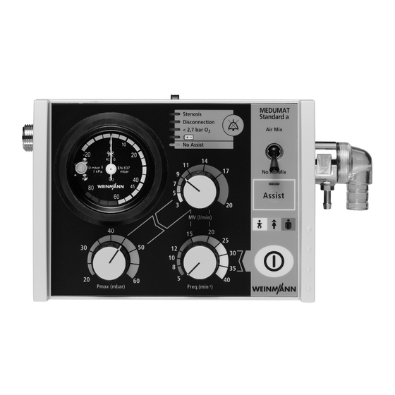
1. Overview 1.1 Device Control panel MEDUMAT Standard a 1 Ventilation pressure gauge 2 Alarm panel 3 Alarm acknowledgement MEDUMAT Stenosis Standard a Disconnection Air Mix < 2,7 bar O 4 Air Mix/No Air Mix switch No assist No Air Mix... - Page 5 MEDUMAT Standard a connections 11 Pressure gas connection 12 Catch for STATION MEDUMAT wall mounting 13 Connection for ventilation tube 14 Pressure gauge hose connection 15 Relief valve 16 Dust cover 17 Mixed air filter 12 Catch for STATION MEDUMAT...
- Page 6 MEDUMAT Standard a device combinations 18 Ventilation mask Disposable hose system 19 Ventilation hose 20 Pressure gauge hose 21 Filter 22 Hose casing 23 Patient valve 24 PEEP valve 25 Tube Overview...
-
Page 7: Symbols Used On The Ventilator
1.2 Symbols used on the ventilator Patient valve The symbol on the patient valve indicates that the lip and valve membranes in the expiration and spontaneous breathing arms must be changed im- mediately if they are crinkled, sticky or misshapen. Under no circumstances continue to use the patient valve for ventilation in this case, as malfunctions are likely (note “7.4 Check of patient valve“... - Page 8 MEDUMAT Standard a Inlet 2,7 - 6 bar O Tube system connection Maximum pressure ≤100mbar Safety check and servicing label Safety check label: (in Germany only) marks when the next safety check as per §6 of the German law relating to users of medical devices is required.
- Page 9 MEDUMAT Standard a device information plate Serial number of device Date of manufacture Direct voltage 3,6 V lithium battery Do not dispose of device in domestic waste CE symbol (confirms that the product conforms to the applicable European directives) Type BF application part Degree of protection –...
-
Page 10: Description Of Ventilator
2. Description of ventilator 2.1 Uses The MEDUMAT Standard a is an automatic (short- term) ventilator with the option of assisted ventila- tion. You can use MEDUMAT Standard a: • to revive patients at the site of the emergency •... -
Page 11: Owner/Operator And User Qualification
MEDUMAT Standard a cannot be used as a ven- tilator simultaneously with these modules.) 2.2 Owner/operator and user qualification As an owner/operator or user, you must be familiar with the operation of this medical device. Observe the legal requirements for operation and use (in Ger- many, the regulations governing owner/operators of medical devices apply in particular). - Page 12 in the patient valve ensures that the expiration gas can be exhaled through the expiration arm. Regardless of the ventilation mode selected, the pa- tient has the option of breathing spontaneously be- tween ventilation strokes via the patient valve. In this case, the patient draws air for breathing from the ambient air.
-
Page 13: Controlled Ventilation
2.4 Controlled ventilation Mandatory ventilation After being switched on, the MEDUMAT Standard a stroke: the device, not the is automatically in Controlled Ventilation mode. This patient, determines the administers mandatory ventilation strokes to the in- time of the next breathing tubated patient according to the ventilation values stroke. -
Page 14: Check Ventilation Curve
Respiration hose connection patient’s airways through the patient valve. Expiration tube It is designed so that spontaneous breathing is pos- sible, even if the MEDUMAT Standard a fails, regard- less of which ventilation mode you have selected. Connection Sponta- for pressure... -
Page 15: Modules
2.8 Modules Modules with additional functions can be attached to MEDUMAT Standard a. Please refer to the directions for use enclosed with the modules for exact details of how to fit and oper- ate these. It is essential to read these directions care- fully before using the modules. -
Page 16: Safety Instructions
Please comply with section “6. Hygienic prepara- tion“ on page 39 to prevent infection or bacte- rial contamination. • MEDUMAT Standard a should be used only by medically qualified personnel who have had training in ventilation techniques. Incorrect use can cause severe physical injury. - Page 17 • MEDUMAT Standard a should be used only for the purposes for which it is designed (note “2.1 Uses“ on page 10). • MEDUMAT Standard a is not designed for use under hyperbaric conditions (pressure chamber).
- Page 18 • MEDUMAT Standard a must never be used si- multaneously with a module as this would make it impossible to work to the selected parameters. Note •...
- Page 19 Accessories • Please protect the silicone and rubber compo- nents against UV radiation and prolonged expo- sure to direct sunlight, as this can make them brittle and friable. Safety instructions...
-
Page 20: Installation
4. Installation A permanent mounting is usually necessary only when MEDUMAT Standard a is installed as a fixture in rescue vehicles, helicopters or aircraft. In these cases either the STATION MEDUMAT or installation kits are available as accessories. If MEDUMAT Standard a is supplied complete with carrying platform, it is ready for use and requires no further installation. -
Page 21: Installation Kit For The Wall Mounting
Wait until the pres- sure gauge on the pressure reducer shows oxygen content before uncoupling the screw connection by hand. 2. First switch off MEDUMAT Standard a again. 3. Then loosen the screw connection to the cylinder. Installation... -
Page 22: Ventilation Hose
G 3/8 connecting nut. 4. Screw the other end of the pressure hose on to pressure gas connection on the MEDUMAT Standard a if this has not yet been done. 4.4 Ventilation hose 1. Slide the pressure gauge hose onto the connection. - Page 23 3. Plug the other end of the ventilation tube and the pressure measurement tube onto the patient valve. 4. If the patient is intubated, insert the patient valve into the tube, if a mask is being used for ventilation, insert the patient valve into the connector on the mask.
- Page 24 PEEP Valve If a PEEP valve is needed, this should be inserted into the expiration tube on the patient valve. Always follow the manufacturer’s directions for use. Bacteria filter If a bacteria filter is used, fit it between the device outlet port and the ventilation tube.
-
Page 25: Using The Ventilator
3. Select the desired settings for the ventilation (note “5.2 Selecting the ventilation settings“ on page 26). 4. Switch on the MEDUMAT Standard a with ON/ OFF switch. The ventilator will then run a self test lasting approx. 2 seconds. -
Page 26: Selecting The Ventilation Settings
5.2 Selecting the ventilation settings MEDUMAT The settings can be selected either before or after the Standard a must MEDUMAT Standard a is switched on. We recom- never be used mend selection before switching on to prevent simultaneously unnecessary waste of oxygen. - Page 27 Respiratory frequency 1. The respiratory frequency can be set with regulator knob. Minute volume 1. The minute volume can be set with regulator knob. Recommendation for breathing frequency and minute volume in the case of controlled ventilation: MV (l/min) Toddler Child Adult yellow...
-
Page 28: Select Ventilation Method
If the set level is reached, e.g. in cases where compli- ance is inadequate, MEDUMAT Standard a sets off a stenosis alarm (note “ Stenosis alarm“ on page 34). 5.3 Select ventilation method Ventilation in Controlled Ventilation mode The MEDUMAT Standard a is automatically in Controlled Ventilation mode when switched on. - Page 29 (note “5.10 Alarm signals“ on page 33). You end „Assisted Ventilation“ mode by pressing key Assist . The MEDUMAT Standard a then continues working in “Controlled Ventilation” mode. The LED Assist in key goes out.
-
Page 30: Performing Ventilation
1. Attach the patient valve to the connector of the tracheal tube. 2. Monitor the respiratory parameters during ventila- tion, e.g., with Weinmann’s CAPNOCOUNT mini WM 97144. This will indicate whether the tube is correctly positioned and ventilation is ade- quate. -
Page 31: Ventilation With Peep Valve
If lung compliance diminishes during ventilation in No Air Mix setting, the ventilator will react with an increase in ventilation pressure at constant vol- ume. For details of how MEDUMAT Standard a re- Air Mix acts in the setting, please refer to Section “11.5 O... -
Page 32: Ventilation With Hme Filter
5.7 Ventilation with HME filter A conventional heat and moisture exchange (HME) filter with standard 15/22 mm connectors can be fitted on the inspiration tube of the patient valve for hygienic purposes and to condition the inspired air. This will increase both inspiratory and expiratory resistance. -
Page 33: Terminating Ventilation
2. Close the valve of the oxygen cylinder. can cause corrosion. 3. Switch off MEDUMAT Standard a. ON/OFF switch must be kept pressed down for at least 2 seconds until the LEDs in the alarm panel light up. - Page 34 Actual ventilation pressure exceeds the level set with regulator knob max. ventilation pressure. Up to Serial No. 1799 MEDUMAT Standard a switches to expiration immedi- ately if the maximum ventilation pressure is exceeded. This does not affect the set frequency. Old appliances (up to serial no.1799) that have been given a new...
- Page 35 MEDUMAT Standard a has dropped to less than 2.7 bar. The reason is usually an almost empty oxygen cylinder. In this case MEDUMAT Standard a will no longer function correctly because the operating parameters will not lie within the permissible limits.
- Page 36 No Assist Alarm In “Assisted Ventilation” mode, patient fails to trig- ger within the time window in two consecutive phases. The LED in alarm field flashes and the acoustic alarm is triggered after a 1-minute delay. Cancelling acoustic alarm The acoustic alarm can be temporarily cancelled by pressing alarm acknowledgement: Stenosis: 30 Seconds...
-
Page 37: Calculation Of Oxygen Content/Remaining Operating Time
-content = 1000 l; MV = 11 l/min; 100% O This gives the following equation: 1000 l Real ventilation time(min) -------------------- - ¥ --------------- - 91 min 1 h 31 min 11 l/min 100% The real ventilation time is prolonged when MEDUMAT Standard a is switched to Mix. Using the ventilator... -
Page 38: Procedures
5.12 Alternative ventilation procedures If MEDUMAT Standard a ceases to function during a ventilation procedure, the following alternatives can be applied: Ventilation bags 1. Remove the patient valve from the tube or the mask. 2. Replace it with the ventilation bag, e.g. a Weinmann COMBIBAG WM 11000, and perform manual ventilation. -
Page 39: Hygienic Preparation
6.1 MEDUMAT Standard a MEDUMAT Standard a’s outer casing simply needs to be wiped with a dry or damp cloth. Never immerse MEDUMAT Standard a in disinfect- ant or other fluids. Just wipe over with disinfectant. -
Page 40: Patient Valve
6.2 Patient valve Always grasp the hoses by their ends. Otherwise you might damage or tear them. 1. Disconnect the patient valve from the hoses. 2. Dismantle the patient valve as shown in the ad- jacent diagram. It is neither necessary nor per- missible to remove the membrane in the spontaneous breathing nozzle for cleaning and disinfection. -
Page 41: Hose System
6.3 Hose system Caution! Only reusable hose system WM 22520 (scope of supply) is suitable for the hygienic preparation de- scribed here. Do subject disposable hose systems WM 28110 (2 m) and WM 28188 (3 m) available as accessories to hygiene preparation. Replace it with a new one. -
Page 42: Components And Accessories
2. Immerse the other end in the dilute disinfectant ® solution (for gigasept FF: 6% solution, residence time 15 minutes). 3. Draw the disinfectant solution through the pressure gauge tube into the syringe until the latter is full. Do not flush through the pressure gauge tube in the opposite direction! 4. -
Page 43: Fittings
4. Carry out a visual check of the masks and hoses and replace any damaged components. Silicone ventilation tubes, patient valves (see preced- ing section) and ventilation masks can also be autoclaved. This does apply to disposable hose systems WM 28110 (2 m) and WM 28188 (3 m). 6.5 Fittings In cases where external cleaning of fittings (e.g., pres- sure reducer, valve) becomes absolutely essential,... -
Page 44: Cleaning, Disinfecting And Sterilizing
6.6 Cleaning, disinfecting and sterilizing The hygienic preparation should be performed on MEDUMAT Standard a and the accessories used as described in the following table. Always follow the directions for use supplied with ® the disinfectant. We recommend gigasept FF (new) ®... -
Page 45: Functional Checks
7. Functional checks MEDUMAT Standard a must not be used if the func- tional checks reveal defects or deviations from the selected parameters. First try to correct the error with the help of the in- formation provided in section “8. Troubleshooting“... -
Page 46: Obligatory Checks
Note Check the test bag before each functional check. The balloon of the test bag must be un- damaged and firmly connected to the connec- tor. Have the test bag serviced at the same time as the device. 7.2 Obligatory checks Before each use: •... -
Page 47: Check For Leaks In The System
2. Wet all the screw and hose connections with the solution. Bubbles will form at the site of the leak. 3. Depressurise the system: To do this, first close the oxygen cylinder. Switch on MEDUMAT Standard a briefly until the pressure gauge on the O cylinder reads “ “. -
Page 48: Check Of Patient Valve
7.4 Check of patient valve Checking reusable hose system 1. Dismantle the patient valve. 2. Carry out a visual check of all the components for cracks or other physical damage. Crinkled, sticky or misshapen lip membranes must be changed immediately. They must never be used during ventilation as they can cause serious functional disturbances. -
Page 49: Checking The Minute Volume
5. Turn up the frequency to 40 min (right limit). 6. Count the number of inspiration phases over a period of one minute exactly. The number should lie between 38 and 42. 7. Switch MEDUMAT Standard a off again. Functional checks... - Page 50 Inspiration stroke = 4. Switch on MEDUMAT Standard a. The test bag MV/frequency = 8/8 = 1 must be completely inflated at the end of the in- spiration phase.
-
Page 51: Check Of Maximal Ventilation Pressure
3 L/min – 60 mbar – No Air mix 8. Switch on MEDUMAT Standard a and close the patient connection to the patient valve. A steno- sis alarm should be set off. 9. Switch MEDUMAT Standard a off again. Note Instead of the test bag you can also use a respiro- meter (see accessories) to check the breath volume. -
Page 52: Check Assisted Ventilation
MEDUMAT Standard a should set off the Stenosis alarm. 7.7 Check assisted ventilation 1. The MEDUMAT Standard a must be switched off and the oxygen cylinder must be open. 2. Plug the test bag with adapter of test set WM15382 onto the patient valve. - Page 53 No Assist LED goes out. This en- sures that the MEDUMAT Standard a recog- nizes trigger pulses. 8. Switch the MEDUMAT Standard a off again. Risk of injury if test bag removed incorrectly! If the test bag is removed incorrectly, the con- nector of the test bag may remain on the pa- tient’s hose system.
-
Page 54: Check Of Alarm Systems
The make the manometer nee- alarm should be set off. dle overswing considera- 6. Switch the MEDUMAT Standard a off again. bly. There are technical reasons for this and it does Interruption of breathing system not indicate any malfunc- (Disconnection) tion. - Page 55 MEDUMAT Standard a is switched on. The energy supply is in order if no alarm is set off when the valve on the oxygen cylinder is opened and MEDUMAT Standard a is switched on and starts to function correctly. Failure to trigger (No Assist) 1.
- Page 56 „No Assist“ must flash in alarm < 2,7 bar O field. The acoustic alarm sounds after a delay of No assist 1 minute if the fault has not been eliminated in the meantime. 5. Switch the MEDUMAT Standard a off again. Functional checks...
-
Page 57: Troubleshooting
8. Troubleshooting Defect Cause of defect Elimination MEDUMAT Standard a defective Arrange for repair MEDUMAT Standard a cannot be switched on Battery failure Replace both batteries (8.1, page 59) Obstruction of airways Remove obstruction. Tube incorrectly positioned Correct tube position. - Page 58 Kink in pressure gauge hose Wrongly selected ventilation Check ventilation parameters parameter MV too low MEDUMAT Standard a defective Arrange for repair Unusually high oxygen Leak in oxygen supply Seek and eliminate leak (7.3, page 47) consumption MEDUMAT Standard a...
-
Page 59: Batteries
: 3.6 V lithium battery for main power supply to MEDUMAT Standard a MEDUMAT Standard a is fitted with two batteries which should always be replaced simultaneously. Caution! A CR2430 button cell supplies auxiliary power to the Batteries and rechargeable electronics if the main batteries fail. -
Page 60: Cut-Out System
Battery replacement Important note! 1. Unscrew the back panel of MEDUMAT Standard a In order to prevent damage (6 cross-slotted screws). to the electronics, avoid all 2. Tilt the CR2430 button cell slightly to remove it. contact with the printed 3. -
Page 61: Adjustment Of Manometer
4. Replace the back panel and carry out a function- al check (see “7. Functional checks” on page 45). 8.3 Adjustment of manometer When MEDUMAT Standard a is switched off and the valve of the oxygen cylinder is closed, the manome- ter needle should read exactly “ “. - Page 62 3. Put in a new valve membrane. 4. Push the spontaneous breathing insert back into the patient valve. Expiration arm 1. Use pointed tweezers to pull the defective valve membrane out of the expiration arm. 2. Insert a new valve membrane. Note: This applies only to the reusable system.
-
Page 63: Servicing
9. Servicing 9.1 Intervals Have the cleaned and disinfected device serviced at regular intervals. Servicing, safety checks ([sicherhe- itstechnische Kontrollen or STKs] in accordance with §6 of the German law governing the owners/opera- tors of medical devices - only applies to Germany) and maintenance measures such as servicing and re- pairs may only be performed by the manufacturer or by specialists expressly so authorized by the manu-... -
Page 64: Sending In Device
WEINMANN Emergency at your expense. 9.3 Storage If you do not intend to use MEDUMAT Standard a for a long period, we recommend the following storage precautions: 1. Clean and disinfect the ventilator (note “6. -
Page 65: Disposal
2. Store MEDUMAT Standard a in a dry place. Important note! Remember that the ventilator still requires servic- ing at the stipulated intervals even when in stor- age, otherwise it cannot be used when removed from storage. Note With disposable hose systems WM 28110 (2 m) and WM 28188 (3 m), observe the storage tem- perature of -40 °C to 70 °C at a rel. -
Page 66: Supply Schedule
G 3/8 connection nut or connector socket to oxygen supply 5. Permanent fixing kit for MEDUMAT Standard a 15196 6. Permanent fixing kit for MEDUMAT Standard a plus 1 module 15198 7. Permanent fixing kit for a second module 15199 8. -
Page 67: Spare Parts
14. Device outlet port filter upgrade set 15780 15. Hose casing 8297 10.3 Spare parts You can order replacement parts separately if required. You can obtain a current list of replacement parts either on the Internet at www.weinmann-emergency.com or through your specialist dealer. Supply schedule... -
Page 68: Technical Data
11. Technical data 11.1 Device MEDUMAT Standard a MEDUMAT Standard a infinitely variable Dimensions 190x110x90 Ventilation frequency from 5 to 40 min LxBxH in mm inc. connections Weight incl. infinitely variable approx. 1.1 kg Minute volume (MV) accessories from 3 to 20 l/min Prod. - Page 69 MEDUMAT Standard a MEDUMAT Standard a Patient valve resist- Degree of ance (EN 794-3): protection against IP24 Inspiration <6 mbar at 60 l/min water Expiration <6 mbar at 60 l/min EN 60601-1 Elasticity of Standards applied EN 60601-1-2 Negligible breathing system...
-
Page 70: Patient's Hose System
22 mm external tapered connector – mask/endotracheal tube EN 5356-1 Patient valve 30 mm external tapered connector – expiration tube EN 5356-1 Ventilation tube connection WEINMANN Emergency-specific Standards applied EN 794-3 Patient valve resistance (as per EN 794-3): Inspiration <6 mbar at 60 l/min <6mbar... -
Page 71: Pneumatics
11.3 Pneumatics exp.-insp. amplifier valve input pressure 2.7 - 6 bar pressure regulator frequency regulator exhaust valve regulator valve manometer P/E converter injector unit patient valve non-return valve P/E converter relief valve A/D converter air mix valve evaluation electronics valve rocker air inlet The input pressure at p is max. -
Page 72: Resistance To Interference
Inspiration/Air Mix Valve rocker V6 is closed. This closes V7. O flows into injector unit V9 through V5 and sucks in air through V7. The air-oxygen mixture flows to the patient valve. Expiration/Air Mix or No Air Mix Another electrical impulse closes V2. Exhaust valve V4 opens and exhausts injector unit V9. - Page 73 10 mbar counter-pressure 15 mbar counter-pressure 30 mbar counter-pressure Minute volume (l/min) 11.6 Switching from Air Mix to No Air Mix The injector unit is switched off when switching Air Mix No Air Mix from . This increases minute vol- ume which can result in the set pressure limit being exceeded and a stenosis alarm (Stenosis) being trig-...
- Page 74 12. Warranty WEINMANN Emergency gives the customer a limited manufacturer warranty on new original WEINMANN Emergency products and any replacement part fitted by WEINMANN Emergency in accordance with the warranty conditions applicable to the product in question and in accordance with the warranty periods from date of purchase as listed below.
-
Page 76: Medical Technology Gmbh + Co. Kg
Manufacturer Center for Production, Logistics, Service WEINMANN Emergency WEINMANN Emergency Medical Technology GmbH + Co. KG Medical Technology GmbH + Co. KG Frohbösestraße 12 Siebenstücken 14 22525 Hamburg 24558 Henstedt-Ulzburg GERMANY GERMANY T: +49 40 88 18 96-120 E: customerservice@weinmann-emt.de...
Need help?
Do you have a question about the MEDUMAT Standard a and is the answer not in the manual?
Questions and answers