Bender ISOMETER isoCHA425 Manual
Insulation monitoring device for unearthed dc systems (it systems), dc 50 v up to 400 v, suitable for the charging of electric vehicles acc. to japanese charging standard chademo, software version: d612 v1.xx
Hide thumbs
Also See for ISOMETER isoCHA425:
- Manual (46 pages) ,
- Manual (46 pages) ,
- Quick start manual (13 pages)
Advertisement
Quick Links
Manual
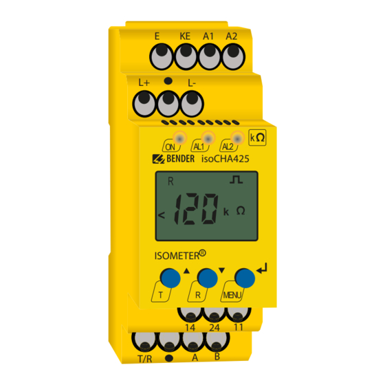
ISOMETER® isoCHA425
Insulation monitoring device for
unearthed DC systems (IT systems)
DC 50 V up to 400 V
Suitable for the charging of electric vehicles acc. to
Japanese charging standard CHAdeMO
Software version: D612 V1.xx
E
KE
A1 A2
L+
L-
k
AL1
AL2
ON
isoCHA425
k
<
ISOMETER
T
R
MENU
14
24
11
B
A
T/R
isoCHA425_D00352_01_M_XXEN/10.2019
Advertisement

Related Manuals for Bender ISOMETER isoCHA425


Summary of Contents for Bender ISOMETER isoCHA425
- Page 1 Manual ISOMETER® isoCHA425 A1 A2 isoCHA425 < ISOMETER Insulation monitoring device for unearthed DC systems (IT systems) MENU DC 50 V up to 400 V Suitable for the charging of electric vehicles acc. to Japanese charging standard CHAdeMO Software version: D612 V1.xx isoCHA425_D00352_01_M_XXEN/10.2019...
- Page 2 E-mail: info@bender.de Web: www.bender.de Customer service Service hotline: 0700-BenderHelp (telephone and fax) Carl-Benz-Straße 8 • 35305 Grünberg • Germany © Bender GmbH & Co. KG Tel.:+49 6401 807-760 All rights reserved. Fax:+49 6401 807-629 Reprinting only with permission of the publisher.
- Page 3 Table of Contents 1. Important information ..............5 3.2.11 Factory settings FAC ......... .11 3.2.12 External, combined test or reset button T/R .
- Page 4 7. Data access using the Modbus RTU protocol ......20 7.1 Reading out the Modbus register from the ISOMETER®....20 7.1.1 Command of the master to the ISOMETER® ..... 20 7.1.2 Answer of the ISOMETER®...
- Page 5 • Delivery of replacement devices in the event of faulty or incorrectly delivered erate injury or damage to property if not avoided. Bender devices CAUTION • Extended guarantee for Bender devices, which includes an in-house repair service or replacement devices at no extra cost Telephone: +49 6401 807-780** (technical issues)
- Page 6 • Batteries and accumulators are not part of household waste and must be disposed Sale and delivery conditions can be obtained from Bender in printed or electronic format. of in accordance with the regulations. 1.5 Inspection, transport and storage •...
- Page 7 2.3 Intended use Part of the device documentation in addition to this manual is the enclosed "Safety in- structions for Bender products". Only qualified personnel are permitted to carry out the work necessary to 2.2 Work activities on electrical installations install, commission and run a device or system.
- Page 8 DC+F Fault on system conductor DC- -> R = (200 % * R )/(100 % – R%) BMS interface (Bender measuring device interface) for data exchange with other DC-F • Bender components It is possible to assign the detected fault or the faulty conductor to an alarm relay via the menu.
- Page 9 Function Function 3.2.2 Function tests of relay in the charging station and the vehicle switches. The relays can be assigned to a device error with the parameter "Err" in the "out" menu in the alarm assignment. If the ISOMETER® is disconnected from the voltage source to be monitored single-pole Error codes during a function test of the charging station or vehicle relay, a false alarm can happen depending on the location of an existing insulation fault.
- Page 10 If the error occurs again after restarting the device or after restoring the factory settings, Delay on release please contact Bender Service. The delay on release t can be set uniformly for all messages in the "t" menu using the 3.2.8 Signalling assignment of the alarm relays K1/K2...
- Page 11 The ISOMETER® uses the serial hardware interface RS-485 with the following protocols: correct password being entered (0…999). • BMS The BMS protocol is an essential component of the Bender measuring device inter- 3.2.11 Factory settings FAC face (BMS bus protocol). Data transmission takes place with ASCII characters.
- Page 12 4. Installation, connection and commissioning Installation, connection and commissioning Dimension diagram, sketch for screw mounting, DIN rail mounting: Only qualified personnel are permitted to carry out the work necessary to in- stall, commission and run a device or system. Risk of electric shock! Touching live parts of the system carries the risk of: •...
- Page 13 Installation, connection and commissioning 4.2 Wiring diagram DC charging station acc. to CHAdeMO Test / Reset A1 A2 isoCHA425 < ISOMETER MENU off COM465IP RS-485 For details about the conductor cross sections required for wiring, refer to the technical data on page isoCHA425_D00352_01_M_XXEN/10.2019...
- Page 14 Installation, connection and commissioning Installation, connection and commissioning Wiring diagram legend: 4.3 Commissioning Terminal Connections 1. Check that the ISOMETER® is properly connected to the system to be monitored. Connection to the supply voltage U via fuse (line protection): 2. Connect the supply voltage U to the ISOMETER®.
- Page 15 5. Operation of the device Operation of the device The menu structure is illustrated schematically on the following pages. 5.1 Displays and buttons After pressing the "MENU" button for > 1.5 s, the first menu item "AL" appears. Use (Enter) buttons for navigation and settings. Device front/display Function green - on...
- Page 16 Operation of the device Operation of the device 5.2 Menu overview 5.3 "AL" menu 5.3.1 Response value setting Measurement display Standard display The two parameters that monitor the insulation resistance, "R1" and "R2", can be found in Menu selection Menu the response value menu "AL".
- Page 17 Operation of the device Operation of the device 5.4 Menu "out" 5.4.3 Fault memory configuration Display Description 5.4.1 Configuration of the relay operating mode Memory function for alarm messages (fault memory) Relay K1 Relay K2 Description FAC = Werkseinstellung; Ke = Kundeneinstellungen Display Display 5.4.4 Interface configuration...
- Page 18 L+ or L- with |R%| ≥ 30 %. In addition, it must be U ≥ 20 V in the DC system. Restore factory settings System leakage capacitance For Bender Service only μF μF ... 17 Resolution 1 FAC = Factory setting;...
- Page 19 6. Data access using the BMS protocol Data access using the BMS protocol The BMS protocol is an essential component of the Bender measuring device interface (BMS bus protocol). ASCII characters are used for the data transfer. BMS channel no.
- Page 20 7. Data access using the Modbus RTU protocol Data access using the Modbus RTU protocol Requests to the ISOMETER® can be made using the function code 0x03 (read multiple 7.2 Write Modbus register (parameter setting) registers) or the command 0x10 (write multiple registers). The ISOMETER® generates a Registers in the device can be modified with the Modbus command 0x10 (set multiple function-related answer and sends it back.
- Page 21 Data access using the Modbus RTU protocol Data access using the Modbus RTU protocol 7.3 Exception code If a request cannot be answered for whatever reason, the ISOMETER® will send a so-called exception code with which possible faults can be narrowed down. Exception code Description 0x01...
- Page 22 Modbus register assignment of the ISOMETER® Modbus register assignment of the ISOMETER® Depending on the device condition, the information in the registers is the measured val- Register Property Description Format Unit Value range ue without alarm; the measured value with alarm 1; the measured value with alarm 2; or only the device error.
- Page 23 Modbus register assignment of the ISOMETER® Modbus register assignment of the ISOMETER® Register Property Description Format Unit Value range Register Property Description Format Unit Value range 0 = BMS Factory settings for all 8003 UINT 16 0x6661 „fa“ 1 = 1.2 k parameters 2 = 2.4 k Factory setting only...
- Page 24 Modbus register assignment of the ISOMETER® Modbus register assignment of the ISOMETER® 8.1 Device-specific data type of the ISOMETER® 8.1.2.2 AT&T = Alarm type and test type (internal/external) Meaning 8.1.1 Device name The data format of the device name is specified below. Word 0x01 0x02...
- Page 25 Modbus register assignment of the ISOMETER® Modbus register assignment of the ISOMETER® 8.1.2.3 R&U = Range and unit 8.1.3 Alarm assignment of the relays Several alarms can be assigned to each relay. For the assignment of each relay, a 16-bit- Bedeutung register is used with the bits described below.
- Page 26 Modbus register assignment of the ISOMETER® Modbus register assignment of the ISOMETER® 8.2 Channel descriptions To convert parameter data, data type descriptions are required. Text representation is not necessary in this case. Measuring value description / Parameter Description of parameters Parameter Alarm message / Operating Note...
- Page 27 9. IsoData data string IsoData data string In IsoData mode, the ISOMETER® continuosly sends the whole data string with a cycle time of approximately 1 second. Communication with the ISOMETER® within this mode is not possible and no additional sender may be connected via the RS-485 bus cable. IsoData is activated in the menu "out", menu item "Adr"...
- Page 28 10. Technical data Technical data 10.1 Tabular presentation Measuring circuit Measuring voltage U ..............................±12 V ( )* = factory setting Measuring current I at R = 0 ..........................≤ 110 μA Internal resistance R Insulation coordination acc. to IEC 60664-1/IEC 60664-3 .............................≥...
- Page 29 Technical data Technical data Switching elements Degree of protection, terminals (DIN EN 60529) ......................IP20 Switching elements ...................... 2 x 1 contacts, common terminal 11 Enclosure material ............................polycarbonate DIN rail mounting acc. to ............................IEC 60715 Operating principle ..................N/C operation/N/O operation (N/C operation)* Screw fixing ..........................
- Page 30 INDEX Commissioning 14 Installation and connection 12 Configuration Interface/protocols Fault memory 17 BMS 11 Function 18 IsoData 11 Interface 17 Modbus RTU 11 Relay operating mode 17 IsoData Time 17 Data string 27 Connection 12 Malfunction 10 Data access Measuring times 10 BMS 19 Menu Modbus RTU 20...
- Page 31 Safety instructions 7 Self test 9 Automatic 10 Manual 10 Service 5 Signalling assignment alarm relays K1/K2 10 Start-up delay t 10 Support 5 Technical data 28 Training courses 6 Work activities on electrical installations 7 Workshops 6 isoCHA425_D00352_01_M_XXEN/10.2019...
- Page 32 Bender GmbH & Co. KG Customer service Postbox 1161 • 35301 Grünberg • Germany Service hotline: 0700-BenderHelp (Telephone and Fax) Londorfer Straße 65 • 35305 Grünberg • Germany Carl-Benz-Straße 8 • 35305 Grünberg • Germany Tel.: +49 6401 807-0 Tel.:...
Need help?
Do you have a question about the ISOMETER isoCHA425 and is the answer not in the manual?
Questions and answers