Table of Contents
Advertisement
Quick Links
Advertisement
Table of Contents

Related Manuals for Bender ISOMETER isoLR275


Summary of Contents for Bender ISOMETER isoLR275
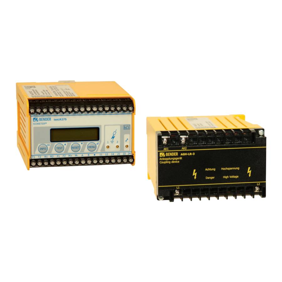
- Page 1 Manual ISOMETER® isoLR275 Coupling device AGH-LR Insulation monitoring device for unearthed IT AC, AC/DC and DC systems for electrical installations with a low level of resistance up to AC 793 V/DC 1100 V Software version: D369 V2.1 isoLR275_D00127_00_M_XXEN/07.2018...
- Page 2 P.O. Box 1161 • 35301 Grünberg • Germany Tel.: +49 6401 807-0 Fax: +49 6401 807-259 E-mail: info@bender.de Web: http://www.bender.de © Bender GmbH & Co. KG All rights reserved. Reprinting only with permission of the publisher. Subject to change! Photos: Bender archive and bendersystembau archive.
-
Page 3: Table Of Contents
Table of Contents 1. Safety instructions .................. 6 Intended use ......................6 1.1.1 Personnel ........................6 1.1.2 Hazards when handling the ISOMETER® isoLR275 ........6 1.1.3 Note ..........................7 Explanation of symbols and notes ..............8 Directions for installation ..................9 2. - Page 4 Table of Contents 5. Operation and configuration .............. 30 Display and operating elements ..............30 5.1.1 Display in standard mode ................... 31 5.1.2 Display in menu mode ..................32 5.1.3 Control buttons ...................... 32 Menu structure and menu mode ..............34 5.2.1 Navigation within the menu ................
- Page 5 Table of Contents 5.6.2 ISOnet function ...................... 49 5.6.3 ISO monitor ......................50 5.6.4 Diagram COM SETUP .................... 51 PASSWORD menu ....................52 5.7.1 Setting and activating the password ............. 52 5.7.2 PASSWORD diagram .................... 53 LANGUAGE Menu ....................54 5.8.1 Language setting ....................
-
Page 6: Safety Instructions
Monitoring the insulation resistance of IT systems Use which deviates from or is beyond the scope of these technical specifica- tions is considered non-compliant. The Bender companies shall not be liable for any losses or damage arising therefrom. Intended use also implies: Compliance with all information in this operating manual and ... -
Page 7: Note
Safety instructions Unauthorised persons must not have access to or contact with the ISOME- TER®. Information plates must always be clearly legible. Damaged or illegible signs must be replaced immediately. 1.1.3 Note Make sure that the operating voltage is correct! Prior to insulation and voltage tests, the ISOMETER®... -
Page 8: Explanation Of Symbols And Notes
Safety instructions 1.2 Explanation of symbols and notes To make it easier for you to understand and revisit certain sections of text and instructions in this manual, we have used symbols to identify important inst- ructions and information. The meaning of these symbols is explained below: This signal word indicates that there is a high risk of danger that will result in electrocution or serious injury if not avoided. -
Page 9: Directions For Installation
Safety instructions 1.3 Directions for installation Risk of property damage due to unprofessional installation! If more than one insulation monitoring device is connected CAUTION to aconductively connected system, the system can be da- maged. If several devices are connected, the device does not function and does not signal insulation faults. - Page 10 Safety instructions The device variant -3… is delivered with the following factory set- ting: Alarm 1/Alarm 2 = 4 kΩ/1 kΩ ISO SETUP: (response values) Operating mode K1/K2 = N/O operation ISO SETUP: (N.O.) Memory = off ISO SETUP: System leakage capacitance 150 µF ISO ADVANCED: Measurement method...
-
Page 11: Function
Memory with real-time clock to store alarm messages with date and time stamp BMS interface (Bender Measuring Device Interface) for communication with other Bender devices (RS-485 galvanically isolated) Internal disconnection of the ISOMETER® from the IT system to be ... -
Page 12: Device Features Agh-Lr
Function 2.2 Device features AGH-LR Coupling device required for ISOMETER® isoLR275, each AGH-LR is specially adapted to the corresponding isoLR275 Nominal voltage range AC 0…793 V and DC 0…1,100 V DIN rail mounting 2.3 Product description The isoLR275 ISOMETER®... -
Page 13: Description Of Function
25 % and at least 1 kW above the actual response va- lue. The fault memory behaviour can also be set in the "ISO SETUP“ menu, by selecting the submenu Memory: on/off. measurement method (Adaptive Measuring Pulse), a measurement method developed by Bender (European Patent: EP 0 654 673 B1). isoLR275_D00127_00_M_XXEN/07.2018... -
Page 14: Measurement Profiles
Function 2.4.1 Measurement profiles The measuring circuit of the isoLR275 can be adjusted to different require- ments in the ISO ADVANCED/MEASURE menu: = Suitable for pure AC systems = Suitable for converters with frequencies > 10 Hz AMP2 = Suitable for converters with frequencies < 10 Hz AMP3 = Suitable for converters with frequencies <... -
Page 15: Self Test
Function 2.4.2 Self test A self test can be started automatically or manually by means of the test but- ton. In order to guarantee high functional reliability, the ISOMETER® provides comprehensive self test functions. After switching the device to the supply voltage, all internal measuring functions, the components of the process con- trol such as data and parameter memory as well as system and earth connec- tions are checked using the self test functions. -
Page 16: Current Output For External Measuring Instrument
1. Press the "TEST" button error 2. Switch the supply voltage off and on 3. Please contact Bender If, for functional reasons, the supply voltage cannot be switched on or off, a reset of the sequence control system can be carried out by pressing the buttons "ESC", "RESET" and "MENU“... -
Page 17: Real-Time Clock
Function 2.4.4 Real-time clock The real-time clock serves as a time base for the memory and self test func- tions. First, the correct time and date must be set in the "ISO ADVANCED“ me- nu. If time and date are not set, a "C“ (clock) is flashing in the standard display. In the event of a supply voltage failure, time and date will be stored for at least 30 days. -
Page 18: Function Input F1/F2 For Connection Or Disconnection Of It Systems Being Monitored
Function 2.4.6 Function input F1/F2 for connection or disconnection of IT systems being monitored The ISOMETER® can be disconnected from the IT system and set to STANDBY mode with the function input F1/F2. If the input F1/F2 is bridged, the connec- tions to the coupling device AK1/AK2 are switched off via internal coupling re- lays, the measuring function is stopped and the message "STANDBY"... - Page 19 Function BMS bus RS-485) Addr. Addr. isoLR275 isoLR275 AGH-LR AGH-LR Addr. Addr. isoLR275 isoLR275 AGH-LR AGH-LR isoLR275_D00127_00_M_XXEN/07.2018...
-
Page 20: Isonet Function (Com Setup)
Function 2.4.7 ISOnet function (COM SETUP) To activate this function, select "ISOnet=ON“ in the COM SETUP menu. This function is a type of scanning function. The BMS master with activated ISOnet function controls the ISOnet slave devices via the BMS bus. When the master ISOMETER®... - Page 21 Function BMS bus RS-485) Addr. Addr. isoLR275 isoLR275 AGH-LR AGH-LR IT system 2 IT system 1 IT system 3 IT system 4 Addr. Addr. isoLR275 isoLR275 AGH-LR AGH-LR isoLR275_D00127_00_M_XXEN/07.2018...
-
Page 22: Commissioning Flow Chart (In Three Parts)
3. Commissioning flow chart (in three parts) Due to limitations of space, the three-part flow chart begins on the next page. isoLR275_D00127_00_M_XXEN/07.2018... - Page 23 Commissioning of the ISOMETER® (1) Is the system to be monitored an isoLR is not suitable for this unearthed system (IT system)? application( contact Bender) Is the maximum nominal voltage isoLR is not suitable for this U n ≤ AC 793 V application( contact Bender) and is U n ≤...
- Page 24 Commissioning flow chart (in three parts) Commissioning of the ISOMETER® (2) Connect the supply voltage U S The ISOMETER carries out a self test. The display indicates Connect the voltage U n of the the insulation value after finishing IT system to be monitored the measurement Set the clock Shall the basic setting...
- Page 25 Commissioning flow chart (in three parts) Commissioning of the ISOMETER® (3) In order to check the proper connection, a functional test using a suitable resistance is to be carried out. Size of the resistance: 50% of the preset response value Alarm 2. Check the connecting leads ! Do both alarm LEDs light up? Is voltage Un applied to the...
-
Page 26: Installation And Connection
4. Installation and connection 4.1 Mounting of the isoLR275 Install the isoLR275 and the AGH-LR with a distance of at least 30 mm to all adjacent devices to ensure compliance with prescribed temperature limits. The cable lengths between AGH-LR and isoLR275 must not exceed 0.5 m. - Page 27 Installation and connection An external test button or an external reset button may only be connected to one ISOMETER®. A parallel connection of several test and reset inputs for collective ISOMETER® testing is not allowed. For UL applications: Use 60 °C/75 °C copper conductors only! Tightening torque: isoPV: 0.6 Nm…0.8 Nm, AGH-PV: 0.5 Nm isoLR275_D00127_00_M_XXEN/07.2018...
- Page 28 Installation and connection 3 AC system AC system 3/N AC system DC system L1 L2 AGH-LR A1/+ A2/- isoLR275 T1 T2 R1 R2 F1 F2 M+ M- A B 11 12 14 21 22 24 isoLR275_D00127_00_M_XXEN/07.2018...
- Page 29 Installation and connection Legend wiring diagram: Supply voltage U (see nameplate) via 6 A fuse; For UL and CSA applications, it is mandatory to use 5 A fuses. Connection to the 3 AC system to be monitored: 2, 3 Connect the terminals L1, L2 to neutral conductor N or terminals L1, L2 to conductor L1, L2.
-
Page 30: Operation And Configuration
5. Operation and configuration 5.1 Display and operating elements LR275 "INFO" button: to query standard information/ "ESC" button: back (menu function), to confirm parameter change "TEST" button: to call up the self test/ Arrow up button: parameter change, to move up in the menu "RESET"... -
Page 31: Display In Standard Mode
Operation and configuration 5.1.1 Display in standard mode I n s u l a t i o n F a u l t Ω R s = 0 1 1 k Indication of the insulation resistance in kΩ Additional information about the insulation resistance: „+“... -
Page 32: Display In Menu Mode
Setup status (for details about the setup status refer to the status table on page 71) COM-Setup (own bus address) Please have the details above on hand if you have a problem and if you con- tact Bender for technical questions. isoLR275_D00127_00_M_XXEN/07.2018... - Page 33 Operation and configuration Press the "TEST" button to start the self test of the ISOMETER®. Press the "RESET" button to reset insulati- on fault alarms stored in the ISOMETER®. The memory function is only available af- ter activating the fault memory in the ISO SETUP menu or after bridging the terminals R1/R2.
-
Page 34: Menu Structure And Menu Mode
Operation and configuration "ESC" button: To return from a sub menu to the previous menu. If the menu is not exited, the device automatically returns to the standard mode again after approximately five minutes. For the sake of clarity, the following symbols are used in the menu diagrams for the representation of ENTER, UP/DOWN and "ESC": 5.2 Menu structure and menu mode To switch to the menu mode... -
Page 35: Changing From The Menu Mode To The Standard Mode
Operation and configuration Changing the parameters usually has an immediate effect on the measuring and alarm functions. The changed parameter is stored in a non-volatile me- mory by pressing the Enter or "ESC" button after returning to the sub menu (flashing cursor in column 1). -
Page 36: Diagram Menu Structure
Operation and configuration 5.2.4 Diagram menu structure *** IT-SYSTEM *** MENU R >1.0 MΩ 1. EXIT 2. HISTORY INFO 3. ISO SETUP 4. ISO ADVANCED 5. COM SETUP 6. PASSWORD 7. LANGUAGE 8. SERVICE HISTORY INFO ISO SETUP ISO ADVANCED COM SETUP PASSWORD LANGUAGE... -
Page 37: Menu History Info
Operation and configuration 5.3 Menu HISTORY INFO 99 events with date and time stamp can be stored in the memory database. The database is designed as a ring memory, i.e. the eldest entry is overwritten. Data is written into a non-volatile memory and therefore is protected against voltage failure. -
Page 38: Diagram History Info
Operation and configuration 5.3.1 Diagram HISTORY INFO isoLR275_D00127_00_M_XXEN/07.2018... -
Page 39: Menu Iso Setup: Setting Of The Basic Isometer® Functions
Operation and configuration 5.4 Menu ISO SETUP: Setting of the basic ISOMETER® functions This menu is used to set the alarm functions Alarm1 and Alarm2 (prewarning and alarm), the operating principle of the alarm relays K1 and K2 (N.O = N/O operation, N.C = N/C operation), the fault storage behaviour and a selection of two current output ranges. - Page 40 Operation and configuration K2: N.C Test = N/C operation contacts 21-22-24, with relay test (the alarm relay is energised during normal operation) K2: N.O Test = N/O operation contacts 21-22-24, with relay test (the alarm relay is deenergised during normal operation) K2 : N.C = N/C operation contacts 21-22-24, without relay test (the alarm relay is energised during normal operation)
- Page 41 Operation and configuration ISO SETUP diagram isoLR275_D00127_00_M_XXEN/07.2018...
-
Page 42: Memory Setting (On/Off)
Operation and configuration During the automatic self test, the alarm relays are not switched over. In case of a malfunction of the ISOMETER®, the relay K2 will auto- matically be activated as a device error relay. 5.4.3 Memory setting (on/off) Memory: on = Fault memory is activated The device must be reset with the reset button after... - Page 43 Operation and configuration The function of the current output is dependent on the selected R Function 0…20 mA: = insulation fault, I = current in mA Function 4…20 mA: = insulation fault, I = current in mA Refer to the associated characteristic curves on page 69. For UL applications: The analogue output as such is not a “safe alarm”...
-
Page 44: Menu Iso Advanced: Setting Of The Extended Functions
Operation and configuration 5.5 Menu ISO ADVANCED: Setting of the extended functions 5.5.1 External coupling device (AGH: LR) Use the isoLR275 only in conjunction with the AGH-LR coupling device. The menu setting AGH:PV is pre-defined. The current software version does not allow other settings. - Page 45 Operation and configuration Setting the parameter e max 150μF 500μF Response time Response time Profile (acc. to IEC 61557-8) Description setting = 1kΩ = 1kΩ = 1μF = 200μF Standard mea- DC measurement surement method method permissible using a DC <...
- Page 46 Operation and configuration Setting the parameter e max 150μF 500μF Optimised measu- rement method using the pulse measurement < 30s < 50s AMP2 method for AC/ DC systems at system frequen- cies < 10 Hz Optimised measu- rement method for AC/DC sys- <...
-
Page 47: Setting The Repetition Time For The Automatic Self Test (Autotest: 24H)
Operation and configuration 5.5.4 Setting the repetition time for the automatic self test (Autotest: 24h) The time for the repetition of automatic self tests can either be set to 1 hour or to 24 hours or can be deactivated. Factory setting = 24 h 5.5.5 Setting the real-time clock (Clock) The time setting is the time base for the memory and the automatic self test. -
Page 48: Diagram Iso Advanced
Operation and configuration 5.5.8 Diagram ISO ADVANCED *** IT-SYSTEM *** R >1.0 MΩ 1. EXIT 2. HISTORY INFO 3. ISO SETUP 4. ISO ADVANCED 5. COM SETUP 6. PASSWORD 7. LANGUAGE 8. SERVICE 1. Exit 2. AGH: PV 3. Ce max : 150μF 4. -
Page 49: Menu Com Setup: Setting The Bms Interface
Operation and configuration 5.6 Menu COM SETUP: Setting the BMS interface 5.6.1 Bus address "Addr:" This menu is used to set the BMS bus address for isoLR275. Take care that the bus address is not assigned twice. The device is factory set to address 3 and hence operates as a slave. If several isoLR275s are operated on one BMS bus, the address of other ISOMETER®s must be assigned one after the other, since only one device may have the master function. -
Page 50: Iso Monitor
Operation and configuration 5.6.3 ISO monitor This function allows to query the currently measured value as well as the mes- sages of all bus-capable ISOMETER®s existing in the BMS network. After selec- ting the bus address, the entire information stored by the selected device is indicated on the display. -
Page 51: Diagram Com Setup
Operation and configuration 5.6.4 Diagram COM SETUP isoLR275_D00127_00_M_XXEN/07.2018... -
Page 52: Password Menu
Operation and configuration 5.7 PASSWORD menu 5.7.1 Setting and activating the password This menu can be used to activate a "Password" query. This protects the ISOMETER® against unauthorised settings and modifications. Set the desired password using the Up/Down buttons (menu item "2. Pass- word: xxx") password: and confirm the setting with the Enter button. -
Page 53: Password Diagram
Operation and configuration 5.7.2 PASSWORD diagram isoLR275_D00127_00_M_XXEN/07.2018... -
Page 54: Language Menu
Operation and configuration 5.8 LANGUAGE Menu 5.8.1 Language setting The menu item "Language" allows fault messages of the ISOMETER® to be set to different languages. There is a choice of German and English. The device menu is not influenced by the language selection. isoLR275_D00127_00_M_XXEN/07.2018... -
Page 55: Language Diagram
Language diagram 5.9 SERVICE menu This menu item is intended for the Bender service personnel and protected by a password against erroneous settings. It is intended for fast fault clearance by qualified experts in the event of a device error. -
Page 56: Serial Interface
6. Serial interface 6.1 RS-485 interface with BMS protocol The RS-485 interface electrically isolated from the device electronics and the current output serves as a physical transmission medium for the BMS proto- col. If several isoLR275 or other bus-capable devices are interconnected in a network via the BMS bus, the BMS bus must be terminated at both ends with a 120 Ω... -
Page 57: Topology Rs-485 Network
(e.g. J-Y(St)Y 2x0.6), shield connected to earth (PE) on one end. Connection to the terminals A and B. The number of bus nodes is restricted to 32 devices. When more devices are to be connected, Bender recommends to use a DI1 repeater. isoLR275_D00127_00_M_XXEN/07.2018... -
Page 58: Bms Protocol
Serial interface 6.3 BMS protocol This protocol is an essential part of the Bender measuring device interface (BMS bus protocol). Data transmission generally makes use of ASCII characters. Interface data are: Baud rate: 9600 baud Transmission: 1 start bit, 7 data bits, 1 parity bit, 1 stop bit ... -
Page 59: Bms Master
Serial interface 6.3.1 BMS master A master can query all warning and operational messages from a slave. If the bus address 1 has been selected for one isoLR275, the device automati- cally represents the master, that means that all addresses between 1 and 150 are cyclically scanned for alarm and operational messages via the BMS bus. -
Page 60: Bms Slave
Serial interface 6.3.2 BMS slave All isoLR275 devices are factory-set to slave mode (address 3). In a BMS net- work, one address must be selected from the address range 2...30 for each sla- ve. There may be no gaps of more than five subsequent addresses, so that all slaves can be scanned by the master. -
Page 61: Commissioning Of An Rs-485 Network With Bms Protocol
Serial interface The following table gives an overview about essential alarm messages and the assignment of the messages indicated on the display or alarm indicator and test combinations, e.g. MK800. Alarm Channel Note Insulation Fault Insulation resistance < setting value Alarm 1 Isolation Fehler Insulation resistance <... - Page 62 Serial interface BMS bus address ranges (internal bus) Addresses* Device Note There is no device with address 0 ! Informa- tion sent to address 0 applies to all devices connected to the interfaces (broadcast) 1…30 IRDH275B/ Insulation monitoring devices 375B/575; isoPV isoLR275 1…30 FTC4…...
-
Page 63: Technical Data Isolr275 With Agh-Lr
7. Technical data isoLR275 with AGH-LR 7.1 isoLR275 data in tabular form The values marked with** are absolute values. ()* = factory setting Insulation coordination acc. to IEC 60664-1/IEC 60664-3 Rated voltage for isoLR275-3 ...........................AC 250 V Rated impulse voltage/pollution degree......................6 kV/III Protective separation (reinforced insulation) between.................... - Page 64 Technical data isoLR275 with AGH-LR For UL applications: Nominal system voltage U .......................... via AGH-LR isoLR275-335: Supply voltage U (also see nameplate) ....................AC 88…250 V Frequency range U ........................... 42…460 Hz Power consumption AC ..........................≤ 21,5 VA Supply voltage U (also see nameplate) ....................
- Page 65 Technical data isoLR275 with AGH-LR Outputs/Inputs "TEST"-/"RESET" button........................internal/external Cable length "TEST"/"RESET" button, external ....................≤ 10 m Current output (load) ......................0/4…20 mA (≤ 500 Ω) Accuracy current output, related to the value indicated (1 kΩ…100 kΩ) .................. ±15 %, ±1 kΩ Serial interface Interface/protocol ............................
- Page 66 Technical data isoLR275 with AGH-LR Classification of mechanical conditions acc. to IEC 60721: Stationary use (IEC 60721-3-3) ............................for screw fixing with accessories B990056 ......................3M7 for DIN rail mounting .............................. 3M4 Transport (IEC 60721-3-2) ............................. 2M2 Long-term storage (IEC 60721-3-1) ........................1M3 Connection Connection ............................
-
Page 67: Agh-Lr Data In Tabular Form
Technical data isoLR275 with AGH-LR 7.2 AGH-LR data in tabular form Insulation coordination acc. to IEC 60664-1 Rated insulation voltage........................... AC 800 V Rated impulse voltage/pollution degree......................8 kV/3 Voltage ranges Nominal system voltage U ................AC, 3(N)AC 0…793 V, DC 0…1,100 V Nominal frequency f .......................... -
Page 68: Standards, Approvals And Certifications
Technical data isoLR275 with AGH-LR Type of enclosure ........................X200, free from halogen DIN rail mounting........................DIN EN 60715/IEC 60715 Screw mounting..............................2 x M4 Flammability class ............................UL94 V-0 Weight ................................< 230 g 7.3 Standards, approvals and certifications The ISOMETER® was designed in compliance with the following standards: - DIN EN 61557-8 (VDE 0413-8) - IEC 61557-8 - IEC 61326-2-4... -
Page 69: Characteristic Curves
Technical data isoLR275 with AGH-LR 7.4 Characteristic curves Current output 0…20 mA [k:] 1000,00 Rsk=28kOhm Rsk=120kOhm 100,00 10,00 1,00 10,0 15,0 20,0 25,0 I[mA] = Insulation fault in kΩ = Centre scale in kΩ I = Current output in mA isoLR275_D00127_00_M_XXEN/07.2018... - Page 70 Technical data isoLR275 with AGH-LR Current output 4…20 mA [k:] 1000,00 Rsk=28kOhm Rsk=120kOhm 100,00 10,00 1,00 10,0 15,0 20,0 25,0 I[mA] = Insulation fault in kΩ = Centre scale in kΩ I = Current output in mA isoLR275_D00127_00_M_XXEN/07.2018...
- Page 71 Technical data isoLR275 with AGH-LR Status number isoLR275_D00127_00_M_XXEN/07.2018...
- Page 72 Technical data isoLR275 with AGH-LR Dimension diagram enclosure isoLR275 All dimensions in mm DIN rail mounting according to DIN EN 60715/IEC 60715 Screw mounting by means of a plug-in trapezoidal support Order-No.: B990056 isoLR275_D00127_00_M_XXEN/07.2018...
- Page 73 Technical data isoLR275 with AGH-LR Dimension diagram enclosure AGH-LR All dimensions in mm Illustration with terminal covers isoLR275_D00127_00_M_XXEN/07.2018...
-
Page 74: Ordering Information
Technical data isoLR275 with AGH-LR 7.5 Ordering information Nominal voltage Supply Type Art. No. voltage AC 19.2…55 V B 9106 5702W 3(N)AC 0…793 V isoLR275-327 42…460 Hz DC 0…1100 V + AGH-LR-3 DC 19.2…72 V consisting of: B 9106 5700W isoLR275-327 B 9803 9022W AGH-LR... -
Page 75: Label For Modified Versions
Technical data isoLR275 with AGH-LR 7.6 Label for modified versions There will only be a label in this field, if the ISOMETER® is different from the standard version. isoLR275_D00127_00_M_XXEN/07.2018... -
Page 76: Index
- LED 1 30 Assigning bus address for isoLR275 49 Flashing point 60 Automatic self test, setting 47 Function input F1/F2 18 Bender measuring device interface (BMS) 58 INFO button 30 BMS addresses 62 ISO monitor 50 BMS master 59... - Page 77 INDEX Real-time clock 17 RESET button 30 RS-485 interface 56 RS-485 network - Correct arrangement 57 - Wrong arrangement 57 Setting and activating password 52 Setting operating principle alarm relays 39 Setting response values Alarm1/Alarm2 39 Standards 68 Status number 71 System leakage capacitance, max.
- Page 80 Bender GmbH & Co. KG Londorfer Str. 65 • 35305 Grünberg • Germany P.O. Box 1161 • 35301 Grünberg • Germany Tel.: +49 6401 807-0 Fax: +49 6401 807-259 E-mail: info@bender-de.com Web: http://www.bender-de.com...
Need help?
Do you have a question about the ISOMETER isoLR275 and is the answer not in the manual?
Questions and answers