
Related Manuals for YILMAZ SC 550P


Summary of Contents for YILMAZ SC 550P
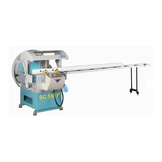
- Page 1 SC 550P TEK KAFA KESİM MAKİNESİ LARGE CAPACITY MITRE SAW УСОРЕЗНАЯ ПОРТАТИВНАЯ ПИЛА С РУЧНОЙ ПОДАЧЕЙ USER MANUAL – KULLANICI EL KİTABI - РУКОВОДСТВО ПО ЭКСПЛУАТАЦИИ...
- Page 2 GARANTİ BELGESİ İMALATÇI FİRMA YILMAZ MAKİNE SANAYİ VE TİCARET A.Ş ADRES TAŞDELEN MH. ATABEY CD. No 9 34788 ÇEKMEKÖY İSTANBUL-TÜRKİYE TELEFON 0216.312.28.28 PBX TELEFAX 0216.484.42.88 İMZA-KAŞE ÜRÜNÜN CİNSİ TEK KAFA KESİM MAKİNESİ MARKASI YILMAZ MODEL KODU SC 550P BANDROL/SERİ NO TESLİM TARİHİ...
- Page 3 TECHNICAL FEATURES - ТЕХНИЧЕСКИЕ ОСОБЕННОСТИ 2400 W = 97 2.2 kW 50 Hz 2.2 kW 50 Hz D = 550 mm SC 550P D/dak. 6/8 Bar Lt. / dak. L = 150 400 V AC 3 P PE 230 V AC 3P PE...
- Page 4 BOYUTLAR – DIMENSIONS – РАЗМЕРЫ RESİM-FIGURE-РИСУНОК 1...
- Page 5 KESME DİYAGRAMI – CUTTING DIAGRAM - ДИАГРАММА РЕЗКИ...
- Page 6 PARÇA LİSTESİ - PART LIST - ПЕРЕЧЕНЬ ДЕТАЛЕЙ RESİM-FIGURE-РИСУНОК 3 RESİM-FIGURE-РИСУНОК 2 RESİM-FIGURE-РИСУНОК 5 RESİM-FIGURE-РИСУНОК 4...
- Page 7 RESİM-FIGURE-РИСУНОК 7 RESİM-FIGURE-РИСУНОК 6 RESİM-FIGURE-РИСУНОК 9 RESİM-FIGURE-РИСУНОК 8...
- Page 8 RESİM-FIGURE-РИСУНОК 10 RESİM-FIGURE-РИСУНОК 12 RESİM-FIGURE-РИСУНОК 11...
- Page 9 STOK KODU ADET STOK KODU ADET STOCK CODE STOCK CODE номер номер ПОРЯДОК КОД КОЛИЧЕСТВО ПОРЯДОК КОД КОЛИЧЕСТВО 1SA010000-0061 3UA680030-0005 1SC170000-0014 3UA040030-0020 1SA030000-0076 2TU012510-0346 4UN300030-0001 3UA670030-0005 3UA680030-0052 1EL070001-0002 1PL010000-0069 2TU011110-1061 1SA030000-0078 1SK010000-0046 3UA110030-0020 2TU011110-0982 1EL010000-0046 1SC011000-0017 1SA020000-0049 2TU011110-0986 3UA670030-0320 2TU011441-0482 3UA060030-0004 2TU012610-0044 3UA680030-0006...
- Page 10 YEDEK PARÇA LİSTESİ / SPARE PART LIST / СПИСОК ЗАПАСНЫХ ЧАСТЕЙ PARÇA NO RESİM PARÇA ADI – PART NAME STOK KODU / CODE PART NO PICTURE ПОРЯДОК КОД НАИМЕНОВАНИЕ ДЕТАЛИ НОМЕР РИСУНОК MENGENE PİSTONU BAĞLANTISI 2TU012610-0044 PISTON CLAMP CONNECTION PNÖMATİK MENGENE 3UA060030-0004 PNEUMATIC CLAMP 1/8-6 REKOR...
- Page 11 YEDEK PARÇA LİSTESİ / SPARE PART LIST / СПИСОК ЗАПАСНЫХ ЧАСТЕЙ PARÇA NO RESİM PARÇA ADI – PART NAME STOK KODU / CODE PART NO PICTURE ПОРЯДОК КОД НАИМЕНОВАНИЕ ДЕТАЛИ НОМЕР РИСУНОК M8x32 PİPO 3UA040030-0007 M8x32 HANDLE M12*60 PİPO 3UA040030-0001 M12*60 HANDLE M10*40 PİPO 3UA040030-0020...
- Page 12 YEDEK PARÇA LİSTESİ / SPARE PART LIST / СПИСОК ЗАПАСНЫХ ЧАСТЕЙ PARÇA NO STOK KODU / CODE PARÇA ADI – PART NAME - PART NO RESİM ПОРЯДОК КОД MOTOR KAYIŞI 1SR070000-0005 MOTOR BELT SPRAYER SU PÜSKÜRTME VALF 1PN010000-0012 WATER SPRAY VALVE TESTERE KANAL LAMASI 2TU011441-0014 SAW CHUTE PLATE...
- Page 13 YEDEK PARÇA LİSTESİ / SPARE PART LIST / СПИСОК ЗАПАСНЫХ ЧАСТЕЙ PARÇA NO STOK KODU / CODE PARÇA ADI – PART NAME - PART NO RESİM ПОРЯДОК КОД 1EL070001-0002 MOTOR 400V-415V (3P 50 Hz) MOTOR...
-
Page 14: Table Of Contents
ENGLISH CONTENTS 1. General information 1.1. Introduction 1.2. Service Information 2. Safety 2.1. Safety Symbols and Their Meanings 2.2. Accidents Prevention 2.3. General Safety Information 3. Machine’s Description 4. Transport of the Machine 5. Installation of the Machine 5.1. Preparation 5.2. -
Page 15: General Information
The technical drawings and details contained in this manual constitute a guide for the operator. 1.2. Service Information In case of any technical problem please contact your nearest YILMAZ dealer, or YILMAZ head office through the above mentioned phone, fax or e-mail address. - Page 16 AUTHORIZED TECHNICAL SERVICE CENTER ADDRESS TAŞDELEN MH. ATABEY CD. No 9 34788 ÇEKMEKÖY – İSTANBUL / TÜRKİYE 0216 312 28 28 Pbx. 0216 484 42 88 E-mail service@yilmazmachine.com.tr www.yilmazmachine.com.tr For minimize the documantation, It is wery necessary to mention below details at the agreements signed with suppliers and dealers of the purchased machines ...
-
Page 17: Safety
2. SAFETY 2.1. Safety Symbols and Their Meanings Ensure safe working position, always keep your Read the user guide balance. Wear ear protectors Elektrical excitation Wear safety goggles Don’t place your hands between parts in motion.. If the power cable should be damaged during operation, don't touch and unplug it. -
Page 18: Accidents Prevention
2.1. Accidents Prevention 2.2.1 Our machines are manufactured in accordance with CE safety directives, which cover national and international safety directives. 2.2.2 It is the task of the employer to warn his staff against accident risks, to train them on prevention of accidents, to provide for necessary safety equipment and devices for the operator’s safety. - Page 19 2.3.4 Use correct illumination for the safety of the operator. ( ISO 8995-89 Standard The lighting of indoor work system) 2.3.5 Don’t use any materials other than those recommended by the manufacturer for cutting operations on the machine. 2.3.6 Ensure that the work piece is clamped appropriately by the machine's clamp or vice 2.3.7 Ensure safe working position, always keep your balance.
-
Page 20: Machine's Description
3. MACHINE’S DESCRIPTION Cutting machines with 550 mm diameter circular saw for cutting. PVC and Aluminum profiles in right angle or various angles in required lengths. The feature to be able to cut in the cutting unit in the internal and external angles, ... -
Page 21: Installation Of The Machine
4.3. Do not lift the machine before you are sure that the bearing knives of the equipments such as fork-lift come under the machine when transferring the machine. 4.4. Movable parts on the machine should be fixed before carrying out the transport. 4.5. -
Page 22: Connecting To Power Source
5.2 Connecting to the Power Source 5.2.1 The Electrical connection must be made by a licensed electrician 5.2.2 The power outlet socket on the machine should be available. 5.2.3 Plug the machine to a grounded socket. 5.2.4 Main voltage of the machine is optional as 230 V 50 Hz or 400 V 50 Hz. 5.2.5 Maket he electrical socket connections after positioning the MAIN SWITCHI on the machine to 0. -
Page 23: Operation
7.1.2 Clean all surfaces of the machine from chip and foreign particles. Use eye glasses for protection. 7.1.3 SC 550P cutting machines cut the products made of aluminium, wood and hard plastic materials that are not ferroalloy. The operator adjusts the saw cutting progress according to the type and size of the material to be cut. - Page 24 7.1.7 Adjust the reducer speed adjustment screw (See Figure-11) by rotating in the direction of clockwise until providing the desired progress if the saw group cutting progress is fast. Make the opposite of the above action if the saw group cutting progress is slow. 7.1.8 According to the type and shape of the material to be cut it can be adjusted by controlling the clamp speed.
-
Page 25: Operation
7.2 Operation When the machine is opened from the Main Switch (FIGURE 3 NO 9) or the Emergency Stop button is pressed, any one of the degree selection buttons shown in the FIGURE 13 should be presse done time for the machine to come to reference 7.2.1 Place material that you are going to process on to the table Fix it with clamps (FIGURE 6 NO.12) on the table. - Page 26 7.2.6 Provide the vertical pneumatic clamps to tighten the part by using the clamp button on the machine (See FIGURE 13) 7.2.7 Provide the saws to rotate by pressing the motor start buttons on the control panel.. 7.2.8 Provide the saw to come forward by pressing simultaneously the double hands sefaty modul buttons and then continue to press the buttons until the working part is cut.
-
Page 27: Maintenance, Service And Repair
8. MAINTENANCE, SERVICE AND REPAIR 8.1 Maintenance 8.1.1 Cut the electric and pneumatic (if any) power connections of the machine. 8.1.2 Clean all surfaces of the machine from burs, chips and foreign substances. If the machine will not be used for a long time, lubricate undyed parts with oil that prevents rusting. - Page 28 Remove the connection parts of cutting set in the right order. 8.2.5 . (PICTURE 10 NO 23/25/26) 8.2.6 Remove the saw carefully 8.2.7 Mount the saw by being sure that the rotation direction onto the axle is true. Replace all removed parts in the same order. 8.2.8 8.2.9 By holding the M10 Allen screw by 8mm Allen switch and the saw axle simultaneously by 17 switches tighten in the direction of clockwise.
-
Page 29: Adjust The Air Pressure
Adjust the air pressure (pneumatic systems) 8.3.1 Remove the bolt that fastens the belt housing cover and remove the cover. Belt Protection Cover Screw RESİM-14 8.3.2 Loosen the motor mounting screws by using a wrench 8.3.3 After the motor mounting screws are loosened, tension of the belt will be reduced by moving the motor forwards or backwards and then the belt will be removed. - Page 30 8.3.4 Install a new belt in place of one that you have removed. 8.3.5 After installing the new belt, tighten the tensioning spindle by turning it clockwise by using a no. 8 allen wrench and tension the belt. 8.3.6 Retighten the motor screws after tensioning the belt (PICTURE 25). 8.3.7 Finally,complete belt replacement operation by fastening the belt housing cover...
- Page 31 Adjust the air pressure (pneumatic systems) 8.4.1 Pull up pressure adjustment valve. Set adjustment valve to the desired value on manometer by turning it clockwise or counter clockwise. Then lock the valve by pressing it down. 8.4.2 Set the air pressure between 6 and 8 BAR. If air pressure drops below the stated values, accessories operating with pneumatic power do not work.
-
Page 32: Noisy Emission Values
9. NOISY EMİSSION VALUES Material Aluminyum 98 dB (Measured Value) Lenght 1000 93 dB (Average Sound Pressure Value Width 4 dB (Uncertainity in the Measurements) Height The values given fort he noise are the emission level and it does not show that it in the safe working level. A connection between emission and exposure levels is available, however it is not used confidently for the determination whether these more advanced precautions are necessary or not. -
Page 33: Warranty Conditions
10. WARRANTY CONDITIONS YILMAZ Machine Industry and Trade Limited Company, guarantees that all machines have been tested and conform to the international standards. The guarantee is valid 24 months from despatch date and does not cover the electrical parts of the machine. - Page 34 ELECTRIC&PNEUMATIC DİAGRAM...
- Page 35 3P ELECTRICAL DIAGRAM SHEET 1...
- Page 36 3P ELECTRICAL DIAGRAM SHEET 2...
- Page 37 3P ELECTRICAL DIAGRAM SHEET 3...
- Page 38 3P ELECTRICAL DIAGRAM SHEET 4...
- Page 39 3P ELECTRICAL DIAGRAM SHEET 5...
- Page 40 3P ELECTRICAL DIAGRAM SHEET 6...
- Page 41 PNEUMATIC DIAGRAM...
Need help?
Do you have a question about the SC 550P and is the answer not in the manual?
Questions and answers