Advertisement
Quick Links
İMALATÇI FİRMA
ADRES
TELEFON
TELEFAX
İMZA-KAŞE
ÜRÜNÜN CİNSİ
MARKASI
MODEL KODU
BANDROL/SERİ NO
TESLİM TARİHİ
GARANTİ SÜRESİ
AZAMİ TAMİR SÜRESİ
YETKİLİ SATICI FİRMA
ADRES
TELEFON
TELEFAX
İMZA-KAŞE
GARANTİ BELGESİ
:
YILMAZ MAKİNE SANAYİ VE TİCARET A.Ş.
:
TAŞDELEN MH. ATABEY CD. No 9 34788 ÇEKMEKÖY
İSTANBUL-TÜRKİYE
:
0216.312.28.28 PBX
:
0216.484.42.88
:
:
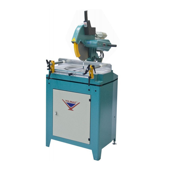
ALÜMİNYUM VE PVC KESME MAKİNESİ
:
YILMAZ
:
KD 350 / KD 400 M-D-P
:
:
:
2 YIL
:
30 İŞ GÜNÜ
:
:
:
:
:
1
Advertisement

Related Manuals for YILMAZ KD 350 M-D-P


Summary of Contents for YILMAZ KD 350 M-D-P
- Page 1 GARANTİ BELGESİ İMALATÇI FİRMA YILMAZ MAKİNE SANAYİ VE TİCARET A.Ş. ADRES TAŞDELEN MH. ATABEY CD. No 9 34788 ÇEKMEKÖY İSTANBUL-TÜRKİYE TELEFON 0216.312.28.28 PBX TELEFAX 0216.484.42.88 İMZA-KAŞE ÜRÜNÜN CİNSİ ALÜMİNYUM VE PVC KESME MAKİNESİ MARKASI YILMAZ MODEL KODU KD 350 / KD 400 M-D-P BANDROL/SERİ...
- Page 2 KESME DİYAGRAMI – CUTTING DIAGRAM – ДИАГРАММА ВЫПИЛИВАНИЯ KD 350 M/D/P...
- Page 3 KD 400 M/D/P...
- Page 4 ELEKTRİK ŞEMASI - WIRING DIAGRAM - ДИАГРАММА ЭЛЕКТРОПРОВОДКИ 230V 1P...
- Page 5 400V 3P...
- Page 6 BOYUTLAR – DIMENSIONS – РАЗМЕРЫ...
- Page 7 PARÇA LİSTESİ - PART LIST - ПЕРЕЧЕНЬ ДЕТАЛЕЙ RESİM-FIGURE-РИСУНОК 1...
- Page 8 RESİM-FIGURE-РИСУНОК 2...
- Page 9 STOK KODU / CODE ADET / QTY STOK KODU / CODE ADET / QTY номер ПОРЯДОК КОД КОЛИЧЕСТВО номер ПОРЯДОК КОД КОЛИЧЕСТВО 1SA010000-0060 1SK010000-0003 (KD 350) 2TU012610-0094 1SK010000-0004 (KD 400) 1PL030000-0017 2TU011110-1018 2TU011610-0009 1EL070001-0002 (230 V) 2TU012610-0102 1EL070001-0001 (400 V) 2TU011441-0043 2TU012110-0029 3UA030030-0003...
- Page 10 2TU012610-0009 3UA090030-0008 2TU011110-0145 1SR070000-0007 (KD 350) 1SR070000-0006 (KD 400) 1SC071000-0005 1SC041000-0014 1SC131000-0006 1SC011000-0002 1SC0210000-0050 1SC011000-0036 2TU012610-0053 2TU012610-0010 1PN010000-0157...
- Page 11 YEDEK PARÇA LİSTESİ / SPARE PART LIST / СПИСОК ЗАПАСНЫХ ЧАСТЕЙ PARÇA RESİM PARÇA ADI – PART NAME STOK KODU / CODE PICTURE НАИМЕНОВАНИЕ ДЕТАЛИ PART NO ПОРЯДОК КОД РИСУНОК НОМЕР DIŞ KAPLİN 2TU011441-0651 COUPLIN TESTERE KAPLİNİ 2TU011710-0006 SAW COUPLIN ÇATAL 3UA320030-0002 CLEVIS...
- Page 12 2TU012610-0009 / 0053 (KD 350-400 M/D) MENGENE YATAĞI 2TU012610-0010 / 0054 (KD 350-400 P/PS) CLAMP MOUNTING BRACKET 3UA060030-0013 PNÖMATİK MENGENE (KD 350-400 P/PS) PNEUMATIC CLAMP 3UA090030-0008 MEKANİK MENGENE (KD 350-400 M/D) MECHANIC CLAMP M8x32 PİPO 3UA040030-0007 M8x32 HANDLE M10*50 PİPO 3UA040030-0002 M12*60 HANDLE 1SK010000-0003 (KD 350)
- Page 13 SPRAYER SU PÜSKÜRTME 1PN010000-0012 VALF (KD 350-400 PS) WATER SPRAY VALVE 6204 RULMAN 1SR010000-0005 6204 BEARING 1SR070000-0007 (KD 350) MOTOR KAYIŞI 1SR070000-0006 (KD 400) MOTOR BELT MENGENE PABUCU 75-1 1PL010000-0033 CLAMP FEET 1PL010000-0042 HANDLE...
- Page 14 ŞALTER 66-1 1EL090000-0017 SWITCH 1EL070001-0002 (230V-1P 50 Hz) 1EL070001-0017 (240V-1P 50 Hz) MOTOR 1EL070001-0019 (220V-1P 60 Hz) MOTOR 1EL070001-0001 (400V-415V 3P 50 Hz) (440V-3P 60 Hz) ŞARTLANDIRICI 3UA110030-0020 LUBRICATOR AZ 431 MP VALF 1PN0140000-0157 AZ 431 MP VALVE...
-
Page 15: General Information
The technical drawings and details contained in this manual constitute a guide for the operator. 1.2. Service Information In case of any technical problem please contact your nearest YILMAZ dealer, or YILMAZ head office through the above mentioned phone, fax or e-mail address. - Page 16 AUTHORIZED TECHNICAL SERVICE CENTER ADDRESS TAŞDELEN MH. ATABEY CD. No 9 34788 ÇEKMEKÖY – İSTANBUL / TÜRKİYE 0216 312 28 28 Pbx. 0216 484 42 88 E-mail service@yilmazmachine.com.tr www.yilmazmachine.com.tr For minimize the documantation, It is wery necessary to mention below details at the agreements signed with suppliers and dealers of the purchased machines ...
- Page 17 2. SAFETY 2.1. Safety Symbols and Their Meanings Ensure safe working position, always keep your Read the user guide balance. Wear ear protectors Elektrical excitation Wear safety goggles Don’t place your hands between parts in motion.. If the power cable should be damaged during operation, don't touch and unplug it.
- Page 18 2.2. Accidents Prevention 2.2.1 Our machines are manufactured in accordance with CE safety directives, which cover national and international safety directives. 2.2.2 It is the task of the employer to warn his staff against accident risks, to train them on prevention of accidents, to provide for necessary safety equipment and devices for the operator’s safety.
- Page 19 2.3.4 Do not leave any things on the machine. 2.3.5 Don’t use any materials other than those recommended by the manufacturer for cutting operations on the machine. 2.3.6 Ensure that the work piece is clamped appropriately by the machine's clamp or vice 2.3.7 Ensure safe working position, always keep your balance.
- Page 20 3. MACHINE’S DESCRIPTION Mitre cutting machines designed for straight and angle cutting of PVC and Aluminium profiles. Cutting at angles of 15 -22,5 KD 350-400 M : Portable with manual clamps, cutting is manual. KD 350-400 D : Stationary with manual clamps, cutting is manual. ...
-
Page 21: Installation Of The Machine
5. INSTALLATION OF THE MACHINE 5.1 Preparation 5.1.1 The machine size and weight measurements, given the technical specification sheet.The ground, where the machine will be placed, should be even, solid enough to bear the weight of the machine. 5.1.2 The machine should be located approx. 50 cm away from the rear wall. The power connection plug of the machine is located on the rear side of the machine. - Page 22 5.2 Connecting to Power Source 5.2.1 Electrical connection must be made by a licensed electrician 5.2.2 The power outlet socket on the machine should be available. 5.2.3 Plug the machine to a grounded socket. 5.2.4 Mains voltage of the machine is optional as 230 V 50 Hz or 400 V 50 Hz. 5.2.5 Check the supply voltage.
-
Page 23: Operation
6.6 Keep foreign materials away from the working area of the machine, keep away from the machine’s moving parts. 6.7 Do not work on the machine by removing the protective parts. The safety data have been defined above. In order to prevent physical damage or damage to the equipment, please read the safety information carefully and keep the manual always in an easy accessible place. - Page 24 7.1.8 Do not process the profile before clamping the work piece properly. 7.1.9 While making cutting on the machine, be careful about clamps’ being out of the cutting area of the saw. TRUE FALSE...
- Page 25 7.2 Operation 7.2.1 Place PVC or aluminum profile that you are going to process on to the table (FIGURE 1 NO.5). Fix it with clamps (FIGURE 1 NO.75 / 88) on the table. 7.2.2 KD 350-400 M/D: The clamping is manual. KD 350-400 P: Clamping is pneumatically You can adjust forward- backward, up-down position of the clamps with special clamping parts (FIGURE 1 NO.77/78).
-
Page 26: Maintenance, Service And Repair
7.3 Angular cutting 7.3.1 Loosen the special clamping screw (FIGURE 2 NO.89) on set square (FIGURE 1 NO.25) 7.3.2 Pull the spring shaft (FIGURE 1 NO.23) from spring slot. At the same time, get the head (FIGURE 1 NO.33) at the level you want with the aid of plastic arm (FIGURE 1 NO.64) with your other hand. - Page 27 8.2 Changing the cutting tool 8.2.1 Cut the electric connection of the machine. 8.2.2 Dismantle the blade guard group (FIGURE 2 N0.47) in the stipulated order. 8.2.3 Remove the segment (FIGURE 2 NO.96) on the protection sheet bar (FIGURE 2 NO.42). Set the end of the protection sheet bar to off-position by removing it from the pin.
- Page 28 8.2.12 During saw blade change operations, use protective gloves 8.2.13 Saw must be selected according to standart DIN EN 847-1 8.2.14 A saw blade rotating in reverse direction, causes danger both for the operator and the equipment. The teeth of the saw blade would be damaged and even broken. 8.3 Changing the belt 8.3.1 Cut the electric connection of the machine.
- Page 29 8.3.8 Tighten the motor connection bolts. (FIGURE 2 NO.100) 8.3.9 Fix the removed parts by following the reverse sequence that your removed them before. 8.4 Angular and run out adjustment control of saw blade and set sguare 8.4.1 Cut the electric connection of the machine. 8.4.2 Control the run out of the saw blade with eyes.
- Page 30 Adjust the air pressure (pneumatic systems) 8.5.1 Pull up pressure adjustment valve. Set adjustment valve to the desired value on manometer by turning it clockwise or counter clockwise. Then lock the valve by pressing it down. 8.5.2 Set the air pressure between 6 and 8 BAR. If air pressure drops below the stated values, accessories operating with pneumatic power do not work.
-
Page 31: Troubleshooting Guide
9. TROUBLESHOOTING GUIDE Here are some recommendations for solving urgent problems. If the trouble cannot be solved, or if you have a problem other than those described hereunder, please contact our technical service or your nearest dealer. TROUBLE CAUSES REMEDY Lubricating the saw blade cutting Low surface quality (at aluminum Not cooling the saw blade surfaces... -
Page 32: Warranty Conditions
10. WARRANTY CONDITIONS YILMAZ Machine Industry and Trade Limited Company, guarantees that all machines have been tested and conform to the international standards. The guarantee is valid 24 months from despatch date and does not cover the electrical parts of the machine. - Page 33 ELECTRIC&PNEUMATIC DİAGRAM...
- Page 34 3 PHASE ELECTRICAL DIAGRAM SHEET 1...
- Page 35 1 PHASE ELECTRICAL DIAGRAM SHEET 1...
- Page 36 PNEUMATIC DIAGRAM SHEET 1...
- Page 37 PNEUMATIC DIAGRAM COOLING SYSTEM SHEET 1...
- Page 38 PNEUMATIC DIAGRAM CE SHEET 1...
Need help?
Do you have a question about the KD 350 M-D-P and is the answer not in the manual?
Questions and answers