Table of Contents
Advertisement
Quick Links
Advertisement
Table of Contents

Related Manuals for YILMAZ CK 412


Summary of Contents for YILMAZ CK 412
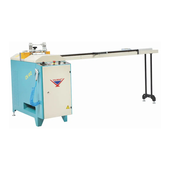
- Page 1 CK 412 AUTOMATIC GLAZING BEAD CUTTING SAW MACHINE USER MANUAL -...
- Page 2 YILMAZ ADRES TELEFON 0216.312.28.28 PBX TELEFAX 0216.484.42.88 MARKASI YILMAZ MODEL KODU CK 412 2 YIL ADRES TELEFON TELEFAX...
- Page 3 TECHNICAL FEATURES - 3000 = 110 mm W = 54 1200 W x 2 50 Hz 800 W x 2 50 Hz CK 412 =200 mm L = 113 D/dak. 6/8 Bar Lt. / dak. 400 V AC 3 P PE...
- Page 4 BOYUTLAR DIMENSIONS -PICTURE-...
- Page 5 - PART LIST - -PICTURE- - PICTURE -...
- Page 6 - PICTURE- - PICTURE- - PICTURE-...
- Page 7 STOK KODU ADET STOK KODU ADET STOCK CODE STOCK CODE 1SK010000-0001 2TU012210-1016 2TU012510-0392 76/1 1PN020000-0191 2TU012510-0308 76/2 2TU011110-1135 2TU012510-0311 76/3 2TU011441-0720 1SA010000-0051 76/4 2TU014010-0198 1SA030000-0091 76/5 2TU011441-0709 2TU014010-0093 76/6 2TU011441-0719 2TU011441-0289 2TU012310-0103 1SA030000-0090 2TU012210-1047 1SA050000-0152 2TU012210-0906 1SA020000-0026 1SK010000-0008 1PL020000-0008 3UA010030-0097 2TU011210-0643: 3UA730030-0008 1PN020000-0122...
- Page 8 STOK KODU / CODE PICTURE PART NO 1EL090000-0003...
-
Page 10: Table Of Contents
ENGLISH CONTENTS 1. General information 1.1. Introduction 1.2. Service Information 2. Safety 2.1. Safety Symbols and Their Meanings 2.2. Accidents Prevention 2.3. General Safety Information 4. Transport of the Machine 5. Installation of the Machine 5.1. Preparation 5.2. Connecting to Power Source 7. -
Page 11: General Information
The technical drawings and details contained in this manual constitute a guide for the operator. 1.2. Service Information In case of any technical problem please contact your nearest YILMAZ dealer, or YILMAZ head office through the above mentioned phone, fax or e-mail address. - Page 12 AUTHORIZED TECHNICAL SERVICE CENTER ADDRESS 0216 312 28 28 Pbx. 0216 484 42 88 E-mail service@yilmazmachine.com.tr www.yilmazmachine.com.tr For minimize the documantation, It is wery necessary to mention below details at the agreements signed with suppliers and dealers of the purchased machines Machine model Voltage and frequency Date of purchase...
-
Page 13: Safety
2. SAFETY 2.1. Safety Symbols and Their Meanings Ensure safe working position, always keep your Read the user guide balance. Wear ear protectors Elektrical excitation Wear safety goggles If the power cable should be damaged during operation, don't touch and unplug it. High temperature warning Never use damaged power cables. -
Page 14: Accidents Prevention
2.1. Accidents Prevention 2.2.1 Our machines are manufactured in accordance with CE safety directives, which cover national and international safety directives. 2.2.2 It is the task of the employer to warn his staff against accident risks, to train them on prevention of accidents, to 2.2.3 It is the task of the employer to warn his staff against accident risks, to train them on prevention of accidents, to provide for necessary safety equipment and devices f 2.2.4 Machine should be operated only by staff members, who have read and understood the contents of this manual. - Page 15 2.3.4 Use correct illumination for the safety of the operator. ( ISO 8995-89 Standard The lighting of indoor work system) 2.3.5 machine. 2.3.6 Ensure that the work piece is clamped appropriately by the machine's clamp or vice 2.3.7 Ensure safe working position, always keep your balance. 2.3.8 Keep your machine always clean for safe operation.
-
Page 16: Transport Of The Machine
DESCRIPTION Cut the PVC window lath profiles for 45 degree.profiles Clamping system is pneumatic, while cutting is automatic. Cutting speed is adjustable. After finishing the cutting operation the saw blades return to their original position automatically. Allows to cut 8 different bar profiles by using single mold Allows cutting 2 similar bar profiles at one attempt.. -
Page 17: Installation Of The Machine
5. INSTALLATION OF THE MACHINE 5.1 Preparation 5.1.1 The machine size and weight measurements, given the technical specification sheet.The ground, where the machine will be placed, should be even, solid enough to bear the weight of the machine 5.1.2 The machine should be located approx. 50 cm away from the rear wall 5.1.3 You can provide the balance of the machine with adjustable counterforts in the bottom part. - Page 18 5.2.6 After electrical connection is made, machine must be operated in idle running and it must be controlled whether rotation directions of cutting tools are correct or not and if the rotation direction is wrong, appropriate connection must be made. 6.
-
Page 19: Operation
7.1.2 Clean all surfaces of the machine from chip and foreign particles. Use eye glasses for protection. 7.1.3 The CK 412 Automatic Glazing Bead Saw has been designed for cutting of aluminum and PVC glazing beads at 7.1.4 Control whether cutting tools are inserted safely to their places. - Page 20 7.2.3 Align supporting plate (PICTURE 7 NO. 76/5) on the gasket side of bar profile by moving forth and back 7.2.4 Clench the profile by rotating the clamp handle NOTE: In order to have a correct measurement and cut, imaginary lines passing through A and B should be perpendicular to each other as shown in PICTURE 7 7.2.5 After aligning the profile with the plate, place the bolt, which is on the scaled measurement section (PICTURE 7 NO: 76) on to the bolt, which is provided with a preset value on setsquare (PICTURE 7, NO.
-
Page 21: Use Of The Ka 200 Easy Measuring Apparatus
7.2.7 Start the electrical motor by pressing the motor start button. (PICTURE 6 NO.36) 7.2.8 Begin the cutting operation by pressing the cutting start button (PICTURE 6 NO.35). The machine automatically performs cutting operation and returns back to its starting position. Stop the electirical motor by pressing the motor stop button. -
Page 22: Maintenance, Service And Repair
PICTURE 8 8. MAINTENANCE, SERVICE AND REPAIR 8.1 Maintenance 8.1.1 Cut the electric and pneumatic power connections of the machine. 8.1.2 Clean all surfaces of the machine from burs, chips and foreign substances. If the machine will not be used for a long time, lubricate undyed parts with oil that prevents rusting. -
Page 23: Changing The Cutting Tool
8.2 Changing the cutting tool 8.2.1 Use protective gloves when replacing Saw 8.2.2 Cut the electric connection of the machine. 8.2.3 Open the upper protection covers. 8.2.4 Take out the nuts by using 8mm llen wrench and 22 mm. wrench as shown at the photo PICTURE-9 8.2.5 Remove the connection parts of cutting set in the right order. -
Page 24: Adjust The Air Pressure
NOTE: Ensure that the saw blades rotate in correct direction (the correct direction has been marked on 8.2.8 8.2.9 The saw selection should be made proper to EN 847-1 Standard. Adjust the air pressure (pneumatic systems) 8.3.1 Pull up pressure adjustment valve. Set adjustment valve to the desired value on manometer by turning it clockwise or counter clockwise. - Page 25 Material PVC (Glass bead profile 80 dB (Measured Value) Lenght 2000 mm. 93 dB (Average Sound Pressure Value Width 22 mm. 2 dB (Uncertainity in the Measurements) Height 20 mm. The values given fort he noise are the emission level and it does not show that it in the safe working level. A connection between emission and exposure levels is available, however it is not used confidently for the determination whether these more advanced precautions are necessary or not.
-
Page 26: Warranty Conditions
10. WARRANTY CONDITIONS YILMAZ Machine Industry and Trade Limited Company, guarantees that all machines have been tested and conform to the international standards. The guarantee is valid 24 months from despatch date and does not cover the electrical parts of the machine. - Page 27 ELECTRIC&PNEUMATIC...
- Page 28 CK 412 3 PHASE ELECTRICAL DIAGRAM SHEET 1...
- Page 29 CK 412 3 PHASE ELECTRICAL DIAGRAM SHEET 2...
- Page 30 CK 412 1 PHASE ELECTRICAL DIAGRAM SHEET 1...
- Page 31 CK 412 1 PHASE ELECTRICAL DIAGRAM SHEET 2...
- Page 32 CK 412 PNEUMATIC DIAGRAM SHEET 1...
Need help?
Do you have a question about the CK 412 and is the answer not in the manual?
Questions and answers