
Related Manuals for Advantech SPC-821-6 Series


Summary of Contents for Advantech SPC-821-6 Series
- Page 1 User Manual SPC-815 SPC-821 電腦 Multi-Touch Panel Computer with Intel Skylake Processor &Extension Units...
- Page 2 The documentation and the software included with this product are copyrighted 2020 by Advantech Co., Ltd. All rights are reserved. Advantech Co., Ltd. reserves the right to improve the products described in this manual at any time without notice. No part of this manual may be reproduced, copied, translated, or transmitted in any form or by any means without the prior written permission of Advantech Co., Ltd.
- Page 3 Product Warranty (2 years) Advantech warrants the original purchaser that each of its products will be free from defects in materials and workmanship for two years from the date of purchase. This warranty does not apply to any products that have been repaired or altered by persons other than repair personnel authorized by Advantech, or products that have been subject to misuse, abuse, accident, or improper installation.
- Page 4 This product has passed the CE test for environmental specifications when shielded cables are used for external wiring. We recommend the use of shielded cables. This type of cable is available from Advantech. Please contact your local supplier for ordering information.
- Page 5 Safety Instructions Read these safety instructions carefully. Retain this user manual for future reference. Disconnect this equipment from any AC outlet before cleaning. Use a damp cloth for cleaning. Do not use liquid or spray detergents. For pluggable equipment, the power outlet socket should be located near the equipment and easily accessible.
- Page 6 Le niveau de la pression acoustique à la position de l'opérateur, conformément à la norme CEI 704-1: 1982, ne dépasse pas 70 dB (A). AVIS DE NON-RESPONSABILITÉ: Cet ensemble d'instructions est donné conformé- ment à la CEI 704-1. Advantech décline toute responsabilité quant à l'exactitude des déclarations contenues dans ce document. –...
- Page 7 MÊME TYPE OU ÉQUIVALENT RECOMMANDÉ PAR LE FAB- RICANT, JETER LES BATTERIES USÉES SELON LES INSTRUCTIONS DU FABRICANT. VEUILLEZ CONTACTER LE FABRICANT, ADVANTECH, POUR LE REMPLACER. ATTENTION! Pour éviter les chocs. Ne pas retirer lecouvercle. Aucune pièce réparable par l’utilisa- teur. Pour l’entertien adressez-vours aux personnes qulifiées, s.v.p.
- Page 8 安全指示 請仔細閱讀此安全操作說明。 請妥善保存此用戶手冊供日後參考。 用濕抹布清洗設備前,請確認拔除電源線。請勿使用液體或去污噴霧劑清洗設 備。 對於使用電源線的設備,設備周圍必須有容易接觸到的電源插座。 請勿在潮濕環境中試用設備。 請在安裝前確保設備放置在可靠的平面上,意外摔落可能會導致設備損壞。 設備機殼的開孔適用於空氣對,從而防止設備過熱。請勿覆蓋開孔。 當您連接設備到電源插座前,請確認電源插座的電壓符合要求。 請將電源線佈置在人們不易絆倒的位置,請勿在電源線上覆蓋任何雜物。 請注意設備上所有的警告標示。 如果長時間不使用設備,請拔除與電源插座的連結,避免設備被超標的電壓波動 損壞。 請勿讓任何液體流入通風口,以免引起火灾或短路。 請勿自行打開設備。為了確保您的安全,請透過經認證的工程師來打開設備。 如遇下列情况,請由專業人員維修: – 電源線或插頭損壞; – 設備內部有液體流入; – 設備曾暴露在過度潮濕環境中使用; – 設備無法正常工作,或您無法透過用戶手冊來正常工作; – 設備摔落或損壞; – 設備有明顯外觀損; 請勿將設備放置在超出建議溫度範圍的環境,即不要低於 -20 ℃ (-4 ℉)或高 於 60 ℃ (140 ℉) ,否則可能會造成設備損壞。 注意:若電池更換不正確,將有爆炸危險。因此,只可以使用製造商推薦的同一...
-
Page 9: Table Of Contents
Contents Chapter General Information ......1 Introduction ....................2 Packing List....................3 Specifications .................... 3 1.3.1 System Kernel................3 1.3.2 I/O Ports..................3 1.3.3 Safety and Environment..............3 Panel PC Specifications................4 1.4.1 Without Button extension for built in SPC-815-6X3AG & SPC-821- 6X3AG Panel PC ................ - Page 10 SPC-800 User Manual...
-
Page 11: Chapter 1 General Information
Chapter General Information... -
Page 12: Introduction
Introduction The SPC-800 series devices with a brand-new ID design can support an all-around IP65 waterproof casting design with general I/O connectors, with I/O cover all the wir- ing & cabling can be hidden invisible to ensure reliability & field wire simplicity. SPC-800 is a hardware-solution based HMI product which supports industrial grade ARM/VESA mount system and push button extension supported. -
Page 13: Packing List
Packing List 1 x System 1 x Plug-In Block 1 x Ground Wire (100CM) 4 x SSD screws 1 x Cover IO 1 x SPC Driver DVD 1 x Registration and Warranty Card 4 x Pole Mounting Blake Screws ... -
Page 14: Panel Pc Specifications
Panel PC Specifications 1.4.1 Without Button extension for built in SPC-815-6X3AG & SPC- 821-6X3AG Panel PC SPC-815 SPC-821 Advantech Part Number SPC-815- SPC-815- SPC-815- SPC-821- SPC-821- SPC-821- 633AG 653AG 673AG 633AG 653AG 673AG 7.83 Kg(W/O ARM Mount) 10.63Kg(W/O ARM Mount) Weight 8.2 Kg(W ARM Mount) - Page 15 Display Type TFT LCD TFT LCD Display Size 15.6" 16:9 21.5" 16:9 HD 1366 X 768/FHD 1920 Max. Resolution FHD 1920x1080 X1080 LCD Luminance (cd/m²) Display Backlight MTBF 50,000 (hrs) Touch screen Projected capacitive 10 point multitouch Horizontal 170° / 170° 178°...
-
Page 16: Button Extension For Built In Spc-815-6X3Ap & Spc-821-6X3Ap Panel Pc
1.4.2 Button extension for built in SPC-815-6X3AP & SPC-821- 6X3AP Panel PC SPC-815 SPC-821 Advantech Part Number SPC-815- SPC-815- SPC-815- SPC-821- SPC-821- SPC-821- 633AP 653AP 673AP 633AP 653AP 673AP 7.83 Kg(W/O ARM Mount) 10.63Kg(W/O ARM Mount) Weight 8.2 Kg(W ARM Mount) 11 Kg(W ARM Mount) 8.63Kg(W Vesa Mount) -
Page 17: Power
This product is intended to be supplied by a Listed Power Adapter or DC power source, rated 24Vdc, 2.5A minimum and TMA 55 degree C minimum, if need further assistance, please contact Advantech for further information. SPC-800 User Manual... -
Page 18: I/O Ports Arrangement
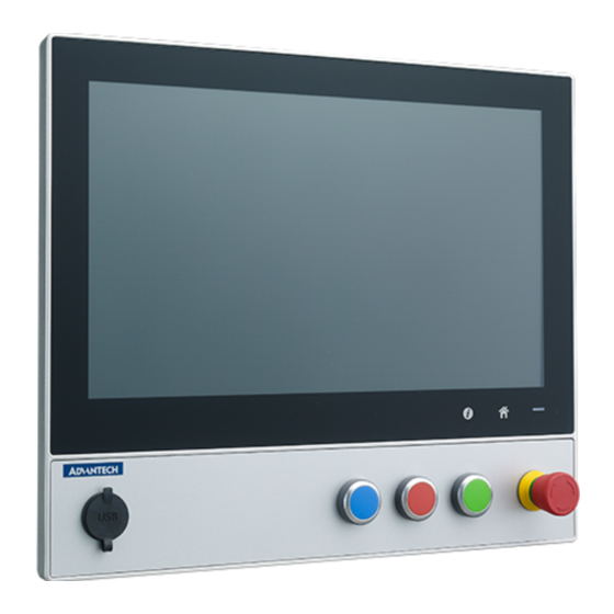
I/O Ports Arrangement The arrangement of the I/O ports is shown in Figure 1.1. Figure 1.1 SPC-800 Front view and Side view Figure 1.2 SPC-800 Rear View- I/O Port Arrangement SPC-800 User Manual... -
Page 19: Hardware Specifications
Hardware Specifications SPC-815 Weight: 7.83kg Dimensions (W x H x D): 402x 333 x 67mm (15.83" x 13.11" x 2.64") Figure 1.3 SPC-815 Dimensions SPC-800 User Manual... - Page 20 SPC-821 Weight: 10.63kg Dimensions (W x H x D): 547 x 420 x 67 mm (21.54” x 16.54” x 2.64”) Figure 1.4 SPC-821 Dimensions SPC-800 User Manual...
-
Page 21: Chapter 2 System Setup
Chapter System Setup... -
Page 22: Scope Of Delivery
Scope of Delivery You can easily get SPC-800 started by following the below steps. The SPC-800 series. Unpack the SPC package. Check the packing list at the beginning of this manual to make sure all items have been included. Figure 2.1 Unpack the Package The following components are included in the scope of delivery of the SPC-800 device. -
Page 23: Pole Mount Kit Box
2.1.2 Pole Mount Kit BOX Name Figure Qty Name Figure Pole Mount- Cover IO ing Black Screw System Setup SPC-800 devices install Cover IO The Base Unit standard product contains SPC-800 device, Cover IO and ARM screws. Fix 2 pcs with M5 x 10 screws on the Cover IO screw hole location (Do not fas- ten screw) Place Cover IO to product and fasten 2pcs Screws. - Page 24 SPC-800 devices install SSD Remove the M3 x 6pcs screws from the PCBA bracket. Remove the M3 x 1pc screw from the SSD bracket. And pull the SSD bracket to the right side. SPC-800 User Manual...
- Page 25 Install the SSD into the SSD bracket and fix it with the M3 x 4pcs screw. a. Place the SSD bracket to the position in the device. (There are two Pins that can hold the SSD bracket against Pin) b. Pull it to the left to confirm that the iron part is fixed with the middle bracket. c.
-
Page 26: Mounting The Spc-800 Device
The SPC-800 devices are designed for mounting with the base cover IO. If you install the device with an ARM mounting, you must the corre- sponding relative size and screw hole position can support the weight of the device or purchase a pole with Advantech Requirement Pole Mount x 1pc ... - Page 27 Installation Procedure Loosen the M3 x 4pcs screws of IO Bracket. Attach the IO with M5 or M6 x 4pcs screws to the interface of the support pole mount. Fasten the OP bracket with cover IO by the screw. SPC-800 User Manual...
- Page 28 Attach the device with M5x 4pcs screws to the IO from back side. Make sure that the connection cables whether put into the pole mount. Installation Procedure (Pendant and Pedestal mounting) Loosen the M5 x 4pcs screws from IO (Pedestal mount) Attach the device with M5x 4pcs screws to the IO from the back side.
-
Page 29: Spc-800 Device For Support Vesa Mounting
2.3.2 SPC-800 device for support VESA Mounting Note! Base Unit Product accessory without a VESA mounting and Cable Entry The SPC-800 devices are designed for mounting with the base cover IO. If you install the device with a VESA mounting, you must use 100 x100 standard VESA compliant hole to allow wall and accessory mount- ing option and can purchase the cable suitable for you through Advant- ech Entry... - Page 30 Cable Entry x 1pcs (Choose the suitable for equipment application) Item Product Specifications Figure Rating Split cable entry system KEL-ER-E5 for rout- IP65 ing and Sealing up to 5 cables with connector IP66 (Cable diameters from 1 to 16 mm) Split cable entry system KEL-ER 10 for rout- ing and sealing cables with connectors, IP65...
- Page 31 Installation Procedure Install VESA ARM to the VESA adapter by M4 x 4pcs screws. Fix 2 pcs of M5 screws into upside screw holes. SPC-800 User Manual...
- Page 32 Fit into two holes with two screws Fix 2 pcs of M5 screw into the body through the holes downside in the VESA kit. SPC-800 User Manual...
- Page 33 Arrange the cables through the opening of the cover and fix the cover by M5 x 4pcs screws. Fix the cables in the entry frame by 3pcs M5 screws and fix the entry to body by 2pcs M5 screws. Fix the cover to body by 6pcs M3 screws. SPC-800 User Manual...
- Page 34 Move the unit from downside to upside of VESA kit. And move the upside 2 screws to the screw holes downside of VESA kit. Finally, tighten the 4 screws. SPC-800 User Manual...
-
Page 35: Spc-800 Extension With Operator Controls
SPC-800 device with operator controls extension can order these components (Push Button, PCBA, terminal plug and Screw) do it by yourself assembly or Comprehen- sive assembly also via Advantech (Build To Order) Base Unit design for Extension Unit The Base Unit design is support to RAFI RAFIX 22 Buttons, and the rightmost button is reserved for Emergency Stop Button Push-button. - Page 36 Push Button with Extension Unit(Use All Button), Extension Unit 15” and 21”, base unit operator controls from right to left location design is Emergency Stop Button, Red Push Button, Black Push Button, Blue Push Button, the other button color is White and USB Freely configuration do it by yourself assembly ...
- Page 37 Push Button of Type Description Picture RAFIX 22 FS+ - Emergency stop pushbutton, not illuminable, reset by rotation, red arrows 1.30.273.511/0300 RAFIX 22 FS+ - Pushbutton, illuminated, flush lens, round collar, metal front ring, momentary 1.30.270.021/2200 RAFIX 22 FS+ - Drucktaster nicht beleuchtbar , flache Blende, Bund rund, Frontring Metall, tastend 1.30.270.021/0100 RAFIX 22 FS+ - Pushbutton, illuminated, flush lens, round collar,...
- Page 38 Type of Button's PCBA (include PCBA/Lamp Optional) Description Picture RAFIX 22 FS+- Universal contact block, silver contacts, 1 NC, 1NO 1.20.126.203/0000 RAFIX 22 FS+- Emergency stop contact block, silver contacts, 2 NC 1.20.126.604/0000 Installation Procedure Loosen the M5 x 4pcs screw of IO and remove the IO Loosen the M3 x6pcs screw and loosen the M3 x6pcs screw of OP back side Note! SPC-815 series are need loosen M3 x16L *4pcs and M3 x 6L*4pcs of...
- Page 39 Pre-hole cut-outs Fix the RAFI button assembly of the threaded ring. Attach the Button’s PCBA with M3 x 4pcs screw to the OP back side. Fasten the OP back side by the screw. SPC-800 User Manual...
-
Page 40: Installing The Drivers
SPC-815/821 will use built-in PCT touch driver of OS If operating under Windows 10. 2.5.2 Installation of Watchdog driver Run the Setup program. When the setup program is running, click the “Next >” button in "Advantech Watchdog Driver Setup Wizard". SPC-800 User Manual... - Page 41 The installation is running. Please wait for completion. Click the "Install" button to continue the installation of Advantech Watchdog KMDF driver Click on "Restart" button or "Close" button on the "Advantech Watchdog Driver" to complete the setup program. SPC-800 User Manual...
-
Page 42: Installation Of Brightness Control Driver
After installing Watchdog driver, a "Watchdog Service Configuration" icon will show in control panel. 2.5.3 Installation of Brightness Control Driver Run the Setup program. When the setup program is running, click the “Next” button. SPC-800 User Manual... - Page 43 To continue the installation, check Always trust software from “Advantech Co., Ltd.” and click Install to complete the driver installation. The installation is running. Please wait for completion. Click Restart to reboot and finish the installation of Advantech Brightness Win- dows KMDF Driver. SPC-800 User Manual...
-
Page 44: Installation Of Ec Lmsensor Driver
After installing Brightness driver, a “Brightness Utility“ icon will show in control panel. 2.5.4 Installation of EC Lmsensor Driver Run the Setup program. Please install the AdvCOMMON driver first if the follow- ing error occurred during the installation. SPC-800 User Manual... - Page 45 When the setup program is running, click the "Next" button. To continue the installation, click the "Install" button. SPC-800 User Manual...
- Page 46 The installation is running. Please wait for completion. Click the "Restart" button to reboot and finish the installation of Advantech Lmsensor device driver. SPC-800 User Manual...
- Page 47 After installing Brightness driver, a "lmsensor Utility" icon will show in star pro- gram manual. SPC-800 User Manual...
- Page 48 SPC-800 User Manual...
-
Page 49: Chapter 3 Features Of Windows Embedded Os
Chapter Features of Windows Embedded OS... -
Page 50: Features In Windows Embedded Os
Applying changes to an image applies all changes made to the operat- ing system during a specific period of time. Advantech provides a utility to run EWF. Follow the steps outlined below to enable this function. Access Start Menu->All Programs->Advantech-> AdvWF and then click EWF Utility. -
Page 51: File-Based Write Filter (Fbwf)
Writes to folders with write-through exceptions will persist when the device is restarted. Advantech provides a utility to run FBWF. Follow the steps outlined below to enable this function. Access Start Menu->All Programs->Advantech->AdvWF and the click on FBWF Utility. - Page 52 Move the volume you want to protect from “Available Volume” to “Protected Vol- ume” and choose “Write-Through Files and Folders”. Click “Apply”. The system will reboot automatically, after which FBWF will be enabled. SPC-800 User Manual...
-
Page 53: Appendix Aui Operating Process
Appendix UI Operating Process... -
Page 54: Ui Operating Process
UI Operating Process This section is to introduce how to operate HMI utility(GL_Utility), you can download the utility from Advantech's product support portal of SPC-821/815 at http://support.advantech.com. See the process below: As you can find 2 function buttons in the lower right corner of front panel, represents "intelligent"... - Page 55 Long press Home Key-> Home - Long press to disable / enable touch function Note! When touch function is disabled, you'll see a message up in the lower right corner of screen SPC-800 User Manual...
- Page 56 One press Intelligent Key-> Intelligent - Advantech Intelligent Utility A. Quick start-> – Press "+" to add shortcut. – Long press the icon to perform "right click" until an "X" mark appears in upper right corner to "delete". SPC-800 User Manual...
- Page 57 B. Setting -> Password confirmation for authority confirmation when first log in, default password is “1234” without input order to active. – Setting - Home-key: Select an execute file to set up as "Home-key" App, in default path is to show “desktop”. –...
- Page 58 – Setting - Password: Change password function. SPC-800 User Manual...
- Page 59 C. System management-> – System information: Note! SPC-815/821 also provides open button code as following definition for customer's configuration to their Apps/SW applications. The codes are defined from general keyboard input. Table A.2: Button code definition One press Long press I key(icon) Ctrl+Shift+Alt+I Ctrl+Shift+Alt+U...
- Page 60 No part of this publication may be reproduced in any form or by any means, such as electronically, by photocopying, recording, or otherwise, without prior written permission from the publisher. All brand and product names are trademarks or registered trademarks of their respective companies. © Advantech Co., Ltd. 2020...
Need help?
Do you have a question about the SPC-821-6 Series and is the answer not in the manual?
Questions and answers