
Related Manuals for Advantech TPC-300 Series


Summary of Contents for Advantech TPC-300 Series
- Page 1 User Manual TPC-300 Series TPC-B510 Industrial Touch Panel Computer with 8th Gen. Intel® Core™ Processor...
- Page 2 No part of this manual may be reproduced, copied, translated or transmitted in any form or by any means without the prior written permission of Advantech Co., Ltd. Information provided in this manual is intended to be accurate and reliable. How- ever, Advantech Co., Ltd.
- Page 3 Product Warranty (2 years) Advantech warrants the original purchaser that each of its products will be free from defects in materials and workmanship for two years from the date of purchase. This warranty does not apply to any products that have been repaired or altered by persons other than repair personnel authorized by Advantech, or that have been sub- ject to misuse, abuse, accident, or improper installation.
- Page 4 甲類警語 警告使用者:這是甲類資訊產品,在居住的環境中使用時,可能會造成射頻干擾,在 這種情況下,使用者會被要求採取某些適當對策。 Technical Support and Assistance Visit the Advantech website at www.advantech.com/support to obtain the latest product information. Contact your distributor, sales representative, or Advantech customer service center for technical support if you need additional assistance. Please have the following information ready before calling: –...
- Page 5 In accordance with the IEC 704-1:1982 specifications, the sound pressure level at the operator’s position does not exceed 70 dB (A). TPC-300 Series, TPC-B510 User Manual...
- Page 6 DISCLAIMER: These instructions are provided in accordance with IEC 704-1 specifications. Advantech disclaims all responsibility for the accuracy of any statements contained herein. Document Feedback To assist us with improving this manual, we welcome all comments and constructive criticism. Please send all feedback in writing to support@advantech.com.
-
Page 7: Table Of Contents
Figure 3.1 Enabling UWF - Step 1..........22 Figure 3.2 Enabling UWF - Step 2..........23 UWF Overlay................... 23 Figure 3.3 UWF Overlay Settings - Step 1 ........ 24 Figure 3.4 UWF Overlay Settings - Step 2 ........ 24 TPC-300 Series/TPC-B510 User Manual... - Page 8 Intel Chipset Software Installation Utility..........44 Intel Graphics Driver Installation ............. 46 LAN Driver Installation ................49 Intel Management Engine Installation............. 52 Touch Driver Installation ................. 55 Appendix C BIOS Setup ........59 Entering Setup ..................60 TPC-300 Series/TPC-B510 User Manual viii...
- Page 9 C.1.1 Main Setup.................. 61 C.1.2 Advanced BIOS Features Setup..........62 C.1.3 Chipset Configuration ..............71 C.1.4 Security ..................73 C.1.5 Boot..................... 74 C.1.6 Save & Exit ................. 75 TPC-300 Series/TPC-B510 User Manual...
- Page 10 TPC-300 Series/TPC-B510 User Manual...
-
Page 11: Chapter 1 General Information
Chapter General Information... -
Page 12: Introduction
Introduction The TPC-300 series touch panel computers are human machine interfaces (HMIs) equipped with an Intel® Core™ i3-8145UE dual-core (2.20 GHz)/i5-8365UE quad- core (1.60 GHz)/i7-8665UE quad-core (1.70 GHz) processor and feature displays that range from 12” to 23.8” in size. -
Page 13: System Hardware
1 x 2.5” SATA SSD I/O Ports: – 2 x RS-232/422/485 – 1 x USB 2.0 – 4 x USB3.2 (Gen 2) – 1 x iDoor slot – 1 x DisplayPort (video output) – 1 x Audio Line-Out/Mic-In TPC-300 Series/TPC-B510 User Manual... -
Page 14: Lcd Panel
Display Type: FHD TFT LED LCD Display Size: 23.8” (16:9) Max. Resolution: 1920x1080 Max. Color: 16.7M Luminance (cd/m ): 350 Viewing Angle (H°/V°): 178°/178° Backlight Life: 50,000 hrs Contrast Ratio: 1000:1 TPC-300 Series/TPC-B510 User Manual... -
Page 15: Touchscreen
Ingress Protection: IP66-rated front panel Operating Temperature: -10 ~ 55 °C/14 ~ 131°F (without airflow) Storage Temperature: -20 ~ 70 °C/-4 ~ 158 °F Vibration Protection: With SSD: 1 Grms (5 ~ 500 Hz) (operating, random) TPC-300 Series/TPC-B510 User Manual... -
Page 16: Operating Systems
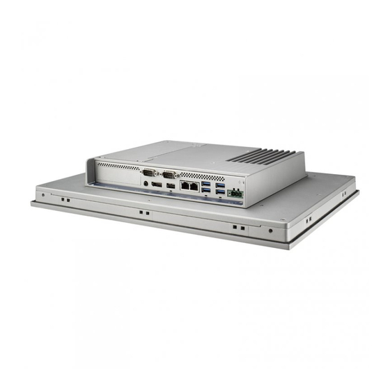
Android AdvLinux I/O Layout The I/O the layout for TPC-300 Series and TPC-B510 is shown in Figure 1.1. A. HDD/SSD bay (default) F. USB 2.0 B. iDoor slot G. LAN (10/100/1000) C. RS-232/422/485 H. USB 3.2 (Gen2) D. -
Page 17: Dimensions And Cutouts
Dimensions (L x W x H): 410.4 x 343.4 x 68 mm/16.16 x 13.52 x 2.68 in Cutout Dimensions (L x H): 303 x 229 mm/11.93 x 9.02 in 186.3 301.56 Figure 1.2 TPC-312 Dimensions TPC-300 Series/TPC-B510 User Manual... -
Page 18: Tpc-315 Series
Dimensions (L x W x H): 383.2 x 307.3 x 66.5 mm/15.09 x 12.1 x 2.62 in Cutout Dimensions (L x H): 374.5 x 298.5 mm/14.74 x 11.75 in 66.5 383.2 306.1 372.89 Figure 1.3 TPC-315 Dimensions TPC-300 Series/TPC-B510 User Manual... -
Page 19: Tpc-317 Series
Dimensions (L x W x H): 410.4 x 343.4 x 68 mm/16.16 x 13.52 x 2.68 in Cutout Dimensions (L x H): 401.3 x 334.8 mm/15.80 x 13.18 in 272.9 343.4 399.2 Figure 1.4 TPC-317 Dimensions TPC-300 Series/TPC-B510 User Manual... -
Page 20: Tpc-324W Series
Dimensions (L x W x H): 595.9 x 374.1 x 70 mm/23.46 x 14.73 x 2.76 in Cutout Dimensions (L x W): 587 x 365.3 mm/23.11 x 14.38 in 585.55 Figure 1.5 TPC-324W Dimensions TPC-300 Series/TPC-B510 User Manual... -
Page 21: Tpc-B510 Series
1.4.5 TPC-B510 Series Weight (Net): 2.6 kg/5.73 lb Dimensions (L x W x H): 269 x 203 x 40 mm/10.6 x 8.0 x 1.6 in 268.96 39.5 Figure 1.6 TPC-B510 Dimensions TPC-300 Series/TPC-B510 User Manual... - Page 22 TPC-300 Series/TPC-B510 User Manual...
-
Page 23: Chapter 2 Installation
Chapter Installation... -
Page 24: Transport And Unpacking
12 hours to allow the device to dry completely before switching it on. 2.1.2 Unpacking Unpack the TPC device. Connect the power connector to the 24 V power lines of a power adapter or in-house power source. Figure 2.1 Power Connector and Power Lines TPC-300 Series/TPC-B510 User Manual... -
Page 25: Panel Mounting
Figure 2.2 Power Connector Plug the power lines into the system power receptor. Power on the system. Calibrate the touchscreen. Panel Mounting Position the TPC panel computer against the panel mount. Figure 2.3 Panel Mounting – Positioning TPC-300 Series/TPC-B510 User Manual... - Page 26 Figure 2.4 Panel Mounting – Clamp Attachment Secure the clamps in place using the M4 x 25L screws provided in the acces- sory box. Torque: 5 kgf-cm (0.5 Nm) Figure 2.5 Panel Mounting – Clamp Fixing TPC-300 Series/TPC-B510 User Manual...
-
Page 27: Vesa Mounting
VESA Mounting The TPC-300 series and TPC-B510 support VESA mounting (100x100). M4 x 10 screws are recommended for attaching the TPC devices to the VESA mount bracket. Affix the VESA mount bracket at the top of the rear of the TPC device and fasten in place using four M4 screws. -
Page 28: Cabinet Installation
Connect the ground pin of TPC device to the cabinet. Connect the I/O to the controller if needed. Connect the V+ and V- of the power supply to the TPC device. After completing the above steps, activate the power supply. TPC-300 Series/TPC-B510 User Manual... - Page 29 Note! If a USB device or mini PCIe card is installed in the TPC device, double check the voltage between V- and earth/ground. If the voltage is not equal, short the V- and earth/ground wires. TPC-300 Series/TPC-B510 User Manual...
-
Page 30: Power/Digital Ground And Earth/Ground
Use of a third-party device or cable can disrupt Level 1 isolation. In such circum- stances, users should short all grounds (Power GND/Digital GND/Earth GND) and ensure adequate earth/ground connection. TPC-300 Series/TPC-B510 User Manual... -
Page 31: Chapter 3 Windows Embedded Features
Chapter Windows Embedded Features... -
Page 32: Windows Embedded Features
UWF fully supports the NTFS file system; however, during device startup, NTFS file system journal files can write to a protected volume before UWF has loaded and started protecting the volume. Advantech provides a utility to operate UWF. Refer to the steps below to enable the utility. -
Page 33: Uwf Overlay
UWF can store the overlay either entirely on RAM (RAM-based) or in a pre-allocated file on the system volume (disk-based). Advantech provides a utility for configuring a UWF overlay. Refer to the steps below to enable this function. - Page 34 Click Start Menu -> Advantech -> AdvELM -> Overlay Settings Figure 3.3 UWF Overlay Settings - Step 1 Input the desired size (MB). Important When setting up a RAM-based overlay, be sure to leave sufficient available RAM to meet the minimum RAM requirements for system operation.
- Page 35 Select the mode (RAM or Disk). Figure 3.5 UWF Overlay Settings - Step 3 Click OK or Apply. Figure 3.6 UWF Overlay Settings - Step 4 TPC-300 Series/TPC-B510 User Manual...
-
Page 36: Horm
The installation procedure for UEFI always creates a hidden system par- tition and the UWF cannot protect hidden partitions. Because HORM requires all fixed partitions to be protected, HORM cannot be used on any devices that con- tain a hidden partition, including UEFI-capable devices. TPC-300 Series/TPC-B510 User Manual... - Page 37 Click Start Menu -> Advantech -> Embedded Lockdown Manager -> Enable HORM Figure 3.8 HORM Settings - Step 1 Click Yes in the popup dialog window. Figure 3.9 HORM Settings - Step 2 TPC-300 Series/TPC-B510 User Manual...
- Page 38 TPC-300 Series/TPC-B510 User Manual...
-
Page 39: Appendix A Serial Port Settings
Appendix Serial Port Settings... -
Page 40: Jumper And Connector Locations
Figure A.1 Board Layout - Top View Figure A.2 Board Layout - Underside View Table A.1: Connectors and Jumpers Label Function BAT1 Power input connector DDR4 SODIMM I Remote power button LAN RJ45 connector CN10 SIM connector TPC-300 Series/TPC-B510 User Manual... -
Page 41: Jumper Settings, And Descriptions
This jumper is used to enable/disable the CMOS clear function. Default (1-2) (2-3) Enable (Clear CMOS) (1-2) Disable (1-2) Disable (2-3) Enable (Clear CMOS) Connector Pin Definition A.3.1 SATA Connector (CN37) Table A.3: SATA Connector (CN37) Signal Description TPC-300 Series/TPC-B510 User Manual... -
Page 42: Sata Power Connector (Cn24)
Table A.3: SATA Connector (CN37) Signal pair A: TX+/- (Transmit) Signal pair B: RX+/ (Receive) A.3.2 SATA Power Connector (CN24) Table A.4: SATA Power Connector (CN24) Signal Description +V5SATA SATA power output 5V/1A +V12SATA SATA power output 12V/0.5A TPC-300 Series/TPC-B510 User Manual... -
Page 43: Mini Pcie Slot (Cn31 Minipcie)
Open drain active low signal. This signal is used to request that the +3.3V aux / PCI1.1 was +3.3V , WAKE# system return from a +3.3V PCI1.2 was +3.3V aux sleep/suspended state to service a function-ini- tiated wake event. TPC-300 Series/TPC-B510 User Manual... -
Page 44: M.2 (M-Key) Slot (Cn17 Nvme/Sata Storage)
PLA_S3# (I) (0/1.8V/3.3V) or NC PERn1 PETp2 PETn2 VIO 1.8V or NC PERp2 3.3V PERn2 3.3V 3.3V PETp3 3.3V PETn3 DAS/DSS (I/O)/ LED_1# (I) (0/3.3V) PLN# (O)(0/1.8/3.3V) or NC PERp3 PWRDIS (O)(0/1.8/3.3V) or NC PERn3 3.3V 3.3V TPC-300 Series/TPC-B510 User Manual... -
Page 45: M.2 (B-Key) Slot (Cn26 Pcie/Usb/Sata)
Connector key B Connector key B Connector key B Connector key B Connector key B Connector key B GPIO_9/DAS/DSS (I/O)/ LED_1# (I) (0/ USB_D- 3.3V) W_DISABLE1# (O) (0/1.8V/3.3V) USB_D+ FULL_CARD_POWER_OFF# (O) (0/ 18.V or 3.3V) 3.3V 3.3V CONFIG_3 TPC-300 Series/TPC-B510 User Manual... -
Page 46: Power Input Connector (Cn1)
MDI-X configuration MDI[1]+/- is used for the transmit pair. MDI2+ In BASE-T: Media-dependent interface[3:2]: MDI2- 1000BASE-T: MDI3+ In MDI and in MDI-X configuration, MDI[2]+/- corresponds to BI_DC+/- and MDI[3]+/- corresponds to BI_DD+/-. MDI3- 100BASE-TX: Unused. 10BASE-T: Unused. TPC-300 Series/TPC-B510 User Manual... -
Page 47: Usb Connectors (Cn19, Cn20, Cn21)
USB_P- USB2.0 date - 3, 12 USB_P+ USB2.0 date + 4,13 Ground for power return SSRX- USB3.0 RX - SSRX+ USB3.0 RX + GND_DRAIN Ground for signal return SSTX- USB3.0 TX - SSTX+ USB3.0 TX + TPC-300 Series/TPC-B510 User Manual... -
Page 48: Com1 Rs-232/422/485 Connector (Com1)
USB power output, USB 2.0 5V/0.5A and USB 3.0 5V/0.9A USB_P- USB2.0 date - USB_P+ USB2.0 date + Ground for power return A.3.9 COM1 RS-232/422/485 Connector (COM1) Table A.13: COM1 RS-232/422/485 Connector (COM1) RS232 RS422 RS485 Data- Data+ TPC-300 Series/TPC-B510 User Manual... -
Page 49: Com2 Rs-232 Connector (Com2)
Table A.14: COM2 RS-232 Connector (COM2) RS232 RS232 A.3.11 DisplayPort Connector (CN36) Table A.15: DisplayPort Connector (CN36) Signal DP_TX 0(p) DP_TX 0(n) DP_TX 1(p) DP_TX 1(n) DP_TX 2(p) DP_TX 2(n) DP_TX 3(p) DP_TX 3(n) AUX_EN DP_config AUX_CH(p) TPC-300 Series/TPC-B510 User Manual... -
Page 50: Audio Connector (Cn38)
Table A.15: DisplayPort Connector (CN36) AUX_CH(n) Hot plug DP_PWR A.3.12 Audio Connector (CN38) Table A.16: Audio Connector (CN38) Signal LOUT1_L LOUT1_R HP_detection TPC-300 Series/TPC-B510 User Manual... -
Page 51: Sim Connector (Cn10)
A.3.13 SIM Connector (CN10) Table A.17: SIM Connector (CN10) Signal RESET DATA TPC-300 Series/TPC-B510 User Manual... - Page 52 TPC-300 Series/TPC-B510 User Manual...
-
Page 53: Appendix B Driver Installation & Configuration
Appendix Driver Installation & Configuration... -
Page 54: Intel Chipset Software Installation Utility
Intel Chipset Software Installation Utility Follow the steps below to install the Intel Chipset Software Installation Utility. Launch <Driver Root Path>\01-MIO-5373_Chipset Driver_Win10(32&64bit). Install SetupChipset.exe. Click Next. TPC-300 Series/TPC-B510 User Manual... - Page 55 Click Accept. Click Install. TPC-300 Series/TPC-B510 User Manual...
-
Page 56: Intel Graphics Driver Installation
Click Restart Now to complete the installation. Intel Graphics Driver Installation Follow the steps below to install the Intel graphics driver. Launch folder <Driver Root Path>\02-graphic_winXX_26.20.100.7871. Install Setup.exe. TPC-300 Series/TPC-B510 User Manual... - Page 57 Click Next. Click Yes. TPC-300 Series/TPC-B510 User Manual...
- Page 58 Click Next. Click Next. TPC-300 Series/TPC-B510 User Manual...
-
Page 59: Lan Driver Installation
Select “Yes, I want to restart this computer now.” Then click Finish. LAN Driver Installation Follow the steps below to install the LAN driver. Launch folder <Driver Root Path>\03-MIO-5373_LAN Driver_Win10(32&64bit). Install Setup.exe. TPC-300 Series/TPC-B510 User Manual... - Page 60 Click Next. Click Next. TPC-300 Series/TPC-B510 User Manual...
- Page 61 Click Next. Click Install. TPC-300 Series/TPC-B510 User Manual...
-
Page 62: Intel Management Engine Installation
Click Finish. Intel Management Engine Installation Follow the steps below to install the Intel Trusted Execution Engine driver. 1.Launch folder <Driver Root Path>\LAN\Win7 \Install_Win7_7077_XXX- _XXXXXXXX. Install SetupME.exe. TPC-300 Series/TPC-B510 User Manual... - Page 63 Click Next. Click Next. TPC-300 Series/TPC-B510 User Manual...
- Page 64 Click Next. Click Finish. TPC-300 Series/TPC-B510 User Manual...
-
Page 65: Touch Driver Installation
TPC-312-R873A TPC-315-R833A TPC-315-R853A TPC-315-R873A TPC-317-R833A TPC-317-R853A TPC-317-R873A TPC-B510 series (when paired with a FPM-D12T panel module) Launch folder <Driver Root Path>\PenMount Windows Universal Driver V2.4.6.383 (WHQL). Install Setup.exe. TPC-300 Series/TPC-B510 User Manual... - Page 66 Click Next. Click I Agree. TPC-300 Series/TPC-B510 User Manual...
- Page 67 Click Install. Click Yes. TPC-300 Series/TPC-B510 User Manual...
- Page 68 Click Finish. TPC-300 Series/TPC-B510 User Manual...
-
Page 69: Appendix Cbios Setup
Appendix BIOS Setup... -
Page 70: Entering Setup
BIOS supports your CPU. If there is no number assigned to the patch code, contact an Advantech application engineer to obtain an up-to-date patch code file. This will ensure that the CPU status is valid. After ensuring that you have a number assigned to the patch code, press <DEL>... -
Page 71: Main Setup
MM/DD/YY format. The time must be entered in HH:MM:SS format. Note! Before installing a WinCE image, IDE configuration is required. Addition- ally, the SATA mode must be set to IDE mode in the BIOS to enable boot up. TPC-300 Series/TPC-B510 User Manual... -
Page 72: Advanced Bios Features Setup
Advanced BIOS Setup option by highlighting it using the <Arrow> keys. All Advanced BIOS Setup options are described in this section. The Advanced BIOS setup screen is shown below. The sub menus are described on the following pages. C.1.2.1 CPU Configuration CPU Configuration Parameters TPC-300 Series/TPC-B510 User Manual... - Page 73 CPU – Power Management Control – Boot performance mode – Turbo mode This item allows users to enable/disable processor turbo mode (regular Intel Speed Step or Intel Speed Shift are available and should be enabled). TPC-300 Series/TPC-B510 User Manual...
- Page 74 ME Unconfig on RTC Clear When disabled, ME will not be unconfigured on RTC Clear. Firmware Update Configuration This item allows users to configure the management engine technology param- eters. TPC-300 Series/TPC-B510 User Manual...
- Page 75 This item allows users to enable/disable the system hibernation function (OS/S4 Sleep State). This option may not be available with some operating systems. ACPI Sleep State This item allows users to select the highest ACPI sleep state when the Suspend button is pressed. TPC-300 Series/TPC-B510 User Manual...
- Page 76 TCG_2: Supports new TCG2 protocol and event formats for Win10 or later. Physical Presence Spec Version This item allows users to enable support for PPI spec version 1.2 or 1.3. Note: Some HCK tests may not support version 1.3. TPC-300 Series/TPC-B510 User Manual...
- Page 77 Power Saving Mode This item allows users to select the Ite8518 power saving mode. Deep Sleep Delay Time This item allows users to set the delay time for Deep Sleep mode. C.1.2.7 S5 RTC Wake Settings TPC-300 Series/TPC-B510 User Manual...
- Page 78 Hub descriptor. USB Flash Disk 1100 Mass storage device emulation type. The Auto option emulates devices accord- ing to media format. Optical drives are emulated as “CDROM” drives. No media is emulated according to driver type. TPC-300 Series/TPC-B510 User Manual...
- Page 79 This item allows users to control the execution of UEFI and legacy video OpROM. Other PCI Devices This item allows users to determine the OpROM execution policy for devices other than network, storage, and video. TPC-300 Series/TPC-B510 User Manual...
- Page 80 IT8768E Super IO Configuration Serial Port 1 Configuration This item allows users to set the parameters of Serial Port 1 (COM A). Serial Port 2 Configuration Serial Port 3 Configuration Serial Port 4 Configuration TPC-300 Series/TPC-B510 User Manual...
-
Page 81: Chipset Configuration
C.1.3 Chipset Configuration C.1.3.1 System Agent (SA) Configuration Memory Configuration This item allows users to set the memory configuration parameters. Graphics Configuration TPC-300 Series/TPC-B510 User Manual... - Page 82 This item allows users to enable/disable Compliance mode. The default setting is disabled. This option must be enabled for Compliance mode testing. USB Port Disable Override This item allows users to selectively enable/disable the corresponding USB port from reporting a device connection to the controller. TPC-300 Series/TPC-B510 User Manual...
-
Page 83: Security
C.1.4 Security Set Administrator Password TPC-300 Series/TPC-B510 User Manual... -
Page 84: Boot
Boot Option #3 Boot Option #4 Fast Boot This item allows users to enable/disable fast boot, where a minimal set of devices is launched for active boot. This item does not affect BBS boot options. TPC-300 Series/TPC-B510 User Manual... -
Page 85: Save & Exit
Save as User Defaults This item allows users to save all current settings as user defaults. Restore User Defaults This item allows users to restore all setup options to the user default values. TPC-300 Series/TPC-B510 User Manual... - Page 86 TPC-300 Series/TPC-B510 User Manual...
- Page 87 TPC-300 Series/TPC-B510 User Manual...
- Page 88 No part of this publication may be reproduced in any form or by any means, such as electronically, by photocopying, recording, or otherwise, without prior written permission from the publisher. All brand and product names are trademarks or registered trademarks of their respective companies. © Advantech Co., Ltd. 2020...
Need help?
Do you have a question about the TPC-300 Series and is the answer not in the manual?
Questions and answers