Table of Contents
Advertisement
Quick Links
Code : SEA361
ASSEMBLY MANUAL
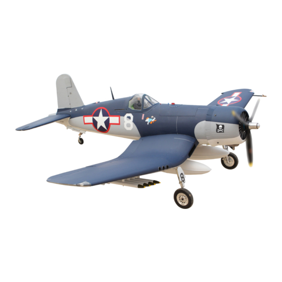
Specifications:
Wingspan--------------- 87 in--------------------- 221 cm.
Wing area--------------- 2562.5 sq.ins---------- 165 sq.dm.
Weight------------------- 30.9 lbs----------------- 14 kg.
Length------------------- 66.9 in------------------ 170 cm.
Engine------------------- 60cc.
Motor-------------------- 360/6000watt/ESC 200A/Lipo 12s.
Radio--------------------- 12 channels with 12 servos.
1
Advertisement
Table of Contents

Related Manuals for Seagull Models SEA361


Summary of Contents for Seagull Models SEA361
- Page 1 Code : SEA361 ASSEMBLY MANUAL Specifications: Wingspan--------------- 87 in--------------------- 221 cm. Wing area--------------- 2562.5 sq.ins---------- 165 sq.dm. Weight------------------- 30.9 lbs----------------- 14 kg. Length------------------- 66.9 in------------------ 170 cm. Engine------------------- 60cc. Motor-------------------- 360/6000watt/ESC 200A/Lipo 12s. Radio--------------------- 12 channels with 12 servos.
-
Page 2: Kit Contents
Instruction Manual. Giant Scale F4U Goodyear FG-1D 60cc ARF 87” Limited Edition. INTRODUCTION Thank you for choosing the ARTF Giant Scale F4U Goodyear FG-1D 60cc ARF 87” Limited Edition by SG MODELS . The was de- Giant Scale F4U Goodyear FG-1D 60cc ARF 87” Limited Edition signed with the intermediate/advanced sport flyer in mind. -
Page 3: Additional Items Required
WING TIP BULBS KIT CONTENTS SEA361 Giant Scale F4U Goodyear Please see below pictures. FG-1D 60cc ARF 87” Limited Edition. 1. Fuselage 2. Wing set (3 pcs) 3. Tail set (2 pcs) 4. Canopy 5. Cowling 6. Wing tube 7. Fuel tank 8. - Page 4 Instruction Manual. Giant Scale F4U Goodyear FG-1D 60cc ARF 87” Limited Edition. C/A glue Epoxy INSTALL THE AILERONS CONTROL HORN Fiberglass control horn...
-
Page 5: Installing The Aileron Servos
INSTALLING THE AILERON SERVOS Epoxy Recommended Servo Spec Torque. Epoxy 378 oz-in (27.3 kg-cm) @ 6.0V 467 oz-in (33.7 kg-cm) @ 7.4V Ailerons control horn Because the size of servos differ, you may need to adjust the size of the precut opening in the mount. - Page 6 Instruction Manual. Giant Scale F4U Goodyear FG-1D 60cc ARF 87” Limited Edition. Secure the servo to the aileron hatch using a proper driver and the screws provided with the servo. Use drill bit in a pin vise to drill the mouting holes in the blocks.
-
Page 7: Aileron Pushrod Installation
AILERON PUSHROD INSTALLATION Please see pictures below. 80mm M3 lock nut M3 clevis Set the aileron hatch in place and use a Phillips screw driver to install it with four wood screws. M3x10mm... - Page 8 Instruction Manual. Giant Scale F4U Goodyear FG-1D 60cc ARF 87” Limited Edition. Attach the flap linkage to the control INSTALLING THE FLAP PUSHROD horn. Slide the clevis retainer over the forks of the clevis. Please see pictures below. 120mm M3 clevis Attach the clevis to the flap servo arm.
- Page 9 Adjust the linkage so the flap is in the Set the flap control at the transmitter to mid-flap position. It may take a few tries the down flap position. Adjust the flap to properly adjust the linkage. travel at the transmitter until it matches the control throws listed in this manual.
- Page 10 Instruction Manual. Giant Scale F4U Goodyear FG-1D 60cc ARF 87” Limited Edition. 75mm M3 clevis M3 lock nut...
- Page 11 Install the gear door, please see the picture below. 18mm 100mm...
- Page 12 Instruction Manual. Giant Scale F4U Goodyear FG-1D 60cc ARF 87” Limited Edition. Install the gear door servo into the wing INSTALLING ROBART cover as shown below in these illustrated LANDING GEAR steps. Retractable landing gear are not included. Please study images below for proper instal- lation.
- Page 13 M4x15mm Install Main Retractable Landing Gear. Install aluminum pedestal, please see the picture below.
- Page 14 Instruction Manual. Giant Scale F4U Goodyear FG-1D 60cc ARF 87” Limited Edition. M4x12mm M3x6mm Install aluminum pieces into the landing Install the fork cover. gear struts as shown below.
- Page 15 1.5mm 1.5mm M2x10mm M2x10mm...
- Page 16 Instruction Manual. Giant Scale F4U Goodyear FG-1D 60cc ARF 87” Limited Edition. 2x6mm...
- Page 17 Epoxy M3x10mm...
- Page 18 Instruction Manual. Giant Scale F4U Goodyear FG-1D 60cc ARF 87” Limited Edition. Main Wheel installation.
- Page 19 INSTALLING RETRACTABLE LANDING GEAR - Locate items necessary to install Sprin Landing Gear. You use this fork set JP ER-150 100 Retracts Rotating 90...
- Page 20 Instruction Manual. Giant Scale F4U Goodyear FG-1D 60cc ARF 87” Limited Edition. M4x12mm M4x15mm...
- Page 21 M2x10mm M3x4mm...
- Page 22 Instruction Manual. Giant Scale F4U Goodyear FG-1D 60cc ARF 87” Limited Edition. M3x6mm...
- Page 23 M3x4mm ROCKETS INSTALLATION Please study images below. M4x5mm...
- Page 24 Instruction Manual. Giant Scale F4U Goodyear FG-1D 60cc ARF 87” Limited Edition. Epoxy...
- Page 25 DROP TANK/BOMB INSTALLATION Please study images below.
- Page 26 Instruction Manual. Giant Scale F4U Goodyear FG-1D 60cc ARF 87” Limited Edition. 10mm Install drop tank/bomb releases as shown. You should buy this to use. E-flite - EFLA405 ; E-flite - EFLA406 M2x6mm...
- Page 27 M4x70mm...
- Page 28 Instruction Manual. Giant Scale F4U Goodyear FG-1D 60cc ARF 87” Limited Edition. 2.5x10mm Install the drop tank, please see the picture below.
-
Page 29: Wing Assembly
WING ASSEMBLY Please study images below. - Page 30 Instruction Manual. Giant Scale F4U Goodyear FG-1D 60cc ARF 87” Limited Edition. M6x30mm M6x30mm...
-
Page 31: Installing The Fuselage Servos
Assembly the plastic decor cover at the bottom of center wing. INSTALLING THE FUSELAGE SERVOS Because the size of servos differ, you may need to adjust the size of the precut opening in the mount. The notch in the sides of the mount allow the servo lead to pass through. - Page 32 Instruction Manual. Giant Scale F4U Goodyear FG-1D 60cc ARF 87” Limited Edition. THROTTLE SERVO ARM INSTALLING THE ENGINE SWITCH INSTALLATION Install adjustable servo connector on the servo arm and set aside for now. Switch Elevator servo arm INSTALLING THE STOPPER Rudder servo arm ASSEMBLY Using a modeling knife, carefully cut...
-
Page 33: Fuel Tank Installation
With the stopper assembly in place, the weighted pick-up should rest away from the rear of the tank and move freely inside the tank. The top of the vent tube should rest just below the top of the tank. It should not touch the top of the tank. -
Page 34: Mounting The Engine
Instruction Manual. Giant Scale F4U Goodyear FG-1D 60cc ARF 87” Limited Edition. Vent tube Fuel pick up tube Fuel fill tube Later you with connect the lines from the tank to the engine and muffler. The vent line will connect to the muffler and the line from the clunk to the carburetor. - Page 35 M5x80mm...
- Page 36 Instruction Manual. Giant Scale F4U Goodyear FG-1D 60cc ARF 87” Limited Edition. Ignition Modude Pushrod wire 190mm...
- Page 37 4x5mm...
- Page 38 Instruction Manual. Giant Scale F4U Goodyear FG-1D 60cc ARF 87” Limited Edition. Move the throttle stick to the closed position and move the carburetor to closed. Use a 4x5mm hex wrench to tighten the screw that secures the throttle pushrod wire.
- Page 40 Instruction Manual. Giant Scale F4U Goodyear FG-1D 60cc ARF 87” Limited Edition. Use a drill and drill bit to drill the holes for the cowl mounting screws. Make sure the cowl position is correct before drilling each hole. Install the muffler onto the engine and make the cutout in the cowl for muffler clearance.
- Page 41 ELECTRIC POWER CONVERSION Locate the items neccessary to install the electric power conversion included with your model. Recommend the items necessary to install the electric power conversion parts included with your model. - Motor: 360/6000watt - ESC: 200A - 12S Lipo...
- Page 42 Instruction Manual. Giant Scale F4U Goodyear FG-1D 60cc ARF 87” Limited Edition. Attach the electric motor box to the fire- wall centered with the cross lines drawn on the electric motor box and firewall. Using M6x25mm to secure the motor box to the firewall.
- Page 43 Blind nut Attach the motor mount to the front of the 5.2mm electric motor box using four 4mm blind nut, four M6x25mm hex head bolts to se- cure the motor. Please see picture shown. M5x25mm Then, use 5.2mm drill bit to enlarge the holes on the electric motor box.
- Page 44 Instruction Manual. Giant Scale F4U Goodyear FG-1D 60cc ARF 87” Limited Edition. Speed control Attach the speed control to the side of the motor box using two-sided tape and tie wraps. Connect the appropriate leads from the speed control to the mo- tor.
- Page 45 The propeller should not touch any part of the cowling. If it does, check and adjust engine mounting/cowl spacing as needed to where the propeller will not come in contact with the cowling. INSTALL LED BULB FOR FUSELAGE Please study images below.
- Page 46 Instruction Manual. Giant Scale F4U Goodyear FG-1D 60cc ARF 87” Limited Edition. Epoxy...
- Page 47 Epoxy Epoxy INSTALL ELEVATOR CONTROL HORN Install the elevator control horn using the same method as same as the flap control horns. Epoxy...
- Page 48 Instruction Manual. Giant Scale F4U Goodyear FG-1D 60cc ARF 87” Limited Edition. Epoxy Epoxy INSTALL RUDDER CONTROL HORN Install the rudder control horn using the same method as the aileron control horns. Fiberglass control horn...
- Page 49 INSTALLING HORIZONTAL STABLLIZER Use Epoxy to glue the Horizontal Stabilizer to the fuselage. Epoxy Epoxy Epoxy Fiberglass control horn...
-
Page 50: Installation
Instruction Manual. Giant Scale F4U Goodyear FG-1D 60cc ARF 87” Limited Edition. Assemble the elevator and rudder pushrods as shown in images below. 995mm Check alignment Ausrichtung überprüfen M3 clevis Ball Link Elevator Pushrod ELEVATOR PUSHROD HORN M3 clevis INSTALLATION Install the elevator control horn us- ing the same method as with the aileron control horns. -
Page 51: Rudder Cable Installation
RUDDER CABLE INSTALLATION Study images below to install pull-pull cable set. 875mm MOUNTING THE TAIL GEAR ROBART M3 clevis Ball Link Gather tail gear components as shown below for installation. Robart ELECTRIC TAIL GEAR RH OFFSET 160RWCE... - Page 52 Instruction Manual. Giant Scale F4U Goodyear FG-1D 60cc ARF 87” Limited Edition. M3x20mm...
- Page 53 3x4mm M3x15mm M3x15mm...
- Page 54 Instruction Manual. Giant Scale F4U Goodyear FG-1D 60cc ARF 87” Limited Edition. M4x10mm...
- Page 56 Instruction Manual. Giant Scale F4U Goodyear FG-1D 60cc ARF 87” Limited Edition. C/A glue...
- Page 58 Instruction Manual. Giant Scale F4U Goodyear FG-1D 60cc ARF 87” Limited Edition. MOUNTING THE TAIL GEAR RETRACTABLE Locate items necessary to install.
- Page 59 Install the plastic snap to the fuselage behind the tail underside, please see the picture below. C/A glue...
- Page 60 Instruction Manual. Giant Scale F4U Goodyear FG-1D 60cc ARF 87” Limited Edition. Battery INSTALLING BATTERY - RECEIVER M3x10mm Plug the servo leads and the switch lead into the receiver. Plug the battery pack lead into the switch also. Wrap the receiver and battery pack in the protective foam rubber to protect them from vibration.
-
Page 61: Cockpit Installation
COCKPIT INSTALLATION M6x60mm Locate all cockpit components as shown below. M6x60mm... - Page 62 Instruction Manual. Giant Scale F4U Goodyear FG-1D 60cc ARF 87” Limited Edition. 10mm...
- Page 63 C/A glue C/A glue...
- Page 64 Instruction Manual. Giant Scale F4U Goodyear FG-1D 60cc ARF 87” Limited Edition. C/A glue C/A glue C/A glue...
- Page 65 C/A glue C/A glue...
- Page 66 Instruction Manual. Giant Scale F4U Goodyear FG-1D 60cc ARF 87” Limited Edition. C/A glue C/A glue...
- Page 67 3.2mm C/A glue...
- Page 68 Instruction Manual. Giant Scale F4U Goodyear FG-1D 60cc ARF 87” Limited Edition. C/A glue C/A glue C/A glue C/A glue...
- Page 69 INSTALL MAIN FUEL TANK COVER Please study images below.
-
Page 70: Installing Antennas
Instruction Manual. Giant Scale F4U Goodyear FG-1D 60cc ARF 87” Limited Edition. INSTALLING ANTENNAS INSTALL MACHINE GUN Please study images below. Antennas feature banana plugs for easy installation and removal. - Page 71 C/A glue C/A glue INSTALL PITOT TUBE (PROT WING) Please study images below.
- Page 72 Instruction Manual. Giant Scale F4U Goodyear FG-1D 60cc ARF 87” Limited Edition. Mount the wing to the fuselage. Place a piece of masking tape on the top of each wing 145mm back from the leading edge at the wing root. With the model inverted, place your fingers on the masking tape and carefully lift the plane.
- Page 73 CG-120mm...
-
Page 74: Control Throws
Instruction Manual. Giant Scale F4U Goodyear FG-1D 60cc ARF 87” Limited Edition. CONTROL THROWS Ailerons: Rudder: High Rate : High Rate : Up : 30 mm Right : 35 mm Down : 30 mm Left : 35 mm Low Rate : Low Rate : Up : 25 mm Right : 30 mm... -
Page 75: Flight Preparation
FLIGHT PREPARATION PREFLIGHT CHECK Check the operation and direction of the 1) Completely charge your transmit- elevator, rudder, ailerons and throttle. ter and receiver batteries before your first day of flying. A) Plug in your radio system per the 2) Check every bolt and every glue joint manufacturer’s instructions and turn eve- iant Scale F4U Goodyear FG-1D in the... - Page 76 Instruction Manual. Giant Scale F4U Goodyear FG-1D 60cc ARF 87” Limited Edition. If you have any queries, or are interested in our products, please feel free to contact us Factory : 12/101A - Hamlet 4 - Le Van Khuong Street - Dong Thanh Ward - Hoc Mon District - Ho Chi Minh City - Viet Nam.
Need help?
Do you have a question about the SEA361 and is the answer not in the manual?
Questions and answers