Table of Contents
Advertisement
Quick Links
Advertisement
Table of Contents

Related Manuals for Renishaw HS20


Summary of Contents for Renishaw HS20
- Page 1 Installation and user’s guide M-8003-3192-05-A HS20 installation guide...
- Page 2 Renishaw system, the environment. This equipment generates, uses and can motion system remains safe.
- Page 3 Packaging Packaging Material 94/62/EC 94/62/EC components code number Renishaw plc declares that the HS20 laser encoder Outer box Cardboard - 70% complies with the applicable directives, standards and recycled material regulations. Inserts Cardboard HS20 Laser measurement system relevant patents and...
-
Page 5: Table Of Contents
Page: 14 Mounting options for the HS20 laser head Page: 14 HS20 external dimensions and mounting holes Page: 16 HS20 mounting plate external dimensions and mounting holes Page: 17 HS20 alignment plate Page: 17 HS20 alignment plate adjustments Page: 18... - Page 6 Digital quadrature update rate Page: 37 Parity Page: 37 Error signal monitoring Page: 38 Status lines Page: 38 Section 4 - HS20 laser beam alignment Page: 39 HS20 laser beam alignment Page: 40 LS06 operation Page: 40 Alignment procedure Page: 41...
-
Page 7: Section 1 - Operation Overview Page
HS20 beam protection ducting Alignment plate kit Alignment tool kit LS06 laser steerer Reference mark switch assembly RCU compensator Storage and handling Machine requirements summary HS20 laser with long range linear optics HS20 laser with standard linear optics Typical HS20 installation... -
Page 8: Introduction Page
It is essential that the system is installed in accordance with the instructions in the installation manuals and it is the responsibility of the system integrator to ensure that, in the event of a failure of any part of the Renishaw laser system, the motion system remains safe. -
Page 9: Secondary Fault Protection Measures Page
It is the responsibility of the system integrator to ensure that in the event of a failure of any part of the Renishaw Laser System that the motion system remains safe. In the case of motion systems with powers or speeds capable of causing injury, secondary protection measures must be included in the design. -
Page 10: Operation Overview Page
Operation overview The HS20 laser head can be incorporated into the position control loop of any motion-control system that can be configured to accept digital or analogue quadrature format encoder signals. The laser head can be fitted as a direct replacement for linear encoder systems both in OEM and retrofit applications. - Page 11 Please refer to the HS20 beam protection ducting installation manual (M-8003-5184) for further details about kit contents, part numbers ordering and installation.
- Page 12 Part No: A-8003-2898 The laser steering mechanism or ‘beam steerer’ is an alignment aid for the HS20 laser scale. The device allows easy adjustment of both the pitch and yaw of the laser beam. and can greatly simplify system alignment.
-
Page 13: Storage And Handling Page
• The machine controller must accept digital encoder feedback inputs of RS485/422 format differential AquadB or analogue sin/cos (1 Vpp). • The straightness of travel of any axis to which HS20 is to be fitted must be within ±0.5 mm to maintain beam alignment. -
Page 14: Hs20 Laser With Long Range Linear Optics Page
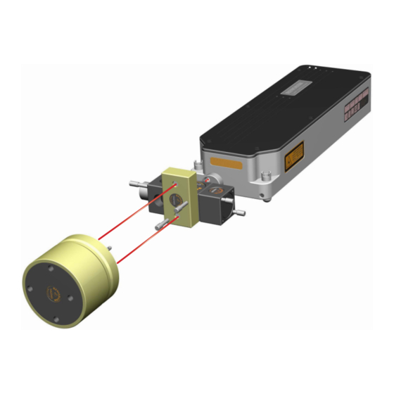
LS06 beam steerer Interferometer assembly (long range) Measurement retroreflector (long range) Figure 1 - HS20 with long range linear optics HS20 laser with standard linear optic LS06 beam steerer Interferometer assembly Measurement retroreflector Figure 2 - HS20 with standard linear optics... -
Page 15: Typical Hs20 Installation Page
Typical HS20 installation Figure 3 - Typical HS20 installation... -
Page 16: Section 2 - Mechanical Installation Page
Space requirements for the HS20 Golden rules of mechanical installation Mounting options for the HS20 laser head HS20 external dimensions and mounting holes HS20 mounting plate external dimensions and mounting holes HS20 alignment plate HS20 alignment plate adjustments Measurement retroflector mounting detail... -
Page 17: Space Requirements For The Hs20
Space requirements for the HS20 Before mechanical installation of the HS20 can be performed a mounting location must be decided. The position should be chosen by consideration of the following: Clearance required to adjust Minimum 250 mm (10 in) above the HS20 laser head... -
Page 18: Golden Rules Of Mechanical Installation. Page
HS20. Both options assume that the HS20 is mounted on the HS20 alignment plate. 1. Mounting directly to the machine rail with the HS20 laser beam parallel to the axis travel. Figure 5 - Direct mounting onto machine rail... - Page 19 Under these conditions it is strongly recommended that the Renishaw alignment plate is used since it has been designed to accommodate the small expansion of the HS20 laser during preheat without disturbing beam alignment.
-
Page 20: Hs20 External Dimensions And Mounting Holes Page
HS20 external dimensions and mounting holes This section details the key external dimensions along with the locations of mounting holes. (All dimensions are in mm) 25.5 16.5 Figure 7 - Key dimensions for HS20 laser head... -
Page 21: Hs20 Mounting Plate External Dimensions And Mounting Holes Page
Figure 8 - HS20 alignment plate dimensions HS20 alignment plate The HS20 alignment plate, in combination with the HS20’s adjustment feet, provides both translation and rotation in both vertical and horizontal planes, in a manner that is stable and controllable. The plate also provides an adjustable mount for the optical components, allowing translation and rotation in vertical and horizontal planes. -
Page 22: Hs20 Alignment Plate Adjustments Page
HS20 alignment plate adjustments : Anti-clockwise rotation : Clockwise rotation Figure 10 - Alignment plate adjustments... -
Page 23: Measurement Retroreflector Mounting Detail Page
Measurement retroreflector mounting detail Dimensions of the measurement retroreflectors used in both the standard linear measurement kit, and the long range measurement kits are detailed in figure 11. (All Dimensions are in mm) Figure 11 - Standard retroreflector outline drawing 4 HOLES TAPPED M8 X 6 DEEP Ø84... -
Page 24: Beam Position Relative To The Laser, Optics And Ducting Page
Beam position relative to the laser, optics and ducting All Dimensions are in mm and all positions are relative to the centre of the beam. In this example the HS20 laser head feet are set a nominal 15 mm from the base. 20.7 12.2... -
Page 25: Beam Protection Ducting Page
For full details please refer to the HS20 beam protection ducting manual, a summary is given below. The HS20 beam protection ducting system is based upon a standard extrusion supplied in 3 m lengths. -
Page 26: Ls06 Laser Steerer Page
The laser steerer is mounted onto the side of the interferometer nearest to the HS20 laser head using the clamp screws provided (see figure 15). When installing ensure that the two adjustment levers on the laser steerer are accessible and approximately in mid-position. -
Page 27: Reference Mark Switch Bracket And Actuating Cam Page
The reference mark switch is shown in figure 17 with fixing centres given. One reference mark switch is required for each axis using a HS20 laser head. The mount for the actuating cam must allow the position of the cam to be adjusted so that simultaneous switch operation can be achieved on split axis machines. -
Page 28: Mounting The Hs20 Laser Onto A Machine Page
Fitting the baseplate to the machine Information related to the specific dimensions and mounting hole locations can be found within the under the headings HS20 external dimensions and mounting holes and Mounting plate external dimensions and mounting holes within this section. - Page 29 Whilst maintaining the pillar orientation, tighten the cap head screw Fitting the HS20 laser 1. Fit the three adjustable feet to the HS20 laser head, setting them mid-way along their threaded section to allow full adjustment in both directions. as shown in figure 21.
-
Page 30: Protecting The Hs20 Laser Head Page
Protecting the HS20 laser head In most cases the laser head will have some form of primary protection, such as the machine way covers. If this is not the case then it will be necessary to protect the laser head from physical impact and contamination by using an enclosure that covers the laser and alignment plate assembly. -
Page 31: Section 3 - Electrical Installation And System Configuration Page
System grounding (earthing) HS20 cables and connectors Cable preparation HS20 interface connector 24V DC input connector HS20 diagnostic connector Powering down and disconnecting the HS20 Power requirements Output quadrature format Analogue quadrature -1v analogue interface Signal strength HS20 configuration Configuration switch function... -
Page 32: General Page
Several factors in the overall electrical characteristic of the installation will be relevant. • The machine structure should be well bonded at the same potential. • The HS20 laser head should be connected to earth via the 24V power input on the rear of the unit. - Page 33 Six pair, 24 AWG low capacitance ‘datalene’ cable used for: - Connections from HS20 to RCU10. Note: Belden 8166 cannot be used to carry 24V DC power to an HS20 laser head over distances greater than 10m (30ft) due to voltage drop. In this case Belden 9874 may be used but does have inferior screening.
-
Page 34: Hs20 Interface Connector Page
HS20 interface connector Figure 26 shows the pin out of the HS20 interface connector. It also shows the corresponding RCU pin connections for applications involving the RCU compensator. HS20 16 way 15 way Pair Signal name Comments circular D-Type number... -
Page 35: Dc Input Connector Page
Case (screen) Case (screen) Figure 27 - HS20 24V DC input connector HS20 diagnostic connector The pin out of the HS20 connector is as follows. HS20 diagnostic connector (9 way circular) Signal name Comments 0 to 1 V DC output representing 0 to Beam strength 100% return signal strength. -
Page 36: Powering Down And Disconnecting The Hs20
Powering down and disconnecting the HS20 To disconnect power to the HS20, first turn off the 24 V DC power supply, then unplug the HS20 interface connectors or disconnect the 24 V input connector. Ensure that the connectors on the rear of the HS20 are accessible by the operator. - Page 37 Depending on the type of quadrature required (analogue / digital), the way in which the signal strength is measured may vary. There are two methods of reading the signal strength from the HS20 as shown below: • Digital signal strength output - The digital representation of the signal strength is also available through the diagnostics connector in an RS485 format which can be connected to the RCU10 and a live signal strength viewed within the RCU-CS software.
- Page 38 For example, if the output resolution from the HS20 system is set to double that of the controller input, the axis may move twice as far and twice as fast as expected.
- Page 39 Configuration switch function Switch Function Notes No Function Should be set to OFF Quadrature Hysteresis ON = Disabled OFF = Enabled Quadrature Resolution see information later in this section Quadrature Resolution see information later in this section Quadrature Clock Frequency see information later in this section Quadrature Clock Frequency see information later in this section...
- Page 40 Quadrature resolution selection The quadrature resolution function can be selected using DIP switches 3 and 4. Four output resolutions are available as detailed below. Switch 3 Switch 4 Quadrature resolution (nominal) µm 0.6329905770 0.3164952885 0.1582476443 0.07912382213 Figure 34 - Quadrature edge to edge resolution selection NOTE: Resolution is the edge to edge separation of the digital quadrature signals Quadrature edge to edge separation parameters for consideration:...
- Page 41 WARNING: The controller must have an input bandwidth which is at least 25% greater than the update rate of the HS20 when using digital quadrature. If this update rate is set too low (below the count rate), the system will flag an overspeed error. If the update rate is set too high for the controller input bandwidth, the controller may miss some of the incoming pulses, resulting in a loss of feedback integrity.
- Page 42 24V DC and 0V and are active low. When the lines are unasserted (i.e. at 24V) the HS20 laser head sources 12mA and when the lines are asserted (i.e. at 0V) the HS20 laser head can sink up to 600mA. A detailed explanation of each of the status lines is shown below. The status lines should be monitored so that suitable status messages can be displayed on the controller’s display .
- Page 43 Section 4 - HS20 laser beam alignment Contained in this section HS20 laser beam alignment Alignment procedure...
- Page 44 This manual describes a simple method using the HS20 alignment plate. It is recommended that the HS20 laser head is aligned using the alignment plate for coarse alignment of the beam along the axis. Then using an LS06 Beam Steerer (A-8003-2898) to fine tune the laser alignment.
- Page 45 For information relating to mounting the HS20 onto the machine then refer to Section 2: Mechanical Installation. Note: It is recommended that when adjusting the locking screws on the alignment plate that there is no slack, as this can cause further movement when finally tightened.
- Page 46 3. Move the axis so the moving optic is a close as possible to the laser and interferometer. Place the alignment target onto the retroreflector. Translation adjustment should be made to the laser to ensure the laser beam hits the correct area of the target.
- Page 47 It may be easier to do this using the LS06 beam steerer. - Firstly tighten all the screws on the HS20 laser head and alignment plate. - Fit the LS06 beam steerer to the front of the interferometer. Take care not to move the optics.
- Page 48 ✓ Figure 48 - Correct return beam position 9. Tighten all locking screws (including locking screws for the LS06 steerer levers) and then recheck alignment / signal strength all the way down the axis (if not completed in previous step).
- Page 49 Laser power fail test Laser unstable test Beam low test Beam block test Overspeed test Quadrature check (direction and resolution) Switching machine control to HS20 feedback Machine under HS20 feedback testing Objectives Status line verification HS20 reset from machine control Machine home operation...
- Page 50 Reset input signal The HS20 laser head also requires one control line input. The function of this line is to reset the HS20 laser head in the event of an error. This line is active low and must be held at 24V (high) during normal operation.
- Page 51 HS20 diagnostic LEDs Two LED’s are fitted in the rear (opposite face to the laser beam aperture) of the HS20. When viewed from the rear of the HS20 with the connectors situated at the bottom they are termed laser status LED (left LED, LED closest to warning label) and signal condition LED (right LED).
- Page 52 The significance of the colour of the signal condition LED is as follows: Signal status LED LED Colour Significance Parity error FLASHING RED Beam block Beam low AMBER Beam low & overspeed FLASHING AMBER Good signal GREEN Good signal & overspeed FLASHING GREEN Figure 50 - Signal condition LED...
- Page 53 Laser power fail test Switch off the 24v power to the HS20 laser in turn and confirm that the controller flags “encoder error” on the associated axis and check that this error would cause the axis motion to be disabled.
- Page 54 If the sign correction is incorrect, then change the appropriate setting in the controller, or on the controller axis card, or swap AQUAD /AQUAD wires from HS20. If the distance moved does not match, adjust the HS20 resolution using the dip switches or adjust the controller settings.
- Page 55 2. Complete the integration by converting all axes concerned directly to Laser Feedback. 3. Move all axes and ensure that machine responds accordingly. Prior to the integration of the HS20 laser head, the machine will have been running on its primary feedback source (i.e. motor encoders or tape scale).
- Page 56 ‘encoder disconnect’ which detects the absence of feedback signals to the encoder inputs and similarly shuts down the drives. Repeat the HS20 laser head status line tests. In particular the operation of the beam block error must be confirmed to safely shut down the drives and apply safety brakes.
- Page 57 APPENDIX A – System specification HS20 laser head specification Laser type HeNe Class II Maximum output power from laser tube <1 mW Wavelength 632.8 nm Laser beam diameter 6 mm 12 mm centre to centre (outward and return beams) Vacuum wavelength accuracy ±0.1 ppm...
- Page 58 APPENDIX B - Maintenance The HS20 laser head will require very little in terms of routine maintenance, but the work that is required is primarily optical component cleaning. There are no user serviceable components inside the HS20 laser head Two forms of optical maintenance may be required during the lifetime of the HS20 laser head. This maintenance will either be to remove contamination from the optics or to re-establish optical alignment between the HS20 laser head and the optical elements which make up the linear measurement kit.
- Page 59 Renishaw. There are no user-serviceable parts inside the HS20. The only parts of the system that may require attention throughout their life are the exposed optics. If the system is not operated in a clean environment, surface contamination will accumulate on the optics over a period of time.
- Page 60 Reassemble the shutter onto the HS20 using one M3 x 10 Cap Head Screw and the brass M3 Crinkle Washer. Use Loctite 222 on the Cap Head Screw. Do not fully tighten the cap screw, instead adjust the screw to allow the shutter to rotate smoothly. Leave assembly 24 hours for Loctite 222 to fully cure.
- Page 61 Axis Name Serial No Axis 1 Axis 2 Axis 3 Axis 4 No of Axes Notes Installation Engineers Date Stage 1 - Pre HS20 Feedback Testing Test Details Notes Installation inspection Lasers, sensors & Pre-1 switches mounted? Pre-2 Safety...
- Page 62 Stage 1 - Pre HS20 feedback testing (continued) Test Details Axis Notes Pre-4 Laser Beam Power Fail Pre-5 Laser Unstable Pre-6 Beam-low Pre-7 Beam-block & reset test Pre-8 Overspeed Quadrature check Pre-9 (Direction & Resolution)
- Page 63 Stage 2 - Switching machine control to HS20 feedback Test Details Axis Notes Post-1 Integration procedure Stage 3 - Machine under HS20 feedback testing Test Details Axis Notes Status line verification Post-3 Axis 1 Status line verification Post-4...
- Page 64 It is essential that the system is installed in accordance with the instructions in the installation manuals and it is the responsibility of the system integrator to ensure that, in the event of a failure of any part of the Renishaw laser system, the motion system remains safe.
- Page 65 If the quadrature resolution is set incorrectly, the axis may move for distances and at speeds that are not expected. For example, if the output resolution from the Renishaw system is set to half that of the controller input, the axis may move twice as far and twice as fast as expected.
- Page 66 Important note: In the event of power loss from the HS20, tristated quad become inactive and the axis of motion must be stopped.
- Page 67 Once the system has been aligned the laser steering mechanism should be locked in position using the grub screws shown. The laser steering mechanism is mounted onto the side of the beam-splitter nearest to the HS20 laser as shown in figure E.1 using the clamp screws provided.
- Page 68 APPENDIX F – Glossary Bandwidth The maximum count frequency which may be applied to the controller/ counter input. In a quadrature signal, count rate is 4 × signal frequency. Beam splitter An optic which is used to split the two polarisation states of the laser beam into measurement and reference arms.
- Page 69 APPENDIX G – HS20 laser head labels The following safety labels are attached to the HS20 laser head Laser Interferometer Laser Interferometer Laser Interferometer Laser Interferometer WARNING WARNING DISCONNECT FROM POWER WARNING DISCONNECT FROM POWER BEFORE REMOVING COVER DISCONNECT FROM POWER...
- Page 72 © 2011-2019 Renishaw plc. All rights reserved. Renishaw reserves the right to change specifications without notice. RENISHAW and the probe symbol used in the RENISHAW logo are registered trade marks of Renishaw plc in the United Kingdom and other countries. Part no. M-8003-3192-05-A apply innovation and names and designations of other Renishaw products and technologies are trade marks of Renishaw plc or its subsidiaries.
Need help?
Do you have a question about the HS20 and is the answer not in the manual?
Questions and answers