
Related Manuals for Extron electronics SF 3C LP


Summary of Contents for Extron electronics SF 3C LP
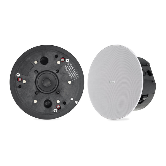
- Page 1 User Guide Speakers SF 3C LP and SF 3CT LP SoundField XD 3" Full-Range Ceiling Speakers with 4" Low Profile Composite Back Can 68-2224-01 Rev. D 09 20...
- Page 3 Copyright © 2016-2020 Extron. All rights reserved. www.extron.com All trademarks mentioned are the property of their respective owners.. Trademarks All trademarks mentioned in this guide are the properties of their respective owners. The following registered trademarks ( ® ), registered service marks ( ), and trademarks ( ) are the property of RGB Systems, Inc.
- Page 4 FCC Class A Notice This equipment has been tested and found to comply with the limits for a Class A digital device, pursuant to part 15 of the FCC rules. The Class A limits provide reasonable protection against harmful interference when the equipment is operated in a commercial environment. This equipment generates, uses, and can radiate radio frequency energy and, if not installed and used in accordance with the instruction manual, may cause harmful interference to radio communications.
-
Page 5: Table Of Contents
Ceiling ............. 30 Painting the Speaker Grille ........ 39 Troubleshooting: Signal Test Points ....40 Testing Source Signal (All Configurations) ..40 Testing the Impedance (Loop-Through Configuration Only) ........40 SF 3C LP and SF 3CT LP User Guide • Contents... - Page 6 SF 3C LP and SF 3CT LP User Guide • Contents...
-
Page 7: Introduction
SF 3CT LP feature a thin-edged bezel and a magnetically attached grille. The SF 3C LP supports 8 ohm operation. The SF 3CT LP supports 70 V, 100 V, and 8 ohm direct operation. The SF 3CT LP has a 6-position rotary switch for selecting the various power taps for 70V, 100V, or 8 ohms. - Page 8 Thin bezel and magnetically attached grille • UL 2043 plenum-rated enclosure • UL 1480 listed for safety Dimensional and weight savings — reduces overall storage and shipping costs • SF 3C LP and SF 3CT LP User Guide • Introduction...
-
Page 9: Application Example
480p 720p 1080i 1080p LAPTOP SELECT D I R E C T V HDMI EBP 100 TUNER VOLUME Tuner eBUS Button Panel MUTE 2-Gang Extron Figure 1. Typical SF 3CT LP Application SF 3C LP and SF 3CT LP User Guide • Introduction... -
Page 10: Installation
• If using secondary support cables, the installer provides the cables. Installation Configurations The SF 3C LP and SF 3CT LP can be configured for the following ceiling types: • Suspended ceiling: The following sections describe speaker installation procedures for suspended ceilings. -
Page 11: Installing The Speaker System In A Suspended Ceiling - Single Installer
Fit the tab of one end into the slot of the other end. Open the V-rail until it locks together. iii. Repeat this procedure for the other V-rail. Figure 2. Assembling the V-rails SF 3C LP and SF 3CT LP User Guide • Installation... - Page 12 C-ring V-rail Figure 3. Positioning the C-ring assembly on the V-rails Secure the C-ring to the V-rails using two screws. Route the speaker wires through the ceiling tile hole. SF 3C LP and SF 3CT LP User Guide • Installation...
- Page 13 1.5 inches, the locking arm inserts must be removed. To remove the inserts: Using a screwdriver, rotate the locking arm so that the insert can be accessed. Figure 4. Accessing the locking arm insert SF 3C LP and SF 3CT LP User Guide • Installation...
- Page 14 Loosen the two side cable conduit access plate screws and remove the plate before wiring the speaker. Cable/Conduit Access Plate Screws (2) Cable Clamp Alternate Knockout Figure 6. Removing the Cable Conduit Access Plate SF 3C LP and SF 3CT LP User Guide • Installation...
- Page 15 Maximum Number of Wires per (Black) Connection Point Wire Gauge 12 AWG 16 AWG 18 AWG Power Amplifier Speaker 1 Figure 7. Attaching the Speaker Wires to the Connector SF 3C LP and SF 3CT LP User Guide • Installation...
- Page 16 à l’impédance minimum de l’amplificateur. Insert the captive screw plug into the four-pole receptacle of the speaker. Using a cable clamp on the cable conduit access plate: Figure 8. Using a Cable Clamp SF 3C LP and SF 3CT LP User Guide • Installation...
- Page 17 The side access wire opening can be useful in low profile installations. • The top access wire opening can be more convenient to use. Tighten the cable clamp if it was used. SF 3C LP and SF 3CT LP User Guide • Installation...
- Page 18 Stop Tightening when the Opti-Torque Indictor Ring Falls ATTENTION: • To avoid damaging the speaker, do not overtighten the three screws. • Pour éviter d’endommager l’enceinte, ne serrez pas trop les trois vis. SF 3C LP and SF 3CT LP User Guide • Installation...
- Page 19 Do not allow any slack in the secondary support line. • Ne laissez pas de mou au niveau du filin de sécurité secondaire. Replace the adjacent ceiling tile that was removed in step 4b on page 6. SF 3C LP and SF 3CT LP User Guide • Installation...
- Page 20 équivalent à une valeur inférieure à l’impédance minimum de l’amplificateur. 8Ω Adjust the Tap Selector Figure 13. Setting the Rotary Tap Selector Switch SF 3C LP and SF 3CT LP User Guide • Installation...
- Page 21 Figure 14. Installing the grille NOTE: Specific test points can be used to troubleshoot speaker system problems. Troubleshooting: Signal Test Points Should problems be encountered, please see on page 40. SF 3C LP and SF 3CT LP User Guide • Installation...
-
Page 22: Installing The Speaker System In A Suspended Ceiling - Division Of Labor
NOTE: The screws are not removeable. They loosen completely, but do not pull out. Figure 15. Unscrewing the Speaker Assembly from the Back Can SF 3C LP and SF 3CT LP User Guide • Installation... - Page 23 Using the provided cutout template, trace a circle around the cutout template. Cut out the circle traced on the ceiling tile. Replace the tile in the ceiling. SF 3C LP and SF 3CT LP User Guide • Installation...
- Page 24 Open the V-rail until it locks together. iii. Repeat this procedure for the other V-rail. Figure 17. Assembling the V-rails Remove a ceiling tile adjacent to the tile with the hole. SF 3C LP and SF 3CT LP User Guide • Installation...
- Page 25 C-ring V-rail Figure 18. Positioning the C-ring Assembly on the V-rails Secure the C-ring to the V-rails using two screws. Route the speaker wires through the ceiling tile hole. SF 3C LP and SF 3CT LP User Guide • Installation...
- Page 26 1.5 inches, the locking arm inserts must be removed. To remove the inserts: Using a screwdriver, rotate the locking arm so that the insert can be accessed. Figure 19. Accessing the locking arm insert SF 3C LP and SF 3CT LP User Guide • Installation...
- Page 27 Loosen the two side cable conduit access plate screws and remove the plate before wiring the back can. Cable/conduit access plate Screws (2) Cable clamp Alternate Knockout Figure 21. Removing the Cable Conduit Access Plate SF 3C LP and SF 3CT LP User Guide • Installation...
- Page 28 Maximum Number of Wires per (Black) Connection Point Wire Gauge 12 AWG 16 AWG 18 AWG Power Amplifier Speaker 1 Figure 22. Attaching the Speaker Wires to the Connector SF 3C LP and SF 3CT LP User Guide • Installation...
- Page 29 Figure 23. Using a Cable Clamp Using a conduit adapter on the cable conduit access plate: Flexible Conduit Adapter Flexible Conduit Ad d apter Figure 24. Using a Conduit Adapter SF 3C LP and SF 3CT LP User Guide • Installation...
- Page 30 Insert the back can through the bottom of the hole in the ceiling tile that was cut in step 6 on page 17 with the wires out of the way. Figure 25. Inserting the Speaker Back Can SF 3C LP and SF 3CT LP User Guide • Installation...
- Page 31 Stop Tightening when the Opti-Torque Indicator Ring Falls ATTENTION: • To avoid damaging the locking arms, do not overtighten the three screws. • Pour éviter d’endommager l’enceinte, ne serrez pas trop les trois vis. SF 3C LP and SF 3CT LP User Guide • Installation...
- Page 32 Do not allow any slack in the secondary support line. • Ne laissez pas de mou au niveau du filin de sécurité secondaire. Replace the adjacent ceiling tile that was removed in step 7b on page 18. SF 3C LP and SF 3CT LP User Guide • Installation...
- Page 33 Screwing the Speaker Assembly to the Back Can ATTENTION: • To avoid damaging the speaker, do not overtighten the three screws. • Pour éviter d’endommager l’enceinte, ne serrez pas trop les trois vis. SF 3C LP and SF 3CT LP User Guide • Installation...
- Page 34 équivalent à une valeur inférieure à l’impédance minimum de l’amplificateur. 8Ω Adjust the Tap Selector Figure 31. Setting the Rotary Tap Selector Switch SF 3C LP and SF 3CT LP User Guide • Installation...
- Page 35 Figure 32. Installing the Grille NOTE: Specific test points can be used to troubleshoot speaker system problems. Should problems be encountered, please see Troubleshooting: Signal Test Points on page 40. SF 3C LP and SF 3CT LP User Guide • Installation...
-
Page 36: Installing The Speaker System In A Hard Ceiling
Installing the Speaker System in a Hard Ceiling If you are installing the SF 3C LP or SF 3CT LP in a hard ceiling (having no ceiling tiles), with the ceiling structure in place, follow the steps below: Disconnect power Power down all attached devices before proceeding. - Page 37 1.5 inches, the locking arm inserts must be removed. To remove the inserts: Using a screwdriver, rotate the locking arm so that the insert can be accessed. Figure 34. Accessing the locking arm insert SF 3C LP and SF 3CT LP User Guide • Installation...
- Page 38 Loosen the two side cable conduit access plate screws and remove the plate before wiring the speaker. Cable/conduit access plate Screws (2) Cable clamp Alternate Knockout Figure 36. Removing the Cable Conduit Access Plate SF 3C LP and SF 3CT LP User Guide • Installation...
- Page 39 Number of Wires per Maximum (Black) Connection Point Wire Gauge 12 AWG 16 AWG 18 AWG Power Amplifier Speaker 1 Figure 37. Attaching the Speaker Wires to the Connector SF 3C LP and SF 3CT LP User Guide • Installation...
- Page 40 Figure 38. Using a Cable Clamp Using a conduit adapter on the cable conduit access plate: Flexible Conduit Adapter Flexible Conduit Ad d apter Figure 39. Using a Conduit Adapter SF 3C LP and SF 3CT LP User Guide • Installation...
- Page 41 Connecting a Secondary Support Line ATTENTION: • Do not allow any slack in the secondary support line. • Ne laissez pas de mou au niveau du filin de sécurité secondaire. SF 3C LP and SF 3CT LP User Guide • Installation...
- Page 42 Stop Tightening when the Opti-Torque Indicator Ring Falls ATTENTION: • To avoid damaging the speaker, do not overtighten the three screws. • Pour éviter d’endommager l’enceinte, ne serrez pas trop les trois vis. SF 3C LP and SF 3CT LP User Guide • Installation...
- Page 43 équivalent à une valeur inférieure à l’impédance minimum de l’amplificateur. 8Ω Adjust the Tap Selector Figure 43. Setting the Rotary Tap Selector Switch SF 3C LP and SF 3CT LP User Guide • Installation...
- Page 44 Figure 44. Installing the Grille NOTE: Specific test points can be used to troubleshoot speaker system problems. Should problems be encountered, please see Troubleshooting: Signal Test Points on page 40. SF 3C LP and SF 3CT LP User Guide • Installation...
-
Page 45: Painting The Speaker Grille
Be sure not to clog the grille holes. Wait for the paint to dry. Reattach the scrim to the back of the grille. Reattach the grille to the speaker. SF 3C LP and SF 3CT LP User Guide • Installation... -
Page 46: Troubleshooting: Signal Test Points
Red Wire (+) from Amplifier Amplifier To next speaker(s) Black Wire (-) from Amplifier Test Points Impedance Test Points Figure 47. Impedance Test Points — Loop-through Configuration SF 3C LP and SF 3CT LP User Guide • Installation... - Page 47 Extron Warranty Extron warrants this product against defects in materials and workmanship for a period of three years from the date of purchase. In the event of malfunction during the warranty period attributable directly to faulty workmanship and/ or materials, Extron will, at its option, repair or replace said products or components, to whatever extent it shall deem necessary to restore said product to proper operating condition, provided that it is returned within the warranty period, with proof of purchase and description of malfunction to: USA, Canada, South America,...
Need help?
Do you have a question about the SF 3C LP and is the answer not in the manual?
Questions and answers