
Subscribe to Our Youtube Channel
Related Manuals for Extron electronics SoundField XD SF 26CT LP


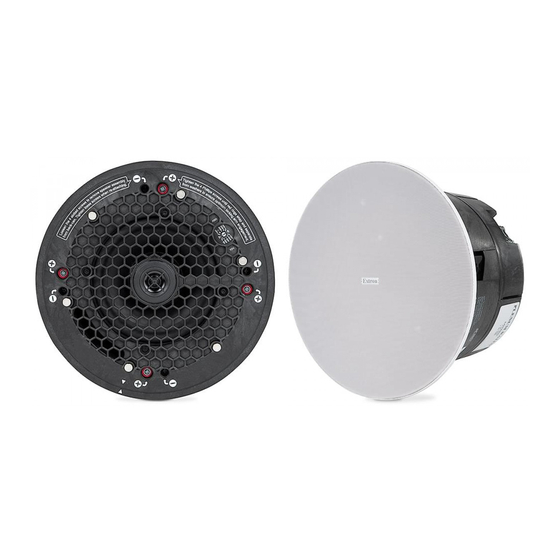
Summary of Contents for Extron electronics SoundField XD SF 26CT LP
- Page 1 User Guide Speakers SF 26CT LP SoundField XD Low-Profile 6.5" Two-Way Ceiling Speaker ® with 4.2" Composite Back Can 68-3443-01 Rev. A 06 20...
- Page 2 Safety Instructions Safety Instructions • English Istruzioni di sicurezza • Italiano AVVERTENZA: Il simbolo, , se usato sul prodotto, serve ad WARNING This symbol, , when used on the product, is intended to avvertire l’utente della presenza di tensione non isolata pericolosa alert the user of the presence of uninsulated dangerous voltage within all’interno del contenitore del prodotto che può...
- Page 3 Copyright © 2020 Extron Electronics. All rights reserved. Trademarks All trademarks mentioned in this guide are the properties of their respective owners. The following registered trademarks ( ® ), registered service marks ( ), and trademarks ( ) are the property of RGB Systems, Inc. or Terms of Use www.extron.com...
- Page 4 FCC Class A Notice This equipment has been tested and found to comply with the limits for a Class A digital device, pursuant to part 15 of the FCC rules. The Class A limits provide reasonable protection against harmful interference when the equipment is operated in a commercial environment. This equipment generates, uses, and can radiate radio frequency energy and, if not installed and used in accordance with the instruction manual, may cause harmful interference to radio communications.
-
Page 5: Table Of Contents
Contents ..............1 roduction Overview ............1 Features ............. 1 Application Example ........... 2 tallation in a Suspended Ceiling (Single ..............3 Installer) Installation Considerations ........3 Preparing the Installation Location ...... 3 Configuring the Speaker ........5 Mounting the Speaker ........9 allation in a Suspended Ceiling Inst .......... - Page 6 SF 26CT LP User Guide • Contents...
-
Page 7: Introduction
Introduction This section gives an overview of the Extron SF 26CT LP SoundField Low Profile XD 2-way ® speaker. Topics include: • Overview • Features • Application Example Overview The Extron SoundField® XD model SF 26CT LP is a low profile 6.5” (165 mm) two-way ceiling speaker featuring a 4.2”... -
Page 8: Application Example
Application Example The application diagram below shows one way to configure a system using the SF 26CT LP. Audio Extron Ethernet VoIP SF 26CT LP Full-Range Ceiling Speakers Conference Table Credenza Ethernet Extron Audio DMP 128 Plus C V Digital Matrix Processor Table 100-240V 0.7A MAX Microphones... -
Page 9: Installation In A Suspended Ceiling (Single Installer)
Installation in a Suspended Ceiling (Single Installer) If a single installer is installing the SF 26CT LP speaker system, follow the steps in this section. Topics in this section include: Installation Considerations • • Preparing the Installation Location • Configuring the Speaker •... - Page 10 Attach two V-rails and one C-ring across the tile above the hole cut in step 3, as shown below: Assemble two V-rail half sections as follows: fit the tab of one end into the slot of the other end, then open the V-rail until it locks together (see figure 2). Repeat this procedure for the other V-rail.
-
Page 11: Configuring The Speaker
Configuring the Speaker Configure the locking arms for thicker ceilings (optional). Four speaker locking arms are used to secure the speaker to ceiling tiles up to 2.25 inches (5.72 cm) thick. The locking arms are equipped with removable inserts to accommodate ceiling tiles up to 1.5 inches (3.81 cm) thick. - Page 12 Repeat steps a. and b. for the remaining three locking arms. Rotate all four locking arms back into the speaker. Configure the cable/conduit access plate and captive screw connector: Loosen the three access plate screws and remove the plate before wiring the speaker. Remove the Alternate terminal cover.
- Page 13 Attach the speaker wires to the captive screw connector depending on the configuration, using one of the three methods illustrated in figure 7. Wiring Multiple Speakers Using Loop-through When a chain of speakers is wired this way, disconnecting one speaker removes power from all downstream speakers. (Red) (Red) (Red)
- Page 14 Insert the captive screw plug into the four-pole receptacle of the speaker. Using a cable clamp on the access plate: • 4-pole Captive Screw Connector Figure 8. Using a Cable Clamp Using a conduit adapter on the access plate: • Flexible Conduit Adapter Figure 9.
-
Page 15: Mounting The Speaker
Mounting the Speaker The speaker can be Installed into rigid material (mineral tile, gypsum board, sheetrock, etc.) or soft material, such as fiberglass. Insert the speaker through the bottom of the hole in the ceiling tile that was cut in step 3 on page 3 (Preparing the Installation Location) with the wires out of the way. - Page 16 NOTE: Each of the four locking arm screws uses an Opti-Torque indicator ring. The indicator releases a red plastic ring onto the screwdriver once the screw is tightened to the correct torque. Stop tightening when this occurs to avoid overtightening the locking arms to the C-ring. Figure 11.
- Page 17 ATTENTION: Do not allow any slack in the secondary support line. • Ne laissez pas de mou au niveau du filin de sécurité secondaire. • Replace the adjacent ceiling tile that was removed in on page 4. step 4b Set the rotary tap selector switch to the appropriate setting using a small screwdriver. 8Ω...
- Page 18 Install the grille. Position the grille so that it covers the baffle of the speaker. Six small magnets secure the grille in place. Speaker Grille Figure 14. Installing the Grille NOTE: Specific test points can be used to troubleshoot speaker system problems. Should problems be encountered, please see Troubleshooting: Signal Test Points page 25.
-
Page 19: Installation In A Suspended Ceiling (Division Of Labor)
Installation in a Suspended Ceiling (Division of Labor) For a division of labor installation, follow the steps in this section. In a division of labor installation, low-voltage contractors first install the speaker back can enclosure (construction rough-in phase). After the back can has been installed, the second phase of the installation can begin by installing the speaker assembly to the back can. -
Page 20: Preparing The Installation Location
Carefully separate the speaker assembly from the back can, as shown in figure 16. NOTE: Disconnect the speaker wires from the speaker assembly before completely separating the speaker assembly from the back can. Figure 16. Separating the Speaker Assembly from the Back Can Repeat steps 1 and 2 for each speaker in the system and distribute the components to the appropriate installers. -
Page 21: Mounting The Speaker Enclosure
Mounting the Speaker Enclosure Mount the speaker back can enclosure. Insert the back can through the bottom of the hole in the ceiling tile that was cut with the wires out of the way. Figure 17. Inserting the Speaker Back Can Clamp the back can to the C-ring by using a Phillips screwdriver to tighten the four locking arms to the C-ring. - Page 22 Tightening the locking arms into rigid material: For rigid material use the Opti-Torque indicator ring as a tightening guide. ATTENTION: To avoid damaging the locking arms, do not overtighten the four screws. • Ne pas trop serrer les quatre vis pour éviter d’endommager les bras de •...
- Page 23 If required, attach a secondary support line. Connect a secondary support line to the support loop on the the back of the back can, as shown here. Anchor the end to suitable secure points within the solid and permanent building structure. Figure 20.
- Page 24 Using a flat head screwdriver, tighten the four screws that attach the speaker assembly to the back can. Figure 22. Attaching the Speaker to the Back Can Set the rotary tap selector switch to the appropriate setting using a small screwdriver (see figure 22).
- Page 25 Install the grille. Position the grille so that it covers the baffle of the speaker. Six small magnets secure the grille in place. Speaker Grille Figure 24. Installing the Grille NOTE: Specific test points can be used to troubleshoot speaker system problems. Should problems be encountered, please see Troubleshooting: Signal Test Points page 25.
-
Page 26: Installation In A Hard Ceiling
Installation in a Hard Ceiling To install the SF 26CT LP in a hard ceiling (having no ceiling tiles), with the ceiling structure in place, follow the steps in this section. Topics in this section include: • Preparing the Installation Location •... -
Page 27: Mounting The Speaker
Mounting the Speaker If required, attach a secondary support line. Connect a secondary support line to the support loop on the back of the speaker enclosure, as shown in figure 26. Anchor the end to suitable secure points within the solid and permanent building structure. - Page 28 NOTE: Each of the four locking arm screws uses an Opti-Torque indicator ring. The indicator releases a red plastic ring onto the screwdriver once the screw is tightened to the correct torque. Stop tightening when this occurs to avoid overtightening the locking arms to the C-ring. Figure 28.
- Page 29 ATTENTION: When setting the taps for a distributed (high impedance) system, do not tap • the system above the rated power of the amplifier. Lors de la mise en place des capteurs pour un système distribué (haute • impédance), n’exploitez pas le système au delà du niveau d’alimentation de l’amplificateur.
-
Page 30: Reference Information
Reference Information This section covers the following topics: • Painting the Speaker Grille • Troubleshooting: Signal Test Point Painting the Speaker Grille The speaker grille can be painted using spray paint. Ensure that the spray paint is plastic friendly and adheres to both metal and plastic. NOTE: Extron is not responsible for any alterations to the original paint. -
Page 31: Troubleshooting: Signal Test Points
Troubleshooting: Signal Test Points The following signal test points can be used to troubleshoot speaker system problems. Testing Source Signal (All Configurations) The source signal can be tested by connecting to the inner + (IN) and – (IN) terminals of the captive screw connector. - Page 32 Extron Electronics makes no further warranties either expressed or implied with respect to the product and its quality, performance, merchantability, or fitness for any particular use. In no event will Extron Electronics be liable for direct, indirect, or consequential damages resulting from any defect in this product even if Extron Electronics has been advised of such damage.
Need help?
Do you have a question about the SoundField XD SF 26CT LP and is the answer not in the manual?
Questions and answers