Table of Contents
Advertisement
Quick Links
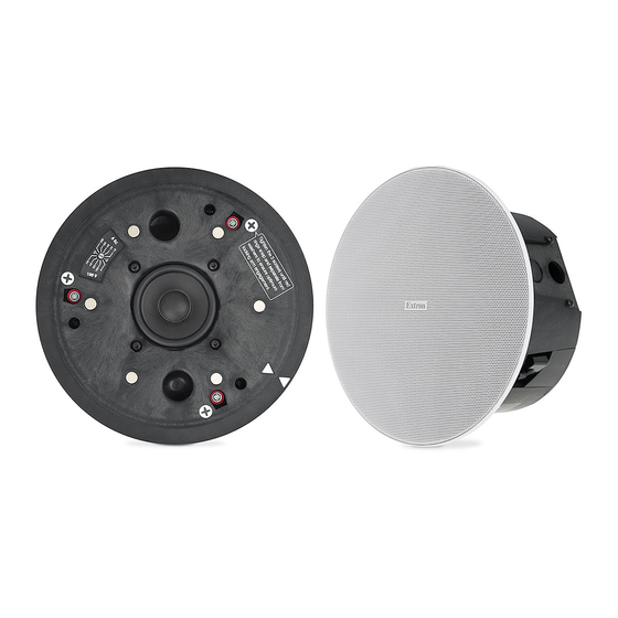
BCK SF 3CT LP and BCK SF 3C LP • Setup Guide
This setup guide contains installation information about the BCK SF 3CT LP, and BCK SF 3C LP. When fully assembled with
a DAK SF 3CT or DAK SF 3C they become a fully functioning SF 3CT LP or SF 3C LP Soundfield ® XD full range speaker,
respectively. These speakers can be installed by a single trade installation procedure or by a multitrade installation procedure (see
the SF 3C LP and SF 3CT LP User Guide, available at www.extron.com, for details). The entire assembly is plenum rated.
WARNING:
Potential risk of severe injury. Installation and service must be performed by authorized personnel only.
AVERTISSEMENT :
uniquement par un technicien qualifié..
NOTE: Installation of conduit and conduit adapters must conform to all applicable building codes and local ordinances.
Disconnect power from all devices.
1.
Verify the space where the system will be
2.
—
installed
Ensure that there is sufficient clearance
above the ceiling tile for the unit to be installed.
Cut a hole for the speaker
3.
cutout template to outline the hole to be cut in the
ceiling tile, as described below.
NOTE: For hard ceiling installations skip steps a
through e and use the cutout template to cut a
hole in the ceiling.
Remove the ceiling tile, and draw diagonal lines
a.
across it from opposite corners to locate its center.
Mark the intersection where the lines cross.
Position the center hole of the cutout template
b.
directly over the center of the tile, marked in
step 2a.
Trace a circle on the ceiling tile around the cutout
c.
template.
Cut out the circle traced in the ceiling tile.
d.
Replace the ceiling tile in the ceiling.
e.
Attach two V-rails and one C-ring acoss the tile and
4.
above the hole cut in step 3, as described below.
NOTE: For hard ceiling installations:
•
Fold one C-ring assembly in half and insert it
through the hole in the ceiling.
•
Unfold the C-ring and center it over the hole
with the flat side down.
•
V-rails are not needed.
Assemble two V-rail half sections so that they
a.
become one single piece by fitting the tab of one
end into the slot of the other end. Open the V-rail
until it locks together, as shown in the following
illustrations. Repeat this procedure for the other
V-rail.
Risque potentiel de blessure grave ou de mort. L'installation et l'entretien doivent être effectués
—
Use the provided
Remove a ceiling tile adjacent to the tile with the
b.
hole.
Place both assembled V-rails on the cut ceiling tile
c.
and position them equally on either side of the hole.
The ends of the V-rails go over the ceiling grid.
Position the C-ring assembly on the two V-rails so
d.
that the C-ring is centered over the hole.
V-rail
Secure the C-ring to the V-rails using two screws.
e.
Route the speaker wires through the ceiling tile hole.
5.
C-ring
1
Advertisement
Table of Contents

Related Manuals for Extron electronics BCK SF 3CT LP


Summary of Contents for Extron electronics BCK SF 3CT LP
- Page 1 BCK SF 3CT LP and BCK SF 3C LP • Setup Guide This setup guide contains installation information about the BCK SF 3CT LP, and BCK SF 3C LP. When fully assembled with a DAK SF 3CT or DAK SF 3C they become a fully functioning SF 3CT LP or SF 3C LP Soundfield ® XD full range speaker, respectively.
- Page 2 BCK SF 3CT LP and SF 3C LP • Setup Guide (Continued) With the cable/conduit access plate still Configure the locking arms for thicker ceilings attached to the speaker, place the tip of a (optional). flat-head screwdriver against the notch of the Three speaker locking arms, as shown below, are used knockout.
- Page 3 Power Amplifier Speaker 2 Speaker 1 Replace the cable/conduit access plate and tighten Wiring a Single Speaker Number of the two screws. Maximum (Red) Wires per Wire (Black) Connection NOTE: The cable/conduit access plate can be Gauge Point positioned in one of two ways depending on 12 AWG the application.
- Page 4 BCK SF 3CT LP and SF 3C LP • Setup Guide (Continued) NOTE: Each of the three locking arm screws ATTENTION: uses an Opti-Torque™ indicator. The • To avoid damaging or deforming soft indicator releases a red plastic ring onto...
Need help?
Do you have a question about the BCK SF 3CT LP and is the answer not in the manual?
Questions and answers