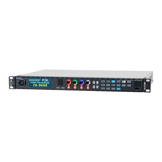
FOR-A FA-9600 Series Operation Manual
Frame synchronizer
Hide thumbs
Also See for FA-9600 Series:
- Operation manual (272 pages) ,
- Operation manuals (140 pages) ,
- Quick setup manual (2 pages)
Table of Contents
Advertisement
Quick Links
Advertisement
Table of Contents

Related Manuals for FOR-A FA-9600 Series


Summary of Contents for FOR-A FA-9600 Series
- Page 1 OPERATION MANUAL FA-9600 Frame Synchronizer FA-96PS FA-964K FA-96UDC FA-96AHDR/AHDR2 FA-96AES-UBL/-UBLC FA-96ANA-AUD FA-96MADI FA-96EX3G44-R FA-96EX12G06 FA-96SFPC4 FA-96GPI FA-96DB9-CBL FA-96DIN4-CBL Edition - Rev. 6 (Software Ver. 3.6 or higher)
- Page 2 Edition Revision History Edit. Rev. Date Description Section 2017/09/15 Supported 1080/59.94i, 1080/59.94p and 2160/59.94p. 2017/09/25 Supported multi-format video signals. Supported HDMI, etc. 2017/11/17 Added FA-96DIN4-CBL. Revised HDR related menus. 5-4 to 5-8 10-2-5 2017/12/22 Corrected GPI IN circuits. 3-3, 3-4 Revised Loss Mode description.
- Page 3 Precautions Important Safety Warnings [Power] Operate unit only at the specified supply voltage. Caution Disconnect the power cord via the power plug only. Do not pull on the cable portion. Do not place or drop heavy or sharp-edged objects on the power cord. A damaged cord can cause fire or electrical shock hazards.
- Page 4 [Circuitry Access] Do not remove covers, panels, casing, or access the circuitry with power applied to the unit. Turn the power off and disconnect the power cord prior to removal. Internal servicing / adjustment of unit should only be performed by qualified personnel. Do not touch any parts / circuitry with a high heat factor.
- Page 5 Upon Receipt FA-9600 units and their accessories are fully inspected and adjusted prior to shipment. Check your received items against the packing lists below. Check to ensure no damage has occurred during shipment. If damage has occurred, or items are missing, inform your supplier immediately. ◆...
- Page 6 Installing the AC Cord Retention Clip Secure the AC cord with the supplied ladder strap/retention clip assembly to prevent accidental removal from the unit. ◆ Installing the clip Wrap the retention clip around the AC cord (with the anchor of the ladder strap toward the unit).
-
Page 7: Table Of Contents
Table of Contents 1. Prior to Starting ...........................12 1-1. Overview ...........................12 1-2. Key Features ..........................12 1-3. Three MU Main Mode .......................13 1-4. Notice on Overheat Protection ....................13 1-5. Connection Example (Video Input / Output) ................14 1-5-1. 4K In / HD Out + HD In / HD Out ..................14 1-5-2. - Page 8 5-16. INPUT LINKAGE PROCESS (VIDEO) ...................48 5-17. INPUT LINKAGE PROCESS (AUDIO) ...................49 5-18. DYNAMIC RANGE GAIN CONTROL ..................49 5-19. OUTPUT SELECT ........................50 5-19-1. OUTPUT SELECT (Slot A) ....................50 5-19-2. 4K (UHD) SDI Interface ....................52 5-20. CONVERTER FORMAT (FA-96UDC) ..................54 5-20-1. Available Conversions on Converter 1 (FS1) ..............55 5-20-2.
- Page 9 6-11. HDMI AUDIO OUTPUT SELECT ....................89 6-12. AES AUDIO OUTPUT MAPPING ...................90 6-13. ANALOG AUDIO OUTPUT MAPPING ...................90 6-14. MADI OUTPUT MAPPING ......................91 6-15. MADI OUTPUT SETTINGS ....................91 6-16. AES INPUT HYSTERESIS .....................92 6-17. AES TERMINAL IN/OUT SET ....................92 6-18. AES AUDIO INPUT POLARITY ....................93 6-19.
- Page 10 11-2. Video Tab Settings ........................117 11-2-1. Input Select ........................117 11-2-2. Synchronizer ........................120 11-2-3. Converter 1-2 .........................121 11-2-3-1. If Format Convert Selected (FA-96UDC): ..............121 11-2-3-2. If Delay Selected ....................123 11-2-3-3. If Resize Selected (Converter 1 Only) ..............123 11-2-3-4. If Detail 1 Selected (Converter 1 Only)..............125 11-2-3-5.
- Page 11 13-1. Unit Information ........................167 13-2. Network Settings ........................168 13-2-1. Network Settings ......................168 13-2-2. SNMP System Settings ....................169 13-2-3. SNMP Trap Settings ......................170 13-3. Utility............................171 13-3-1. Parameter ........................171 13-3-2. Event Data ........................171 13-3-2-1. Event Data (Event 1-100) ..................172 13-3-2-2. Auto Loaded Events (Event 101 and higher) ............173 13-4.
-
Page 12: Prior To Starting
1. Prior to Starting 1-1. Overview The FA-9600 multi-purpose signal processor provides dual channel SD/HD frame synchronizer, (*1,*2) (*1) with optionally supporting UHD 4K signals through Quad-Link 3G-SDI , Single-Link 12G-SDI (*1) and HDMI 2.0 interfaces. More than a basic frame synchronizer, the FA-9600 is equipped with various converting capabilities (*3) including up-/down-conversions . -
Page 13: Three Mu Main Mode
-Redundant power supply system -GPI input/output card / GPI expansion cable - LTC input/output expansion cable (*1) SD/HD and 3G-SDI if no FA-964K option installed. (*2) FA-964K required (*3) FA-96UDC required (*4) FA-96AHDR (if FA-9600 firmware version is less than 3.0) or FA-96AHDR2 (if FA-9600 firmware version is 3.0 or higher) required (*5) SR-Live for HDR is a high quality and efficient live product workflow provided by SONY... -
Page 14: Connection Example (Video Input / Output)
1-5. Connection Example (Video Input / Output) 1-5-1. 4K In / HD Out + HD In / HD Out Set MU Operation Mode to Simultaneous 4K/HD. (See 7-8. “MU OPERATION.”) Input a 4K video into FS1, change to HD in Converter1 (Proc. 1) and distribute to two outputs. Input an HD video into FS2, send to Converter2 (Proc. -
Page 15: Panel Descriptions
2. Panel Descriptions 2-1. Front Panel FA-9600 FRAME SYNCHRONIZER FAN ALARM PROC HDR/WCG CLIP POWER LOCK SETUP DWN MIX MAPPING DC POWER INPUT OUTPUT GAIN OPTION EVENT DELAY GENLOCK UNITY UNITY UNITY UNITY VIDEO SYSTEM STATUS DISP ON/OFF ANALOG AUDIO Name Description Power switch... -
Page 16: Rear Panel
2-2. Rear Panel (SLOT A) (SLOT B) (SLOT C) AC100-240V 50/60Hz IN OUT1a OUT1b OUT2a OUT2b 3G/HD/SD-SDI 12G/6G/3G/HD/SD-SDI HDMI GENLOCK IN DIGITAL AUDIO IN/OUT Name Description SDI video input and output, supporting transmission rates of 12G/6G/3G/HD/SD-SDI 270 Mbps to 12 Gbps. (BNC) IN 1 12G-SDI supported with FA-964K option. -
Page 17: Option Slots
2-3. Option Slots The FA-9600 can be upgraded by installing optional modules into Slots A to C. Install option cards into the correct slots since available slots are defined depending on the option type cards as shown below. FA-9600 option list Product name Description Slot... -
Page 18: Fa-96Sfpc4 (4-Cage Card For Sfp Modules)
NOTE SFP/SFP+ modules are not supplied. Please prepare modules for yourself and consult your FOR-A supplier for more details. The installed module information is displayed on the Status tab page in the Windows GUI. (See Sec. 11-7. “Status Tab Display.”) The following Embrionix SFP modules have been tested and approved and are ready for use. -
Page 19: Fa-96Ana-Aud (Balanced Analog Audio 4-In 4-Out Card)
2-3-5. FA-96ANA-AUD (Balanced Analog Audio 4-In 4-Out Card) Analog audio expansion card that can add 4 balanced inputs and outputs for each. Respectively connect hot and cold lines to pins with plus (+) and minus (-) symbols. (See the table below.) Install a card into Slot B. -
Page 20: Fa-96Db9-Cbl (7 Gpi Input/Output)
2-3-7. FA-96DB9-CBL (7 GPI Input/Output) A GPI expansion cable that can be add 7 GPI input/output. Install the option to Slot E. The FA-96DB9-CBL connector pin assignments are as shown in the table below. Use the menu to select input or output function for each pin. (See Sec. 7-1. “GPI UTILITY / INPUT / OUTPUT.”) ◆... -
Page 21: Fa-96Gpi (10 Inputs And 10 Outputs)
Jumper Setting JP1: Switches between internal and external power. 1-2 shorted: DC IN (External power input) 2-3 shorted: DC OUT (Internal power output) Dipswitch Settings S2: 7 dipswitch pins turn output on/off. Off: Push-pull output (factory default setting) On: Open-drain output Dipswitch Pin Assignments Dipswitch pin Controlled output... - Page 22 GPI IN 5 DC IN or DC OUT DC IN or OUT (+5.0 V) set by the jumper pin: JP1 (See the next page.) Factory default: DC OUT Total max load current is 500 mA. GPI OUT 6 GPI OUT 7 GPI OUT 8 GPI OUT 9 GPI OUT 10...
-
Page 23: Fa-96Din4-Cbl (Ltc I/O Expansion Cable)
Jumper setting JP1: Switches between internal and external power. 1-2 shorted: DC IN (External power input) 2-3 shorted: DC OUT (Internal power output) Dipswitch settings SW1(1-4),SW2(1-4), SW3(1-2): 10 dipswitch pins turn output on/off. Off: Push-pull output (factory default setting) On: Open-drain output Dipswitch Pin Assignments Dipswitch pin Controlled output... -
Page 24: Operation
3. Operation 3-1. Front Panel Operation ◆ Lock Button All front panel operations are disabled when the LOCK button is lit. To lock the front panel, press the LOCK button. The button light will turn on. To unlock the front panel, hold down the LOCK button. The button will turn off. ◆... -
Page 25: Memory Access Icon
3-2. Memory Access Icon An access icon as shown below will appear on the bottom-right corner of the menu screen while the built-in memory is being accessed, such as during power-on or event operation. Do not power off FA-9600 units while the icon is displayed. Otherwise, memory data may be lost or broken. - Page 26 Refer to the table below to use your suitable control devices or tools. To control from FA-10RU or FA-10DCCRU >> Set Remote Unit to Accept in the Remote Control Unit Setting menu (See Sec. 7-4). To control using LAN commands >>...
- Page 27 FA-9600 can save menu settings as events (excluding MU Operation Mode). Complex conversion settings can be easily set by only loading events. Desired events can be loaded according to input signal format. Event data can be backed up and restored from web browsers (Web GUI).
-
Page 28: Fa-9600 Setting Example
4. FA-9600 Setting Example 4-1. Color Processer: SDR<->HLG (with Preset Events) Using preset events allows you to make color space or gamut conversion settings easier. Eleven preset events are provided for each FS. ◆ How to Load Preset Events Launching the Window GUI software and opening “Video Block” > “Color Processor 1” or “Color Processor 2”... -
Page 29: Preset Event Stored In Fa-9600
4-1-1. Preset Event Stored in FA-9600 Event No: 91/95 Event name: F1/F2_S2H_Disp Conversion: Display-referred conversion from SDR to HLG (Example in ITU-R BT.2390) Application: Converts SDR contents to HDR (HLG) for HDR broadcasting. Event No: 92/96 Event name: F1/F2_H2S_Disp Conversion: Display-referred conversion from HLG to SDR referring to Display. -
Page 30: Preset Events In Cd-Rom (Fa-96Ahdr2 Required)
In Conversions 1 and 3, SDR 100% White is converted to HLG 75% White In Conversions 2 and 4, HLG 75% White is converted to SDR 100% White. Knee settings for Conversions 5 and 6: Output Clip: 109.0%, Knee Slope: 0.1, Knee Point: 96.0% Event 91/95 Block Diagram Display Referred SDR to HLG SDR / 709... -
Page 31: Color Processer: Hlg<->Pq
12. Event No: Event 9/10 in the supplied CD-ROM Event name: F1/F2_SDR->HLG(Scene OAdj) Conversion: Scene referred conversions from SDR to HLG adding an OOTF correction. (Example described in ITU-R BT.2390) Application: Using SDR camera source on HLG TV programs with OOTF correction. 13. -
Page 32: Converter: Adjusting Output Timing
INPUT SELECT Menu OUTPUT SELECT OUTPUT SELECT (Slot A) (Synchronizer) SDI output Source UHD Input Item OUT1a/1b OUT2a/2b OUT 1 OUT 2 OUT 3 OUT 4 Select Link Example 1 Single Link SL(Proc.1) 12G Single Link QL L1/L2 QL L3/L3 Example 2 Single Link 6G Dual Link... -
Page 33: Converter: Outputting With Minimum Delay
4-5. Converter: Outputting with Minimum Delay See Sec. 5-21. “CONVERTER / VIDEO FRAME DELAY (FA-96UDC).” See Sec. 5-40. “SYNCHRONIZER.” To output images with minimum delay when converting from HD to 4K, follow the instructions below. Assume that images are output as set under Example 1 (from OUT1a/1b using 12G Single Link) in the previous section. -
Page 34: Aligning Audio And Video
Output Signal Timing (in lines) for 50 (25) Hz Signals <Output> 2160 1080 SQD 2SI <Input> 2 273 553 280 278 371 -188 -157 2 273 553 279 278 371 -188 -155 9 -370 -306 2160 10 -369 -307 SQD (B) 3 -559 540 -289 2 544... -
Page 35: Video Setting Menus
5. Video Setting Menus The MU Main mode (Simultaneous 4K/HD, Dual HD or 3D-LUT) determines which menus can be used on which FS. The menu access button, available MU Main modes and required option(s) are indicated on the right side of menu. See Sec. -
Page 36: Split Mode Select
5-2. SPLIT MODE SELECT Simultaneous 4K/HD Dual HD 3D-LUT (FS1) Item Default Setting Description Selects the output image display method. Operate: Displays the image after correction. Operate V-Split: Splits the screen vertically and displays V-Split images before and after correction. Mode Operate H-Split... -
Page 37: Input / Output Gamma / Color
5-4. INPUT / OUTPUT GAMMA / COLOR Input/output gamma and/or color space conversions require complex settings. To make settings easier, preset settings using event function are provided. See Sec 4-1 “Color Processor Setting Examples.” Simultaneous 4K/HD Dual HD 3D-LUT (FS1) ◆... -
Page 38: Ootf For Hlg
5-5. OOTF for HLG This menu is enabled if Dynamic Range Conv. is set to Operate. (See Sec. 5-4 "INPUT / OUTPUT GAMMA / COLOR.") OOTF is applied as a display gamma (see ITU-R BT.2390) and effective when converting a signal to or from an HLG signal (with BT.2100 gamma curve). -
Page 39: Optional Function (Fa-96Ahdr2)
5-6. Optional Function (FA-96AHDR2) This menu is enabled if Dynamic Range Conv. is set to Operate. (See Sec. 5-4 "INPUT / OUTPUT GAMMA / COLOR."). OOTF is applied on RGB signals as a system gamma. Selects an operation mode under OOTF RGB and OOTF or Inverse OOTF under Operation. Simultaneous 4K/HD Dual HD 3D-LUT (FS1) -
Page 40: In/Out Gamma/Color
U03 HLG >> 1886 While the table is in use, an asterisk “*” is U04 1886 >> HLG displayed in front of the table name. U05 FOR-A (1) U06 FOR-A (2) 3D-LUT U07 FOR-A (3) U01 to U10 3D-LUT data as shown at left... - Page 41 FOR-A (2) FOR-A original color gamut mapping Converts from HLG to SDR. FOR-A (3) FOR-A original color gamut mapping using a lower gain than FOR-A (2). Linear No conversions on input/output Converts from HLG-Live to SDR. (Sony’s proprietary) HLGLive >> 709 Converts from SDR to HLG-Live.
-
Page 42: Color Correction (Balance Pre)
5-8. COLOR CORRECTION (Balance Pre) If Color Correction Mode is set to Balance (RGB) (Linear Color Correction before color space conversion): Simultaneous 4K/HD Dual HD 3D-LUT (FS1) Item Default Setting Description White Level Sets the white level by separately adjusting R, 100.0% 0.0 - 200.0% (RGB) -
Page 43: Color Correction (Balance Post)
5-9. COLOR CORRECTION (Balance Post) If Color Correction Mode is set to Balance (RGB) (Linear Color Correction after color space conversion): Simultaneous 4K/HD Dual HD 3D-LUT (FS1) Item Default Setting Description White Level Sets the white level by separately adjusting R, 100.0% 0.0 - 200.0% (RGB) -
Page 44: Color Correction (Differential)
5-10. COLOR CORRECTION (Differential) If Color Correction Mode is set to Differential: Simultaneous 4K/HD Dual HD 3D-LUT (FS1) Item Default Setting Description White Level (R-Y) Sets the white level by separately adjusting R-Y, 100.0% 0.0 - 200.0% (G-Y) G-Y and B-Y components. (B-Y) Black Level (R-Y) -
Page 45: Ycbcr Clip
KNEE (RGB CLIP) White 1-2 Item Default Setting Description Disable Clip Disable Setting Enable enables Knee function. Enable If set to Enable, following parameters are available. Selects RGB or Y for knee correction mode. RGB Knee Selecting Y Knee preserves colors more Clip Mode Knee vividly in the knee correction (high... -
Page 46: Input Select (Synchronizer)
5-13. INPUT SELECT (Synchronizer) Simultaneous 4K/HD Dual HD 3D-LUT (FS1) <Simultaneous 4K/HD mode> <3D-LUT mode> Item Default Setting Description Selects a video signal input to FS1 or FS2. EX3G IN1 to EX3G IN4: Require IN1 (FS1) Source FA-96EX3G44-R. HDMI IN Select IN2 (FS2) EX3G IN1 to IN4... -
Page 47: Input Select (Converter 1)
(*1) Auto Freeze Freezes the last normal image displayed on the screen. SDI Output Mute(Link) Freezes the last normal image displayed on the screen until the (*1) video output is stopped. SDI Output Mute (Sep) Back Color (Link) Outputs a monochrome video. Back Color (Sep) Outputs the input video displaying monochrome for the lost part. -
Page 48: Input Select (Color Processor)
5-15. INPUT SELECT (Color Processor) Simultaneous 4K/HD Dual HD 3D-LUT (FS1) Item Default Setting Description Synchronizer 1 Synchronizer1 (FS1) Source Converter 1 Selects a source signal for FS1 or FS2 Select Color Processor. Synchronizer 2 Synchronizer2 (FS2) Converter 2 Source Displays the signal format selected Format under Source Select. -
Page 49: Input Linkage Process (Audio)
5-17. INPUT LINKAGE PROCESS (AUDIO) An event (menu settings) can be automatically loaded by linking to ARIB Audio mode (data in the control signal defined by ARIB STD-B39). input signal format. To check the input Audio Mode information, see Sec. 7-13. “INPUT ARIB B39 AUDIO MODE.” Note that signal processing from data analysis to even loading may take a certain time, more than a frame in some cases. -
Page 50: Output Select
5-19. OUTPUT SELECT Simultaneous 4K/HD Dual HD 3D-LUT (FS1 / Proc1) <Simultaneous 4K/HD mode> <3D-LUT mode> Item Default Setting Description SL (Proc.1) Assigns video signals (Color Processor SL (Proc.2) output) to output ports. OUT 1a/1b SL (Proc.1) DL L1/L2(Proc.1) QL L1/L2(Proc.1) SL: Single Link signal SL (Proc.1) DL: Dual Link signal... - Page 51 ◆ FA-96EX12G06 Option Simultaneous 4K/HD Dual HD 3D-LUT (FS1 / Proc1) Required FA-96EX12G06 Option < Simultaneous 4K/HD mode> Item Default Setting Description SL (Proc.1) SL (Proc.2) Assigns a video signal to OUT 1a/1b/2 SL (Proc.1) (*2) DL L1/L1/L1 (Proc.1) each output port. (*2) QL L1/L1/L2 (Proc.1) SL (Proc.1)
-
Page 52: Uhd) Sdi Interface
<Dual HD mode> Item Default Setting Description Assigns a video signal to Proc.1 OUT 1/2 Proc.1 each output port. Proc.2 Proc.1/Proc.2 Assigns a video signal to OUT 3/4 Proc.1 Proc.2/Proc.1 each output port. UHD Link Single Link SDI link format (Fixed) <3D-LUT mode>... - Page 53 ◆ If FA-96SFPC4 installed Output ports FA-96SFPC4 output ports 4K SDI interface SL 12G-SDI 47.95 Hz 6G-SDI or more 3G-SDI 6G-SDI 30Hz 3G-SDI or less HD-SDI SL: Single Link DL: Dual Link QL: Quad Link L1: QL / DL Link 1 L2: QL / DL Link 2 L3: QL Link 3 L4: QL Link 3...
-
Page 54: Converter Format (Fa-96Udc)
5-20. CONVERTER FORMAT (FA-96UDC) This menu requires FA-96UDC to be installed. See Sec. 5-20-1 “Available Conversions on Converter 1 (FS1)” and Sec. 5-20-2 “Available Conversions on Converter 2 (FS2)” for more details. Simultaneous 4K/HD (FS1) Dual HD 3D-LUT (FS1) Required FA-96UDC Option Item... -
Page 55: Available Conversions On Converter 1 (Fs1)
5-20-1. Available Conversions on Converter 1 (FS1) <59.94 Hz family> Output ✔: Available conversion ✔ ✔ ✔ ✔ ✔ ✔ ✔ ✔ ✔ ✔ ✔ ✔ ✔ ✔ ✔ ✔ 2160/59.94p ✔ ✔ ✔ ✔ ✔ ✔ ✔ ✔ ✔ ✔... -
Page 56: Available Conversions On Converter 2 (Fs2)
<60 Hz family> Output ✔: Available conversion ✔ ✔ ✔ ✔ ✔ ✔ ✔ ✔ ✔ ✔ ✔ ✔ ✔ ✔ ✔ 2160/60p ✔ ✔ ✔ ✔ ✔ ✔ ✔ ✔ ✔ ✔ ✔ ✔ ✔ ✔ ✔ 2160/30p ✔ ✔... - Page 57 <50 Hz family> Output ✔: Available conversion ✔ ✔ ✔ ✔ ▲ ▲ ▲ 1080/50p(A) ✔ ✔ ✔ ✔ ▲ ▲ ▲ 1080/50p(B) ✔ ✔ ✔ ✔ ▲ ▲ ▲ 1080/25p ✔ ✔ ✔ ✔ ▲ ▲ ▲ 1080/50i(25PsF) ▲ ▲ ▲ ▲ ✔ ✔...
-
Page 58: Adjust Timing(Fa-96Udc)
5-21. ADJUST TIMING(FA-96UDC) Simultaneous 4K/HD Dual HD 3D-LUT (FS1) Required FA-96UDC Option ◆ ADJUST TIMING Item Default Setting Description Selects the Conversion 1 or 2 output timing (delay amount). Frame Frame: Outputs at the same timing (delayed in frames) as that of the FS. Mode Frame Minimum... - Page 59 ◆ Delay variation depending on menu settings and processes Synchronizer output timing Timing(H, V) Converter output timing Delay Mode: Frame Timing(H, V) Converter output timing Delay Mode: Minimum Timing (min.H, min.V) Converter output timing Delay Mode: Adjustable Timing(0, 0) Timing setting range when Adjustable is set Blue: Adjustable range for frame delay, min.
-
Page 60: Resize 1, 2, 3 (Fa-96Udc)
5-22. RESIZE 1, 2, 3 (FA-96UDC) Simultaneous 4K/HD (FS1) Dual HD 3D-LUT (FS1) Required FA-96UDC Option ◆ RESIZE 1 Item Default Setting Description Disable Enables/disables scaling or positioning up to 2K Scaling Disable Enable size for Size, Position and Crop settings. 4:3 L 16:9 T 4:3 L 14:9 T 4:3 L>16:9... - Page 61 NOTE If input and output signals are the same format, or converting signals between 1080 and 4K, only simple resolution conversion is performed, but scaling are not performed because higher priority is given to minimizing process delay. In such cases, you still need to perform scaling or positioning, enable this menu.
-
Page 62: I/P Converter Setting (Fa-96Udc)
5-23. I/P CONVERTER SETTING (FA-96UDC) Simultaneous 4K/HD Dual HD 3D-LUT (FS1) Required FA-96UDC Option Item Default Setting Description Adaptive: Detects whether there is motion or no motion in the scene, and generates an optimal progressive image. Field: Generates a progressive image from one field of an interlaced image. -
Page 63: Antialias H/V (Fa-96Udc)
5-25. ANTIALIAS H/V (FA-96UDC) Simultaneous 4K/HD (FS1) Dual HD 3D-LUT (FS1) Required FA-96UDC Option Setting Item Default Description (Steps) Auto Mode Auto To set Frequency manually, set to Manual. Manual Sets the cutoff frequency of low-pass filter. If set to 0.5, bandwidth of the highest pixel frequency in the original picture is reduced by 0.125 –... -
Page 64: Noise Reducer (Fa-96Udc)
Sets the horizontal enhance level of higher range between 0 – 10 Middle 0.17 to 0.29 in the sampling frequency. Sets the horizontal enhance level of higher range between 0 – 10 0.03 to 0.17 in the sampling frequency. 5-27. NOISE REDUCER (FA-96UDC) Simultaneous 4K/HD (FS1) Dual HD 3D-LUT (FS1) -
Page 65: Ancillary Multiplex
5-29. ANCILLARY MULTIPLEX Simultaneous 4K/HD Dual HD 3D-LUT (FS1) Item Default Setting Description Selects the HANC data insertion mode. Overwrite: Inserts the input HANC data in which audio and timecode data are rewritten. Overwrite Pass: Inserts the input HANC data without processing. If input and output signal formats are different, “Blank”... -
Page 66: Video Payload Id Linkage
If Overwrite is selected, set how and which info. is inserted using the following parameters. Sets the payload identifier insertion mode for Dynamic Range and Color Space. Auto: Automatically inserts payload identifiers according to the Dynamic Range Conv. setting. (See Sec. -
Page 67: Time Code Multiplex
Item Default Setting Description Enables/disables event auto load linked to the Disable SMPTE Disable payload ID video information defined in SMPTE ST352 Enable ST352. Enables/disables event auto load linked to the Video Mode data in the control signal defined in ARIB ARIB Video Disable Disable... -
Page 68: Timecode Generator Vitc 1, 2, 3
Item Default Setting Description Start/ Pressing F1 Unity button starts the timecode. Stop Re-pressing the button stops the timecode. Sets the offset from the source timecode. Adjust -16 to +16 To delay the timecode, use a negative number. Pressing F3 Unity resets the timecode. Pressing F4 Unity sets the timecode to the preset set value. -
Page 69: Ltc Out Select (Fa-96Din4-Cbl)
5-35. LTC OUT SELECT (FA-96DIN4-CBL) This menu requires FA-96DIN4-CBL option. Simultaneous 4K/HD Dual HD 3D-LUT (FS1) Required FA-96DIN4-CBL Option Item Default Setting Description The LTC OUT on FA-96DIN4-CBL outputs an internally generated FS1 Generator LTC timecode. Source FS1 Generator LTC FS2 Generator LTC This menu selects which timecode generator to be used. - Page 70 Simultaneous 4K/HD Dual HD 3D-LUT (FS1) Item Default Setting Description Disable: Disables ANC data insertion. Disable ARIB Disable Through: The packet data is extracted from the SDI STD-B37 Through signal and inserted directly into an appropriate place on Disable the SDI output whose line number varies depending on ARIB Disable Through...
-
Page 71: Anc User Packet Insertion (Planned For Future Support)
P to I(PsF) conversion 30/29.97/25p 60/59.94/50i (30/29.97/25PsF) (30 frames or less) Field 1 Packet A Frame 1 Packet A Inserts frame packets to Field 1. Field 2 (None) I to P conversion 60/59.94/50i 30/29.97/25p (30 frames or less) Field 1 Packet A Inserts Field 1 packets to frames. -
Page 72: Synchronizer Format
5-39. SYNCHRONIZER FORMAT See Sec. “16-1. “Specifications” for the supported signal formats. Simultaneous 4K/HD Dual HD 3D-LUT (FS1) Item Default Setting Description Selects the FS output format. Format Auto Detect Auto Detect Auto Detect: FS input signal format. Setting Manual Manual: Signal format specified below Specifies the vertical image resolution. -
Page 73: Synchronizer
5-40. SYNCHRONIZER Simultaneous 4K/HD Dual HD 3D-LUT (FS1) Item Default Setting Description Selects the reference signal (for both FS1 and GENLOCK IN FS2). GENLOCK IN: GENLOCK input signal Genlock GENLOCK Source FS 1/2: Input signal selected for Synchronizer 1 or Synchronizer 2. -
Page 74: Video Freeze
Item Default Setting Description -2750 to 2750 (1080/Level B) -1375 to 1375 (1080) Timing 0 Clock Sets the horizontal offset. (Horizontal) -2063 to 2063 (720) -864 to 864 (SD) -563 to 563 (1080) Timing 0 Line -375 to 375 (720) Sets the vertical offset. -
Page 75: Frame Delay Difference Between Old And New Versions
5-42-1. FRAME DELAY Difference between Old and New Versions The FRAME DELAY function significantly changes in FA-9600 Version 3.3. FA-9600 version FRAME DELAY Old versions (Legacy mode) The function is included in the FA-96UDC option and adds a delay to Converter 1 and Converter 2 output respectively. (until Version 3.2x) New versions (Normal) The function is provided as standard and adds a delay to... -
Page 76: Sdi Bypass
5-43. SDI BYPASS Simultaneous 4K/HD Dual HD 3D-LUT (FS1) Required None Option Item Default Setting Description Enables/disables SDI 1 active bypass Operate IN 1 – OUT 1a Operate routing. Note that active bypass is ineffective Active Through when unit power is off. Operate IN 2 –... -
Page 77: Video Input Status
5-45. VIDEO INPUT STATUS Simultaneous 4K/HD Dual HD 3D-LUT (FS1) FA-96EX3G44-R Required Option FA-96SFPC4 Item Description Displays each input signal format. IN 1 Loss: No input signal IN 2 Bypass: Input signal is directly pass through to output (process bypassed). HDMI IN Unknown: Input signal is not supported. -
Page 78: Processed Signal Status
5-46. PROCESSED SIGNAL STATUS Simultaneous 4K/HD Dual HD 3D-LUT (FS1) Item Description Displays the FS1 output signal format. FS1 OUT FS2 OUT Displays the FS1 output signal format. Displays the CONV1 (converter) output signal format. CONV.1 OUT Displays the CONV2 (converter) output signal format. CONV.2 OUT (FA-96UDC required) 5-47. -
Page 79: Video Output Status
5-48. VIDEO OUTPUT STATUS Simultaneous 4K/HD Dual HD 3D-LUT (FS1) Required FA-96EX3G44-R Option FA-96EX12G06 FA-96SFPC4 Item Description OUT 1a Displays the output signal format. OUT 2b HDMI OUT OUT 1 Displays the output signal format of the optional card installed on Slot A (FA-96EX3G44-R or FA-96SFPC4) OUT 4 OUT 1a/1b... -
Page 80: Payload Id (Fa-96Ex3G44-R / Fa-96Sfpc4)
5-49. Payload ID (FA-96EX3G44-R / FA-96SFPC4) The Payload ID (Slot A) page is displayed when FA-96EX3G44-R or FA-96SFPC4 is installed. Simultaneous 4K/HD Dual HD 3D-LUT (FS1) Required FA-96EX3G44-R Option FA-96SFPC4 SDI signal 3G Level A 3G Level B Display Payload ID Payload ID Payload ID Link A data... -
Page 81: Output Payload Id
5-50. OUTPUT PAYLOAD ID Simultaneous 4K/HD Dual HD 3D-LUT (FS1) Required FA-96EX3G44-R Option FA-96EX12G06 FA-96SFPC4 Item Description OUT 1a Displays payload ID codes in outputs. OUT 2b OUT 1 Displays payload ID codes in outputs. (FA-96EX3G44-R, Slot A) OUT 4 OUT 1a/1b Displays payload ID codes in outputs. -
Page 82: Input Arib B39 Video Mode
5-52. INPUT ARIB B39 VIDEO MODE Displays the ARIB B39 Video Mode in ancillary area of SDI input. Simultaneous 4K/HD Dual HD 3D-LUT (FS1) 5-53. INPUT ANCILLARY DETECTION 1-4 Displays the ancillary data detected in the SDI input: DID/SDID, Line number and data. If a checksum error occurs, “[C]”... -
Page 83: Audio Setting Menus
6. Audio Setting Menus 6-1. AUDIO DEMUX Simultaneous 4K/HD Dual HD 3D-LUT (FS1 / EMB1) Item Default Setting Description Selects whether to perform auto phase adjustment among each SDI input audio group. Enable Group Disable (*1) Alignment Enable: Performs auto adjustment. Disable Disable: Performs no auto adjustment (Normal setting). -
Page 84: Audio Mux Enable (Group1-4)
6-3. AUDIO MUX ENABLE (GROUP1-4) Simultaneous 4K/HD Dual HD 3D-LUT (FS1 / EMB1) Item Default Setting Description Enable Enables/disables SDI audio embedding for each Group 1-4 Enable Disable audio group. 6-4. AUDIO MUX MODE (ARIB STD-B39) To insert AUDIO MODE data onto SDI output, set ARIB STD-39 to Overwrite. (See Sec. 5-37. “ANC DATA INSERTION.”... -
Page 85: Emd. Audio Input Polarity
6-5. EMD. AUDIO INPUT POLARITY Simultaneous 4K/HD Dual HD 3D-LUT (FS1 / EMB1) Item Default Setting Description Input Ch.1/2 to Selects a channel pair from embedded audio Channels Input Ch.15/16 input. Selects the L (odd number) channel polarity Normal for the selected channel pair. Polarity Ch.L Normal Invert... -
Page 86: Sampling Rate Converter (Src)
6-7. SAMPLING RATE CONVERTER (SRC) Simultaneous 4K/HD Dual HD 3D-LUT (FS1 / EMB1) Item Default Setting Description Channels Source Ch.1/2 to Source Ch. 15/16 (Ch. 1-16) Selects an audio channel pair from 32 source channels. Channels Source Ch. 17/18 to Source Ch. -
Page 87: Audio Downmix 1 And 2
6-9. AUDIO DOWNMIX 1 and 2 FA-9600 units are equipped with 2 Audio Downmix modules, which can accept FA-9600 audio source channels 1-32, and Silence as Downmix sources. Downmix output audio can be used for SDI embedded audio (EMB. AUDIO OUTPUT MAPPING menu, 345) and AES output audio (AES AUDIO OUTPUT MAPPING, 347). - Page 88 ◆ Down Mix Block Diagram <Surround Mix (Lt/Rt)> Ls/Rs surround channels are summed to produce a mono surround channel and mixed to right and left channels by the 180 degree phase difference. (LFE channel is discarded.) Gain Adjust Gain Adjust Gain Adjust Gain Adjust 1: CENTER MIX level setting...
-
Page 89: Emb. Audio Output Mapping
6-10. EMB. AUDIO OUTPUT MAPPING Allows you to assign the following audio signals to SDI output and AES output audio channels. Audio source signal Description Reference menu Menu no. Output Source Ch.1-32 Audio source channels 1-32 SOURCE AUDIO SELECT 316-317 Downmix 1L/1R Downmix 1 output AUDIO DOWN MIX1... -
Page 90: Aes Audio Output Mapping
6-12. AES AUDIO OUTPUT MAPPING Allows you to select AES output audio from the same audio sources as those for SDI output. Simultaneous 4K/HD Dual HD 3D-LUT (FS1 / EMB1) Item Default Setting Description Selects an output channel pair. If an asterisk (*) is displayed in Ch.1/2-7/8 front of channels, they are used as input and cannot be used for... -
Page 91: Madi Output Mapping
6-14. MADI OUTPUT MAPPING Allows you to select MADI output signal from the same audio sources as those for SDI output. Simultaneous 4K/HD Dual HD 3D-LUT (FS1 / EMB1) Required FA-96MADI option Item Default Setting Description Output Pair Ch.1/2-31/32 Selects an output channel pair. Source Ch.1-32 Source Ch.1-31 500Hz Tone... -
Page 92: Aes Input Hysteresis
6-16. AES INPUT HYSTERESIS Allows you to align timing of AES input channels by grouping them. This function is useful for multi-channel audio input such as surround sound. Simultaneous 4K/HD Dual HD 3D-LUT (FS1 / EMB1) Item Default Setting Description AES Ch. -
Page 93: Aes Audio Input Polarity
6-18. AES AUDIO INPUT POLARITY Simultaneous 4K/HD Dual HD 3D-LUT (FS1 / EMB1) Item Default Setting Description AES Ch.1/2-7/8 Selects an AES input channel pair. Channels Selects an AES input channel pair. OP(AES) Ch.1/ 2-7/8 (FA-96AES-UBL required) Normal Selects the polarity for the L (odd) Polarity Ch.L Normal Invert... -
Page 94: Analog Input/Output Gain
6-20. ANALOG INPUT/OUTPUT GAIN Allows you to adjust input / output analog audio gain. Allowable gain adjustment ranges from -20 dB to 20 dB with Master Gain and individual channel Gain. Gain values exceeding these limits are clipped and set to the respective limit value. Simultaneous 4K/HD Dual HD 3D-LUT (FS1 / EMB1) -
Page 95: Audio Input Delay
6-22. AUDIO INPUT DELAY Allows you to add delay to 32 audio sources on the FA-9600. (See SOURCE AUDIO SELECT menu, 316-317). Allowable delay amount ranges from 1 msec to 1000 msec with Master Delay and individual channel Delay. Delay values exceeding these limits are clipped and set to the respective limit value. -
Page 96: Dolby E Alignment
6-24. Dolby E ALIGNMENT The Dolby E Alignment function allows you to adjust the Dolby E input timing to an SDI output by aligning the Dolby E burst start point to the appropriate SDI line. Two aligners (A and B) are available on EMB1, EMB2 and AES outputs respectively. -
Page 97: Analog Input/Output Level
Required FA-96UDC and FA-96ANA-AUD option FA-96UDC and FA-96MADI Item Default Setting Description Same as FS1: To align audio and video Same as Disable (FS1 video converter output), adds an EMB.1 Audio OUT Same as FS1 appropriate delay to audio channels to be embedded to SDI OUT1 . -
Page 98: Analog Input Polarity
6-27. ANALOG INPUT POLARITY Simultaneous 4K/HD Dual HD 3D-LUT (FS1 / EMB1) Required FA-96ANA-AUD option Item Default Setting Description Analog Analog Ch.1/2 Channels Selects an analog audio input channel pair. Ch.1/2 Analog Ch.3/4 Normal Selects the polarity for the L (odd) channel of Polarity Ch.L Normal Invert... -
Page 99: System Setting Menus
7. System Setting Menus The following menu allows you to overall FA-9600 settings and applied to both FS1 and FS2. 7-1. GPI UTILITY / INPUT / OUTPUT FA-96GPI or FA-96DB9-CBL option is required for GPI input / output functions. The FA-96GPI option card provides GPI 10 inputs and 10 outputs and should be installed into Slot B or C. - Page 100 GPI SETTINGS (if the FA-96DB9-CBL installed on Slot E) Required FA-96DB9-CBL (Slot E) Option GPI Settings Select input or output. (FA-96DB9-CBL, Slot E only) Select a port under Port and function under Level 1 and Level 2. Available Level 2 settings will change according to Level 1 selection.
-
Page 101: Audio System 1, 2
FS1 Video In Indicates that a video signal is coming into FS1. Video In FS2 Video In Indicates that a video signal is coming into FS2. Reference In Indicates that a reference signal is coming in. FS1 Audio In Indicates that audio is coming into FS1. FS2 Audio In Indicates that audio is coming into FS2. -
Page 102: Audio Mute / Test Signal
◆ AUDIO SYSTEM 2 Sets the duration to determine digital audio input Silence signals are silent. 1 – 10 sec Detection 2 sec Digital audio input signals are judged as silent Time after the silent state lasts the set duration. -72 dBFS Silence -66 dBFS... -
Page 103: Remote Control Unit Setting
7-4. Remote Control Unit Setting Item Default Setting Description Refuse: Accepts no remote control unit’ commands. Refuse Remote Unit Accept Accept: Accepts remote control unit’ commands. Accept Refuse: Accepts no external commands. Refuse LAN Command Accept Accept Accept: Accepts external commands Refuse: Accepts no Ember+ commands. -
Page 104: Network Setting 1/4 To 4/4
7-7. NETWORK SETTING 1/4 to 4/4 Allows you to set FA-9600 network settings. Restart the FA-9600 after changing settings. Item Default Description IP Address 192.168.0.10 Sets the FA-9600 IP address. Subnet Mask 255.255.255.0 Sets the FA-9600 subnet mask. Default Gateway 0.0.0.0 Sets the FA-9600 default gateway. -
Page 105: Emb. Audio Input Status
7-9. EMB. AUDIO INPUT STATUS Item Display Description Ch.1/2 Loss Ch.3/4 PCM, PCM (Async) Displays FS1 and FS2 SDI Ch.5/6 Silence, Silence (Async) Ch.7/8 embedded audio input Dolby E, Dolby E (Async) Ch.9/10 status and HDMI audio input Non-PCM, Non-PCM (Async) Ch.11/12 status. -
Page 106: Madi Audio Input Status
7-11. MADI AUDIO INPUT STATUS Option FA-96MADI Item Display Description Loss Present (32kHz, 56Ch) Present (32kHz, 64Ch) Displays the MADI audio Present (44.1kHz, 56Ch) Signal input signal status. Present (44.1kHz, 64Ch) Present (48kHz, 56Ch) Present (48kHz, 64Ch) Not Supported Loss Displays each audio Present Ch.1/2 to Ch.63/64... -
Page 107: Input Arib B39 Audio Mode
7-13. INPUT ARIB B39 AUDIO MODE Displays the ARIB B39 Audio Mode in ancillary area of SDI input. 7-14. EMB. AUDIO OUT STATUS Option FA-96AES-UBL Item Display Description Ch.1/2 Ch.3/4 PCM, PCM (Async) Ch.5/6 Mute, Mute (Async) Ch.7/8 Displays each embedded audio channel Dolby E, Dolby E (Async) status of the FS1 or FS2 SDI output. -
Page 108: Aes / Analog Audio Out Status
7-16. AES / ANALOG AUDIO OUT STATUS * If FA-96AES-UBLC is installed, “(UBLC)” is displayed in the menu title, since UBLC has become the standard output of AES audio. Option FA-96AES-UBL Option FA-96ANA-AUD Item Display Description PCM, PCM (Async) Displays each channel status of AES Ch.1/2 Mute, Mute (Async) outputs. -
Page 109: Fan / Dc Power / Temp. Status
7-18. FAN / DC POWER / TEMP. STATUS Displays states of FAN 1 to 3, Power 1 and 2 (FA-96PS) and FPGA1-2 temperature. 7-19. VERSION INFO. Displays the firmware and FPGA versions. 7-20. MAIN UNIT INFO. Displays the FA-9600 serial product number and unit name. 7-21. -
Page 110: Event Memory
8. Event Memory Each FA-9600 unit can save and load 10 sets of event memory data. ◆ LOAD EVENT MEMORY Selects an event number for loading from Event1-100 and Default and press F3 UNITY to load the event. Before loading events, the “Event Load executed!!” message appears in the bottom of the menu. -
Page 111: Items Not Stored In Event Memory
MADI OUTPUT GAIN Master Mute setting 6-21 AUDIO MUTE/TEST SIGNAL All settings 8-1. Items Not Stored in Event Memory The following menu items are not stored in event memory. Menu Item not stored Sec. VIDEO PROCESS AMPLIFIER Keep White setting SPLIT MODE SELECT Mode setting AREA MARKER... -
Page 112: Installing Windows Gui Software
9. Installing Windows GUI Software 9-1. System Requirements To use the Windows GUI, your computer must meet the following requirements. Windows® 7 Professional SP1 (32/64bit) Windows® 8.1,10 Pro (32/64bit) (Mac OS is not supported.) Intel® Core™ 2 Duo processor 2 GHz or higher 2 GB or more Display Resolution: 1280×1024 pixels or better recommended... -
Page 113: Processor Control Gui Launcher
10. Processor Control GUI Launcher Processor Control GUI Launcher allows you to connect multiple FA-9600 units and switch the Windows GUI control unit within them. Install the Processor Control GUI Launcher into your computer and register FA-9600 units. The GUI Launcher can run in the same system as FA-9600 Windows GUI. (See Sec. 9-1. “System Requirements.”) 10-1. -
Page 114: Registering Fa-9600 Units
10-3. Registering FA-9600 Units (1) Click Add Unit to open the ADD Unit window. (2) Enter the IP address and Unit Name (arbitrary name for identification) and click OK. (3) The FA-9600 unit is registered, displayed in the Launcher screen list, and automatically connected to the unit. -
Page 115: Deleting Fa-9600 From The List
10-5. Deleting FA-9600 from the List (1) To delete an FA-9600 unit from the list, click Disconnect to disconnect all unit connection. (2) Right-click on the FA-9600 to display the context menu. (3) Click Remove to remove the unit entry. -
Page 116: Windows Gui Control
11. Windows GUI Control When the Windows GUI starts, the following window will appear. Launch the Windows GUI using the Processor Control GUI Launcher. Double-click a connected FA-9600 unit in the registration list to launch the Windows GUI. ◆ Main Unit Tab Clicking the Main Unit tab displays the tab window as shown above. -
Page 117: Video Tab Settings
11-2. Video Tab Settings Click the Video tab in the GUI screen to display the Video Block diagram as shown below. 11-2-1. Input Select Click Input Select in the Video Block to display the following window. The Left block is for FS1 (FS1 Synchronizer) settings and the Right block is for FS2 (FS2 Synchronizer) settings. - Page 118 <Simultaneous 4K/HD mode> <3D-LUT mode> Item Default Setting Description Selects a signal input to FS1 or FS2. SDI 1 (FS1) Source EX3G IN1 to EX3G IN4: Require HDMI IN Select FA-96EX3G44-R. SDI 2 (FS2) EX3G IN1 to IN4 SFP RX1 to SFP RX4: Require FA-96SFPC4. SFP RX1 to RX4 Input Link Single Link...
-
Page 119: Synchronizer
Follow Input Division Specifies the SDI image division method. (FS1 Follow Input only, FA-964K required) (FA-964K) Synchronizer Displays the detected video format of SDI Format input. <Dual HD mode> Item Default Setting Description Selects a signal input to FS1 or FS2. IN1 (FS1) Source EX3G IN1 to EX3G IN4: Require... - Page 120 11-2-2. Synchronizer Click Synchronizer, Timecode1 or Synchronizer, Timecode2 in the Video Block to display the window below. See Sec. 5-40. “SYNCHRONIZER” for details on adjusting signal timing. See Sec. 5-36. “ANC USER PACKET” for details on user packets. Item Default Setting Description Selects the reference mode.
-
Page 121: Converter 1-2
Sets the freeze mode. (Video Frame Freeze) Frame This setting is ignored if Mode Even progressive/no signal is input to FS. Displays the video process delay amount from Synchronizer input to Sync Delay adjustment by Adjust Timing. ◆ Vertical Demultiplex (Planned for future support) Item Default Setting... - Page 122 Item Default Setting Description Synchronizer 1 Converter Synchronizer Selects a Converter1 input source. Source Synchronizer 2 Select Specifies the converter output format. Follow Input Format Follow Input Follow Input: Converter input signal format Convert Manual Manual: Signal format specified below. ◆...
-
Page 123: If Delay Selected
11-2-3-2. If Delay Selected Item Default Setting Description Allows you to add a delay to converter output in 0.5 frames. (*1) Delay 0.0 to 8.0 <3G-Level B, 1080i and SD outputs> Per 0.5 frames for progressive input or aspect conversion and per one frames for other cases. Sets the conversion delay mode. - Page 124 ◆ Scaling Item Default Setting Description Disable Enables/disables scaling or positioning up to 2K size for Scaling Disable Size, Position and Crop. Enable The following settings are available if Scaling is set to Enable. ◆ Size/Position / Crop Item Default Setting Description Selects the horizontal image size...
-
Page 125: If Detail 1 Selected (Converter 1 Only)
11-2-3-4. If Detail 1 Selected (Converter 1 Only) ◆ HD/SD Details If using 2K signals (converting 2K to 2K), this parameter can enable / disable Anti Alias, Enhancer and Noise Reducer together. However, these three filters are automatically enabled/disabled in certain conditions. See Sec. 5-24. “FILTER SETTINGS (FA-96UDC)” for the details. -
Page 126: If Detail 2 Selected (Converter 1 Only)
11-2-3-5. If Detail 2 Selected (Converter 1 Only) ◆ Directional Interpolation (for Up-Converting to UHD 4K) Item Default Setting Description Disable Enables/disables Edge Detect Level setting. Enable/ Enable Disable Enable Effective only for 4K up-conversions. Sets Edge Detect Level. The lower the value, Edge 0-10 the higher the detection sensitivity, increasing... -
Page 127: Color Processor Select
11-2-4. Color Processor Select Click Color Processor Select in the Video Block to display the windows as shown below. Item Default Setting Description Synchronizer 1 FS1 Color Converter 1 Selects a source signal for FS1 Processor Synchronizer 1 Synchronizer 2 Color Processor. -
Page 128: Color Processor 1, 2
11-2-5. Color Processor 1, 2 Click Color Processor 1 or Color Processor 2 in the Video Block menu. <Simultaneous 4K/HD mode> <Dual HD mode> The Preset Event Recall screen is displayed. (See Sec. 4-1. “Color Processer: SDR<->HLG (with Preset Events)” for the details.) Press Detail in the Preset Event Recall screen to display the detailed menu page. -
Page 129: Input / Output Gamma / Color (Dynamic Range Conversion)
Pre-process Amplifier/Post-process Amplifier See Sec. 11-2-5-2. “Pre-process Amplifier/Post-process Amplifier” for menu details. Dynamic Range / Color Space Conversion Item Default Setting Description Dynamic Bypass Setting to Operate enables Range Bypass Operate conversions using 3D-LUT. Conversion See Sec. 5-7. “IN/OUT 3D-LUT User 01: GAMMA/COLOR Selects a 3D-LUT table. - Page 130 User 07: SDR 2.2 BT.709 changed by editing files in the Web GUI. (See Sec. 13-4. “Data.”) User 08: S-Log3 User 09: 01_Canon Log 2 These settings are shared by both input User 10: 01_Canon Log 3 and output gamma curve settings. S-Log3 Live HDR S-Log3 Live HDR and SDR(SONY) SDR(SONY)
-
Page 131: Pre-Process Amplifier/Post-Process Amplifier
◆ OOTF (RGB) (FA-96AHDR2 required) OOTF is applied on RGB signals as a system gamma. Selects a mode under OOTF RGB and select OOTF or Inverse OOTF under Operation. Item Default Setting Description Adjustment OOTF RGB Adjustment Selects an operation mode. SR-Live Disable: Uses no OOTF. -
Page 132: Dynamic Range Gain
11-2-5-3. Dynamic Range Gain Click Color Processor 1 or Color Processor 2 in the Video Block and select Dynamic Range Gain to display the window as shown below. Item Default Setting Description Sets whether to keep the gain difference between FS 1 and 2. Setting to Enable Disable allows you to set Gain, Color Correction Simul Mode... -
Page 133: Pre-Balance Color Correct / Post-Balance Color Correct
Item Default Setting Description White Level Sets the white level by separately (R-Y) 100.0% 0.0 - 200.0% adjusting R-Y, G-Y and B-Y (G-Y) components. (B-Y) Black Level Sets the black level by separately (R-Y) 100.0% 0.0 - 200.0% adjusting R-Y, G-Y and B-Y (G-Y) components. -
Page 134: Rgb Clip / Knee
11-2-5-6. RGB Clip / Knee Click Color Processor 1 or Color Processor 2 in the Video Block and select RGB Clip / Knee to display the window as shown below. ◆ RGB Clip / Knee Item Default Setting Description White Clip / Disable Disable Enables / disables Knee function. -
Page 135: Ycbcr Clip
11-2-5-7. YCbCr Clip Click Color Processor 1 or 2 in the Video Block and select YCbCr Clip to display the menu. Use the Disable / Enable button to enable / disable YCbCr CLIP. If enabled, the following parameters are available. Item Default Setting... -
Page 136: Preset
Selects the marker mode. Disable: Plots no markers Luminance: Marks pixels above the Disable high threshold when enabling RGB Marker Disable Luminance Clip. Gamut Gamut: Marks pixels whose RGB values exceed the range between 0 and 1.0. Green Color Selects the marker color. Blue Disable Blink... -
Page 137: Ancillary Processor 1, 2
11-2-6. Ancillary Processor 1, 2 Click Ancillary Processor 1 or Ancillary Processor 2 in the Video Block to display the menu window. Switch the display by pressing Multiplexer or Time Code at the top of the window. 11-2-6-1. If Multiplexer Selected ◆... - Page 138 Set the following parameters if Overwrite is selected for Payload ID. See Sec. 5-30. "VIDEO PAYLOAD ID 1, 2." Disable HD Payload Enables/disables insertion of payload identifiers Enable into HD-SDI. Enable Sets the Payload ID codes insertion mode for Dynamic Range and Color Space. Auto: Automatically inserts the codes according to the Dynamic Range Conv.
-
Page 139: If Time Code Selected
◆ User Packet Line Select (Planned for future support) Press the Line Select button to display the dialog box. Item Default Setting Description SD (525/59.94i) Line 12/275 Line 12/275 - 19/282 SD (625/50i) Line 8/321 Line 8/321 - 22/335 Selects the line 720p Line 9 Line 9 - 25... - Page 140 Item Default Setting Description Selects the timecode source. S12M-1 ATC(LTC): ATC(LTC) timecode in the ATC(LTC) SDI input ATC(VITC) S12M-1 ATC(VITC): ATC(VITC) timecode in the Source DVITC SDI input (LTC) LTC IN DVITC: DVITC timecode in the SD-SDI input Generator LTC IN: LTC input (FA-96DIN4-CBL required) Generator: Generator’s timecode Selects the way to recover when a timecode loss is detected.
-
Page 141: Output Select
11-2-7. Output Select Click Output Select in the Video Block to display the window as shown below. (Simultaneous 4K/HD mode) (Dual HD mode) SL: Single Link signal P1, Proc.1: <Simultaneous 4K/HD mode> DL: Single Link signal Color Processor1 output(FS1) QL: Quad Link signal P2, Proc. -
Page 142: Timing Setting
SL: Single Link signal P1, Proc.1: DL: Single Link signal Color Processor1 output(FS1) <Dual HD mode> QL: Quad Link signal P2, Proc. 2: L1-L4: SDI Link number Color Processor2 output(FS2) Item Default Setting Description OUT 1a / 1b Proc.1 Selects an output signal. Proc.1 OUT 2a / 2b Proc.2... -
Page 143: Ltc Out Select (Fa-96Din4-Cbl)
11-2-9. LTC OUT Select (FA-96DIN4-CBL) Click LTC OUT Select in the Video Block to display the window as shown below. The LTC OUT on FA-96DIN4-CBL outputs an internally generated timecode. This menu selects which timecode generator to be used. 11-2-10. Bypass Click Bypass in the Video Block to display the window as shown below. -
Page 144: Ancillary Status
11-2-12. Ancillary Status Click Ancillary Status in Video Block to display the window as shown below. This window allows you to check ancillary data inserted in the SDI input signal. If a checksum error occurs, “Error” is displayed. 11-2-13. Video Status Click Video Status in the Video Block to display the window as shown below. -
Page 145: Audio Tab Settings
11-3. Audio Tab Settings Click the Audio tab in the GUI screen to display the Audio Block diagram as shown below. 11-3-1. Audio IN (FS 1 / FS 2 / AES / Option) Click FS 1 IN, FS 2 IN, AES IN or Option IN in the Audio Block to display the Audio Input Window, in which input audio clock and timing can be adjusted. - Page 146 Selects the audio de-embedding method for HD/3G/6G/12G-SDI input. Auto: Uses the audio clock phase data in the SDI input to de-embed audio independently for each group (Synchronous or asynchronous de-embedding). If the audio phase data incorrect or de-embedded audio has noticeable Auto jitter, audio channels in all groups are de-embed Demultiplex...
- Page 147 Analog Audio Setting Item Default Setting Description -10 dBu Analog Input Level 0 dBu Sets the signal level for each +4 dBu +4 dBu analog audio input channel. Ch.1-4 Level +8 dBu Audio Input Setting Hi-Z Sets the analog audio input Hi-Z impedance.
-
Page 148: Source Select
11-3-2. Source Select Click Source Select in the Audio Block to display the following window. Item Default Setting Description Ch.1-4 Embedded 1 Ch.1-4 Embedded 1 Ch.1-4 to Ch.13-16 Selects audio Embedded 2 Ch.1-4 to Ch.13-16 source channels per 4 channels. AES Ch.1-4 Ch.5-8 Embedded 1 Ch.5-8... -
Page 149: Sampling Rate Converter
Allows you to add delay to the selected 32 audio source channels by using the Channel 1-16 and Channel 17-32 buttons to switch channels. Item Default Setting Description Clicking each button sets the FS video Set (FS 1) button delay amount (excluding video converter delay) as the Master delay Set (FS 2) button value. -
Page 150: Output Mapping
11-3-5. Output Mapping Click Output Mapping in the Audio Block to display the following window. To set up FS1 SDI embedded audio, click Embedded 1. To set up FS1 SD2 embedded audio, click Embedded 2. To set up AES audio of standard and FA-96AES-UBLC option, click AES. To set up optional audio in Slot B (FA-96AES-UBL, FA-96ANA-AUD or FA-96MADI), click Option B. -
Page 151: Mono Sum/Downmix/Mute/Test Signal
11-3-6. Mono Sum/Downmix/Mute/Test Signal Click Mono Sum Downmix Mute Test signal in the Audio Block to display the Other Output Mapping window. Use Downmix 1, Downmix 2, Mono Sum or Mute/Test button to display the desired setting screen. 11-3-6-1. If Downmix 1 or Downmix 2 Selected Item Default Setting... -
Page 152: If Mono Sum Selected
11-3-6-2. If Mono Sum Selected Item Default Setting Description Source Ch.1-31 Mono Sum 1-16 L Selects an audio source (Odd channel) Source Ch. channel input to each (*1) 1-32 Source Ch.2-32 Mono Sum L and R. Mono Sum 1-16 R (Even channel) (*1) Channel names shown in parentheses after channel numbers indicate original audio input names. -
Page 153: Audio Gain (Fs 1 / Fs 2 / Aes / Option)
11-3-7. Audio Gain (FS 1 / FS 2 / AES / Option) Click FS 1 Gain, FS 2 Gain, AES Gain or Option Gain in the Audio Block to display the Gain Window, in which output audio can be gained or muted. To set FS1 SDI embedded audio, click Embedded 1 to display the setting page. - Page 154 <Embedded 1 (FS1)> Item Default Setting Description Disable: Disables delay adjustment. Same as FS1: Disable Additional Same as Adjusts video and audio timings by adding Audio Delay Same as FS1 the converter delay to embedded audio for the SDI output. The additional delay amount is displayed to the right.
-
Page 155: Audio Out (Fs 1 / Fs 2 / Hdmi / Option)
Optional AES audio output setting Additional Audio Delay(Option) (Same as above) Disable Optional analog audio output setting Additional Audio Same as FS1 Same as FS1 Delay(Analog) (Same as above) Same as FS2 Optional MADI audio output setting Additional Audio Delay(MADI) (Same as above) Item Description... - Page 156 Selects Audio Mode data insertion mode in ARIB STD-B39 defined Control signal. Pass: Passes the input signal ARIB STD-B39 Audio Mode data through to the output. If input and ARIB B-39 Pass output video formats are different, inserts another Pass Method Overwrite data set under Mode in the same manner as for...
- Page 157 Analog Audio Setting Item Default Setting Description -10 dBu Ch.1-4 0 dBu Sets the audio level for each analog +4 dBu output channel. +4 dBu Level +8 dBu Sets the input impedance of the Load downstream device that receives the Hi-Z Impedance Hi-Z...
-
Page 158: Audio System
11-3-10. Audio System Click Audio System in the Audio Block to display the setting window. ◆ Audio System Item Default Setting Description Selects the reference level for digital audio signals. This level is also used as the test Reference -18 dBFS -20 dBFS tone signal level and as the digital audio Level... - Page 159 -72 dBFS Silence -66 dBFS Sets the digital audio level to determine Detection -72 dBFS -60 dBFS digital input audio is silent. Level -54 dBFS -48 dBFS (*1) Audio input channels are passed through to output as many as possible by prohibiting automatic processing.
-
Page 160: Input Status
11-3-11. Input Status Click Input Status in the Audio Block to display the setting window. Displays the audio input channel status. FA-96AES-UBL audio status is displayed under AES Option B. FA-96ANA-AUD audio status is displayed under Analog Option B. ... -
Page 161: Output Status
11-3-12. Output Status Click Output Status in the Audio Block to display the setting window. Displays the audio output channel status. FA-96AES-UBL audio status is displayed under AES Option B. FA-96ANA-AUD audio status is displayed under Analog Option B. ... -
Page 162: Gpi Tab Settings
11-4. GPI Tab Settings Click the GPI tab in the GUI screen to display the window as shown below. ◆ GPI Slot The FA-96GPI installed slot is active (Slot C in the above example) in the window. Click the active slot to display the setting screen. (See Sec. 11-4-1. GPI Setting Screen.”) ◆... -
Page 163: Gpi Setting Screen (Slot E)
Sets the GPI alarm output signal logic. Normal Normal Normal: Active low Invert Invert: Active high 11-4-2. GPI Setting Screen (Slot E) Click Slot E in the GPI tab window to display the setting screen. ◆ Input / Output Settings Item Default Setting... -
Page 164: Event Tab Settings
11-5. Event Tab Settings Click the Event tab in the GUI screen to display the window as shown below. ◆ Event Select an event to be loaded at startup. Item Default Setting Description Last Settings Loads the settings last used. Start up Last Default... -
Page 165: Network Tab Settings
NOTE Note that signal processing from status change detection to even loading may take a certain time, more than a frame in some cases. 11-6. Network Tab Settings Click the Network tab in the GUI screen to display the window as shown below. The current network settings are displayed in the screen. -
Page 166: Status Tab Display
11-7. Status Tab Display Click the Status tab in the GUI screen to display the window as shown below. Product Number, MAC address, Versions and option status for the FA-9600 are displayed If an FA-96SFPC4 option is installed, the Module Status button is displayed in the Slot A Information block and pressing the button shows the detailed module information. -
Page 167: Web Gui Setup
12. Web GUI Setup ◆ System Requirements for Web GUI Control Windows® 7 Professional SP1 (32/64bit) Windows® 8.1,10 Pro (32/64bit) Web browser Mozilla Firefox® 24 or later Windows® Internet Explorer 10 or later Google Chrome 28 or later Network port Wired or wireless LAN connection at more than 20 Mbps (IEEE802.3u/ab or IEEE802.11a/g/n compliant system) Display... -
Page 168: Network Settings
13-2. Network Settings Clicking Network Settings in the Web GUI page displays a menu in which FA-9600 network and SNMP settings can be changed. 13-2-1. Network Settings Clicking Network Settings displays the network settings for the FA-9600 LAN port. Item Default Description IP Address... -
Page 169: Snmp System Settings
13-2-2. SNMP System Settings Clicking SNMP System Settings displays the SNMP settings. Number of Item available Description (*1) characters Allows you to enter comments regarding SysContact 1-31 the person in charge of the device. SysName 1-31 Allows you to set the device name. Allows you to enter comments regarding SysLocation 1-31... -
Page 170: Snmp Trap Settings
13-2-3. SNMP Trap Settings Clicking SNMP Trap Settings displays the SNMP Trap settings. Click checkboxes to enable desired traps. Trap When traps are issued: When the cooling fan status changed Power Supply (w/ FA-96PS) When the power unit status changed Genlock Input When the genlock input status changed Video Input... -
Page 171: Utility
13-3. Utility 13-3-1. Parameter Click Parameter in the Web GUI page to display a menu, in which current settings can be imported and exported. ◆ Parameter Backup & Restore Backups / restores FA-9600 settings. IMPORTANT When restoring settings from backup requires a reboot of the FA-9600. 13-3-2. -
Page 172: Event Data (Event 1-100)
13-3-2-1. Event Data (Event 1-100) ◆ Event Export Downloads FA-9600 event data and locally saves it in files. Each event data is stored in csv files and all event data is stored in a tar.gz file. (1) Select an event number. (2) Click Export to locally save the event data in a file. -
Page 173: Auto Loaded Events (Event 101 And Higher)
13-3-2-2. Auto Loaded Events (Event 101 and higher) The following three menus allow you to automatically load events according to the input signal information. INPUT LINKAGE PROCESS (VIDEO) (See Sec. 5-16.) INPUT LINKAGE PROCESS (AUDIO) (See Sec. 5-17.) VIDEO PAYLOAD ID LINKAGE (See Sec. 5-31.) ◆... - Page 174 INPUT LINKAGE ARIB F1 ARIB STD-B39 Audio Mode >> F1 M PROCESS STD-B39 F1 ARIB STD-B39 Audio Mode >> F1 2M(D) (AUDIO) Audio Mode F1 ARIB STD-B39 Audio Mode >> F1 22.2+5.1 F1 ARIB STD-B39 Audio Mode >> F1 22.2+5.1+S (*1) Data (Transfer characteristics/Colorimetry bit data and reference standard) to be linked to auto event load - 1.5G 1080-Lines: SMPTE ST292-1: 2018 - 3G Level-A 1080-Lines: SMPTE ST425-1: 2017...
-
Page 175: Data
13-4. Data Click Data in the Web GUI page to display a menu, in which the following data import (sending from Web GUI to FA-9600) can be performed. Gamma data (User Gamma 1-10) Gamut data (User Gamut 1-5) 3D-LUT data (User 3D-LUT 1-13) ◆... -
Page 176: Lut And Gmt Files
13-5. LUT and GMT Files Lut and gmt files referred in previous chapters are text files in which Gamma Curve and Gamut data is recorded and have .lut and .gmt extension respectively. This chapter explains how to create and edit these files. Use only one-byte alphanumeric characters and start with “#” for comments. Default Gamma Curve (.lut) files and Gamut (.gmt) files are provided on the FA-9600 CD-ROM. - Page 177 ◆ Gamut A Gamut sample file (.gmt file) is shown below. Enter this information in the first line. Gamut name with up to 15 alphanumeric characters. xy chromaticity values for Primaries (Red, Green, Blue) and White Point (See below) Specify YCbCr and RGB transfer matrices: 0: BT.
-
Page 178: Event Data (Csv File)
14. Event Data (CSV File) Event data is stored in the computer as csv files, which are editable and allow you to change FA-9600 settings. The appendix explains syntax and rules of csv files and how to edit the files. See “Appendix 1: Event Data List”... -
Page 179: Event Data Editing Example (Event Name Change)
14-3. Event Data Editing Example (Event Name Change) Let's change Event Number 1 to "Studio_A 4K>HD" as shown below. ◆ If using a new file: (1) Create a csv file using a text editor. (2) Type the text as shown below in the csv file. Event,COM,EventName,Studio_A 4K>HD(newline character) Do NOT enter any trailing or leading spaces on commas or "CRLF."... -
Page 180: Event Tally
14-4. Event Tally Event tally function allows you to send tallies that notify discrepancy between FA-9600 settings and setting values in events. Two events can be set as event tally reference. Event tallies are also sent periodically if no changes are made in FA-9600. ◆... -
Page 181: Tally Format
14-4-2. Tally Format Notice,<Event Tally number>,<Event number>,<DIFF or Same>[CR][LF] Tally messages sent from FA-9600 are composed of 4 elements (parameters) separated from each of them by a comma “, .” Parameter Value Description EventTally01 Event Tally number Event Tally number EvnetTally02 Event number Event0 to Event100... -
Page 182: Fa-9600 Event Editor
14-5. FA-9600 Event Editor ◆ System Requirements The Event Editor can run in the same system as FA-9600 Windows GUI. (See Sec. 9-1. “System Requirements.”) ◆ Installing and Using FA-9600 Event Editor (1) Open the FA-9600 Event Editor folder in the supplied CD-ROM and double-click the Setup file to start the setup wizard. - Page 183 ◆ Edit Menu <Include / Exclude> Position the cursor on Include or Exclude opens a submenu as shown below. Include allows you to select writable items and Exclude to deselect writable items. Item Include (Selecting items to write) Exclude (Deselecting items) Selects all menu items.
- Page 184 ◆ Connect FA-9600 Clicking Connect FA-9600 display the following window. Menu Description IP Address Enters the FA-9600 IP address for connection. Refresh Pressing the button allows you to connect the FA-9600 and to obtain information such event names from the FA-9600. Event Select Specifies an event to be changed.
-
Page 185: Snmp Monitoring
15. SNMP Monitoring The FA-9600 can be remotely monitored using the SNMP v2c protocol. MIB (Management Information Base) required for the monitoring is included in the supplied CD-ROM. See Sec. 13-2-2 "SNMP System Settings" for details about the SNMP network settings. ◆... - Page 186 Object group Item name Object name in MIB file Value Type Trap Note OID : 1.3.6.1.4.1.20175.1.338.1.2.2.2 ( Output Video Status ) fa9600OutputVideoStatusSdi1A OCTET STRING Output SDI1 Status fa9600OutputVideoStatusSdi1B OCTET STRING Output fa9600OutputVideoStatusSdi2A OCTET STRING Output SDI2 Status Status fa9600OutputVideoStatusSdi2B OCTET STRING Output HDMI fa9600OutputVideoStatusHdmi OCTET STRING...
- Page 187 OID : 1.3.6.1.4.1.20175.1.338.1.2.4.2.3 (FA-96MADI Status(Slot B) ) 0: loss, 1: present-32k-56ch 2: present-32k-64ch 3: present-44k-56ch Signal fa96MadiInputSignalStatus INTEGER 4: present-44k-64ch 5: present-48k-56ch FA-96MADI 6: present-48k-64ch Status 7: notSupported Channel fa96MadiInputChannel 2.1.1.a *1*2 0: loss 1: present ✔ Audio Status fa96MadiInputChannelStatus 2.1.11.a INTEGER 2: silence...
-
Page 188: Specifications And Dimensions
16. Specifications and Dimensions 16-1. Specifications Video format 1080/60p, 59.94p, 50p, 30p, 29.97p, 25p, 24p, 23.98p 1080/60i (30PsF), 59.94i (29.97PsF), 50i (25PsF), 24PsF, 23.98PsF 720/60p, 59.94p, 50p, 30p, 29.97p, 25p, 24p, 23.98p 525/59.94i, 625/50i HDMI formats (future support planned): 720/30p, 29.97p, 25p, 24p, 23.98p, 1080/24PsF, 23.98PsF (FA-964K) 3840 x 2160/60p, 59.94p, 50p, 48p, 47.95p, 30p, 29.97p, 25p, 24p, 23.98p,... - Page 189 Line mode Horizontal: -1/2 H to +1/2 H Vertical: -1/2 frame to +1/2 frame Delay: <Max> 1 H + 1/2 H <Min> 1/2 H AVDL mode Horizontal: -1/2 H to +1/2 H Vertical: -1/2 frame to +1/2 frame Delay: HD <Max> 1 frame +1/2 H <Min>...
- Page 190 AES audio input 1.0 Vp-p unbalanced 75Ω 32/44.1/48 kHz 16-24-bit AES audio output 1.0 Vp-p unbalanced 75Ω 48 kHz 16/20/24-bit (W/ FA-96AES-UBL) BNC x 8 (AES/EBU input or output) 16 channels (8 stereo pairs) (W/ FA-96AES-UBLC) BNC x 4 (AES/EBU input) 8 channels (4 stereo pairs) BNC x 4 (AES/EBU output) 8 channels (4 stereo pairs) Analog audio input 4 channels (2 stereo pairs) Hi-Z or 600 ohm balanced...
-
Page 191: External Dimensions
16-2. External Dimensions (All dimensions in mm.) FA-9600 FRAME SYNCHRONIZER FAN ALARM PROC HDR/WCG CLIP POWER LOCK SETUP DWN MIX MAPPING DC POWER INPUT OUTPUT GAIN OPTION EVENT DELAY GENLOCK UNITY UNITY UNITY UNITY VIDEO SYSTEM STATUS DISP ON/OFF ANALOG AUDIO... -
Page 192: Appendix 1: Event Data List
Appendix 1: Event Data List If an optional card or software is required for items (parameters), it is listed under “Required.” Category Target Item Default Value Description Required Ref. Event Adds event names to numbers, which are displayed in menus on the front panel, RU and EventName Event names 14-3... - Page 193 Category Target Item Default Value Description Required Ref. OUTPUT SIDE Peak (Max. Brightness) OOTF OUT Display Peak 1000 100 - 10000 (in 100 increments) OUTPUT SIDE Black (Min. Brightness) OOTF OUT Display Black 0 - 100 (in 10 increments) 0: Adjustment OOTF RGB 1: SR-Live 96AHDR2...
- Page 194 Category Target Item Default Value Description Required Ref. Color Correct BAL(Pre) FS1/FS2 White LevelR -2000 to White LevelG 2000 White LevelB White Level Master 1000 0 - 2000 Black LevelR Black LevelG -2000 - 2000 Setting value is one-tenth of input value. Ex) 1235 =>...
- Page 195 Category Target Item Default Value Description Required Ref. YPbPr Clip FS1/FS2 0: Disable YPbPr Clip Enable 1: Enable White Clip 1090 500 - 1090 5-12 Setting value is one-tenth of input value. Black Clip -75 - 500 Ex) 565 => 56.5% Chroma Clip 1110 500 - 1130...
- Page 196 Category Target Item Default Value Description Required Ref. Ancillary FS1/FS2 0: Overwrite H ANC MUX Mode 1: Pass 5-29 2: Blank 0: Pass H ANC PayloadId 1: Overwrite 0: Auto H ANC VPID DR/CS Mode 1: Manual 0: Rec.709 1: VANC 5-30 H ANC VPID Color Space 2: UHDTV...
- Page 197 Category Target Item Default Value Description Required Ref. Unused 2M(D) 3M(D+M) 4M(2D) 5M(2D+M) 6M(3D) 7M(3D+M) 8M(4D) 3/2+LFE(5.1) S+2M(S+D) 5.1+S 3/1+S V ANC ARIB B39 AUDIO 3/2+S MODE 9M Over(M Only) 5S Over(S Only) Other 5.1+2S 5.1+3S 5.1+5.1 5.1+5.1+S 5.1+5.1+2S 7.1+S 7.1+2S 7.1+3S 7.1+5.1...
- Page 198 Category Target Item Default Value Description Required Ref. VITC PresetTime SS 0 - 59 VITC PresetTime FF 0 - 29 Video System FS1/FS2 0: Disable Test Signal 1: 100% Color Bar 5-44 2: 75% Color Bar VSYS 0: GENLOCK IN 1: FS1 Genlock Source 5-40...
- Page 199 Category Target Item Default Value Description Required Ref. Advanced Antialias H 0 - 15 0 (0.125) to 15 (0.500) Frequency Five times the entered value is set. Advanced Antialias H Level 0 - 20 Ex.) 12=> 60% 0: Auto Advanced Antialias V Mode 1: Manual Advanced Antialias V 0 - 15...
- Page 200 Category Target Item Default Value Description Required Ref. Audio Demux DMX1/DMX2 0: Disable Alignment 1: Enable 0: Auto Audio Clock 1: Sync SDI 2: Audio Clock Audio Multiplex EMB1/EMB2 Group1 Enable Group2 Enable 0: Disable 1: Enable Group3 Enable Group4 Enable 0: Auto Group1 HD Clock 1: Reference...
- Page 201 Category Target Item Default Value Description Required Ref. Audio SRC ASRC Ch1/2 0: Auto 1: Use SRC Ch31/32 2: Bypass SRC Audio Monosum MONO MONO1L MONO1R MONO2L MONO2R MONO3L MONO3R MONO4L MONO4R MONO5L MONO5R MONO6L MONO6R MONO7L MONO7R MONO8L MONO8R 0 - 31 0 - 31: Source Ch.1 - 32 MONO9L...
- Page 202 Category Target Item Default Value Description Required Ref. Audio MAP EMB1/EMB2 0/16 0 - 31 0 - 31: Source Ch.1 - 32 64: 500Hz Tone 1/17 65: 1kHz Tone 2/18 66: Silence 80: Downmix 1_L 3/19 81: Downmix 1_R 4/20 82: Downmix 2_L 83: Downmix 2_R 5/21...
- Page 203 Category Target Item Default Value Description Required Ref. CDLY EMB1 0: Disable 1: Same as FS1/2 EMB2 6-25 0: Disable 1: Same as FS1 2: Same as FS2 Audio System ASYS 0: -18dBFS Reference Level 1: -20dBFS 0: Professional Grade 1: Consumer 0: 16bit Resolution...
- Page 204 Category Target Item Default Value Description Required Ref. FA-96SPFC4 SlotA 0: SL (Proc.1) Simultaneous 1: SL (Proc.2) 4K/HD mode, OUT 1/2 2: SL (P1) / SL (P2) Single link 3: SL (P2) / SL (P1) Simultaneous 0: DL L1/L2 (Proc 1) (in Dual link) 4K/HD mode, OUT 1/2 0: QL L1/L2 (Proc 1) (in Quad link)
- Page 205 Category Target Item Default Value Description Required Ref. FA-96ANAAUD SlotB InputLevel Ch1 0: -10 dBu InputLevel Ch4 1: 0 dBu 6-26 2: +4 dBu OutputLevel Ch1 3: +8 dBu OutputLevel Ch4 Polarity Ch1 0: Normal 6-27 1: Invert Polarity Ch4 0 - 31 0 - 31: Source Ch.1 - 32 64: 500Hz Tone...
- Page 206 Category Target Item Default Value Description Required Ref. MAP Ch20 MAP Ch21 MAP Ch22 MAP Ch23 MAP Ch24 MAP Ch25 MAP Ch26 MAP Ch27 MAP Ch28 MAP Ch29 MAP Ch30 MAP Ch31 MAP Ch32 Setting value is one-tenth of input value. Master Gain -200 - 200 Ex) 123 =>...
-
Page 207: Appendix 2: Ember
Appendix 2: Ember+ FA-9600 units can be controlled using dedicated Ember+ commands over LAN. Dynamic Range Control / Color Converter menu settings can be changed by these commands. ◆ Communication Spedifications Communication Interface Ethernet: IEEE802.3u/ab (100BASE-TX / 1000BASE-T) Protocol TCP/IP, Ember+ Port number 55000 Max number of sessions... - Page 208 Status Message Contents Element Note Identifier Description Access Type Node processor Node identity Node deviceConfig Parameter ipAddress Read Only(1) String(3) FA-9600 IP address Parameter portNumber Read Only(1) Integer(1) TCP/UDP port number Parameter deviceID Read Only(1) String(3) Unit name Node programConfig Parameter bootloader Read Only(1)
- Page 209 Setting Commands Contents Element Note Identifier Description Minimum Maximum Access Format Enumeration Factor Default Type Node FOR-A_FA Node parameters Node video Node common Unavailable in 3D-LUT mode 0: Disable Parameter simulMode Simul Mode Read/Write(3) Boolean(4) Simul Mode 1: Enable Node fs-1 or fs-2 Only fs-1 in 3D-LUT mode.
- Page 210 Contents Element Note Identifier Description Minimum Maximum Access Format Enumeration Factor Default Type Node FOR-A_FA Node parameters Node video Node fs-1 or fs-2 Only fs-1 in 3D-LUT mode. Node colorCorrection Unavailable in 3D-LUT mode. Node gamma 0: Center Parameter curve Read/Write(3) 1: Black Integer(1)
- Page 211 Contents Element Note Identifier Description Minimum Maximum Access Format Enumeration Factor Default Type Node fs-1 or fs-2 Only fs-1 in 3D-LUT mode. Node colorCorrection Unavailable in 3D-LUT mode. Node differential Differential Node white Parameter 2000 Read/Write(3) %.1f %% 1000 Integer(1) White Level(R-Y) Parameter 2000 Read/Write(3)
- Page 212 Contents Element Note Identifier Description Minimum Maximum Access Format Enumeration Factor Default Type Node fs-1 or fs-2 Only fs-1 in 3D-LUT mode. Node drcAndCrc Node ootfInput Unavailable in 3D-LUT mode. 0: Disable Parameter mode Read/Write(3) Boolean(4) 1: Enable Parameter gamma systemGamma Read/Write(3) Integer(1)
- Page 213 Contents Element Note Identifier Description Minimum Maximum Access Format Enumeration Factor Default Type Node fs-1 or fs-2 Node clip Node yCbCrClip 0: Disable Parameter enable Read/Write(3) Boolean(4) 1: Enable Parameter white 1090 Read/Write(3) %.1f %% 1090 Integer(1) Parameter black Read/Write(3) %.1f %% Integer(1) Parameter...
- Page 214 Warning This equipment has been tested and found to comply with the limits for a Class A digital device, pursuant to Part 15 of FCC Rules. These limits are designed to provide reasonable protection against harmful interference when the equipment is operated in a commercial environment. This equipment generates, uses, and can radiate radio frequency energy and, if not installed and used in accordance with the instruction manual, may cause harmful interference to radio communications.
- Page 215 Tel: +1 352-371-1505 Fax: +1 714-894-5399 FOR-A Latin America and the Caribbean Miami Office Tel: +1 657-600-5759 FOR-A Latin America and the Caribbean Sao Paulo Office Tel: +55 (0)11-99913-3751 FOR-A Europe S.r.l. Via Volturno, 37, 20861 Brugherio MB, Italy Tel: +39 039-916-4811...
Need help?
Do you have a question about the FA-9600 Series and is the answer not in the manual?
Questions and answers