Puls DIMENSION CP Series Manual
Hide thumbs
Also See for DIMENSION CP Series:
- Manual (278 pages) ,
- Quick start manual (29 pages) ,
- User manual (28 pages)
Table of Contents
Advertisement
Quick Links
CP-Series
P
D
RODUCT
ESCRIPTION
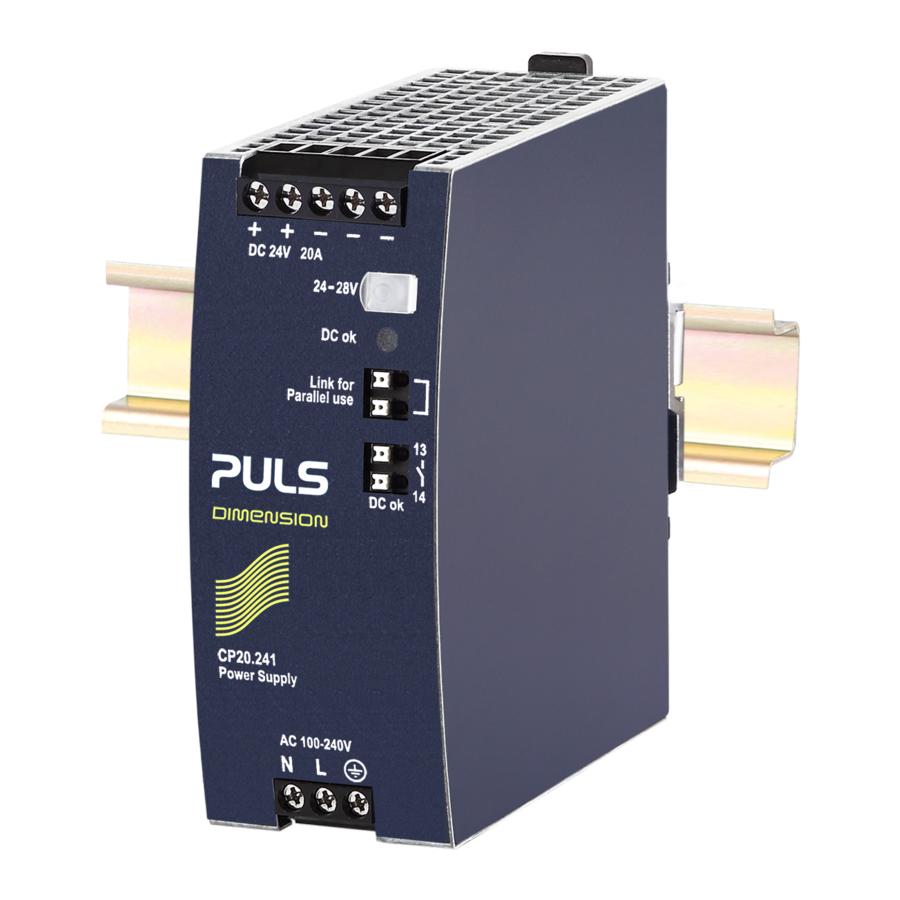
The CP20.248 is a DIN-rail mountable single-phase-input power
supply, which provides a floating, stabilized and galvanically
separated SELV/PELV output voltage.
The device has a condition display integrated which shows real-
time and recorded data informing about the condition of the
power supply and the power line.
A DC OK signal, an alarm signal and remote ON/OFF make the
unit suitable for many applications, where preventive function
monitoring and remote control can help to avoid costly
downtimes.
The device has a power reserve of 20% included, which may
even be used continuously up to +45°C. Additionally it can
deliver 3 times the nominal output current for 12ms, which
helps to trip fuses on faulty output branches.
The device is equipped with a "Single Use / Parallel Use" feature,
which enables a load sharing between power supplies when
they are connected in parallel.
The Dimension CP-Series are cost optimized power supplies
without compromising quality, reliability and performance. The
most outstanding features of this series are the high efficiency,
electronic inrush current limitation, active PFC, wide operational
temperature range and the extraordinary small size.
O
N
RDER
UMBERS
Power Supply
CP20.248
Mechanical Accessory
ZM10.WALL Wall/Panel mount bracket
May 2020 / Rev 0.1 DS-CP20.248-EN All parameters are typical values specified 230Vac, 50Hz input voltage, 24V, 20A output load,
25°C ambient and after a 5 minutes run-in time unless otherwise noted.
P
OWER
▪ AC 100-240V Wide-range input
▪ Width only 48mm
▪ Display for condition monitoring and easy analysis of
power errors
▪ Efficiency up to 95.6%
▪ 20% output power reserves
▪ Easy Fuse Breaking – 3 times nominal current for 12ms
▪ Safe Hiccup
▪ Full power between -25°C and +60°C
▪ DC OK relay contact
▪ ALARM relay contact
▪ Remote ON/OFF functionality
▪ Current sharing feature for parallel use
▪ 3 Year Warranty
S
Output voltage
Adjustment range
Output current
Input voltage AC
Mains frequency
Input current AC
Power factor
Input voltage DC
Input current DC
AC Inrush current
Efficiency
Losses
Hold-up time
Temperature range
Size (WxHxD)
Weight
M
For details or a complete approval list see section 22.
www.pulspower.com Phone +49 89 9278 0 Germany
24V, 20A, 480W, S
S
UPPLY
PLUS
Overload Mode
-
D
HORT
FORM
ATA
DC 24V
24 - 28V
24.0 - 20.6A
20.0 – 17.1A
15.0 – 13.0A
Derate between +45°C and +70°C
AC 100-240V
50-60Hz
4.26 / 2.23A
0.99 / 0.98
DC 110-150V
4.64A
10.0 / 4.5Apk
94.2 / 95.6%
29.6 / 22.1W
32/ 32ms
-25°C to +70°C
48x124x127mm
835g / 1.84lb
A
AIN
PPROVALS
IEC 61010-2-201
(planned)
CP20.248
P
INGLE
HASE
Nominal
Factory setting 24.1V
Below +45°C ambient
At +60°C ambient
At +70°C ambient
-15%/+10%
±6%
At 120 / 230Vac
At 120 / 230Vac
±20%
At 110Vdc
At 120 / 230Vac
At 120 / 230Vac
At 120 / 230Vac
At 120 / 230Vac
Without DIN-rail
1/33
Advertisement
Table of Contents

Related Manuals for Puls DIMENSION CP Series


Summary of Contents for Puls DIMENSION CP Series
- Page 1 CP20.248 24V, 20A, 480W, S CP-Series INGLE HASE OWER UPPLY ▪ AC 100-240V Wide-range input ▪ Width only 48mm ▪ Display for condition monitoring and easy analysis of power errors ▪ Efficiency up to 95.6% ▪ 20% output power reserves ▪...
-
Page 2: Table Of Contents
CP20.248 24V, 20A, 480W, S CP-Series INGLE HASE NDEX Page Page Intended Use ..............3 22. Approvals ..............23 Installation Instructions ..........4 23. Regulatory Compliance ..........23 AC-Input ............... 5 24. Physical Dimensions and Weight ....... 24 DC-Input ............... 6 25. -
Page 3: Intended Use
CP20.248 24V, 20A, 480W, S CP-Series INGLE HASE 1. I NTENDED This device is designed for installation in an enclosure and is intended for commercial use, such as in industrial control, process control, monitoring and measurement equipment or the like. Do not use this device in equipment, where malfunctioning may cause severe personal injury or threaten human life without additional appropriate safety devices, that are suited for the end-application. -
Page 4: Installation Instructions
CP20.248 24V, 20A, 480W, S CP-Series INGLE HASE 2. I NSTALLATION NSTRUCTIONS WARNING Risk of electrical shock, fire, personal injury or death - Turn power off before working on the device. Protect against inadvertent re-powering. - Do not modify or repair the unit. - Do not open the unit as high voltages are present inside. -
Page 5: Ac-Input
CP20.248 24V, 20A, 480W, S CP-Series INGLE HASE 3. AC-I NPUT The device is suitable to be supplied from TN, TT or IT mains networks. AC input nom. AC 100-240V AC input range 85-264Vac Continuous operation 264-300Vac Occasionally for maximal 500ms Allowed voltage L or N to earth max. -
Page 6: Dc-Input
CP20.248 24V, 20A, 480W, S CP-Series INGLE HASE 4. DC-I NPUT The device is suitable to be supplied from a DC input voltage. Use a battery or a similar DC source. A supply from the intermediate DC-bus of a frequency converter is not recommended and can cause a malfunction or damage the unit. Connect +pole to L, –pole to N and the PE terminal to an earth wire or to the machine ground. -
Page 7: Output
CP20.248 24V, 20A, 480W, S CP-Series INGLE HASE 6. O UTPUT The output provides a SELV/PELV rated voltage, which is galvanically isolated from the input voltage. The output is electronically protected against no-load, overload and short circuit. In case of a protection event, audible noise may occur. The output is designed to supply any kind of loads, including inductive and capacitive loads. - Page 8 CP20.248 24V, 20A, 480W, S CP-Series INGLE HASE Back-feeding loads Max. The unit is resistant and does not show malfunctioning when a load feeds back voltage to the power supply. It does not matter whether the power supply is on or off. The absorbing energy can be calculated according to the built-in large sized output capacitor.
-
Page 9: Hold-Up Time
CP20.248 24V, 20A, 480W, S CP-Series INGLE HASE 7. H The hold-up time is the time during which a power supply’s output voltage remains within specification following the loss of input power. The hold-up time is output load dependent. At no load, the hold-up time can be up to several seconds. The green DC OK lamp is also on during this time. -
Page 10: Power Supply Condition Display
CP20.248 24V, 20A, 480W, S CP-Series INGLE HASE 9. P OWER UPPLY ONDITION ISPLAY The device has an integrated Power Supply Condition Display (PSCD), which shows power supply condition values on front of the unit. When the power supply is powered on, all LED segments of the PSCD are switched on for 2 seconds to indicate that all segments of the display are fully-functional. - Page 11 CP20.248 24V, 20A, 480W, S CP-Series INGLE HASE Error Codes In the event of an external error, the “Alarm contact” is closed and the status indicator shows “Alarm”. Error details are displayed in the denomination field and in the running text, which provides an error code. - “Err2”...
-
Page 12: Remote On / Off Function
CP20.248 24V, 20A, 480W, S CP-Series INGLE HASE 10. R ON / OFF F EMOTE UNCTION This feature enables the output to switch off by signal input. A link between pin 15 and 16 turns the power supply off. Pin 15 is referenced to the (-) output voltage. R emote ON/OF F When multiple power supplies are connected in parallel, pin 15 and pin 16 are also allowed to be... -
Page 13: Efficiency And Power Losses
CP20.248 24V, 20A, 480W, S CP-Series INGLE HASE 12. E FFICIENCY AND OWER OSSES AC 100V AC 120V AC 230V Efficiency typ. 93.6% 94.2% 95.6% At 24V, 20A typ. 93.5% 94.1% 95.5% At 24V, 24A (Power Boost) Average efficiency typ. 93.2% 93.8% 95.0%... -
Page 14: Functional Diagram
CP20.248 24V, 20A, 480W, S CP-Series INGLE HASE 13. F UNCTIONAL IAGRAM Fig. 13-1 Functional diagram In p u t F u s e In p u t F ilt e r P o w e r O u t p u t P F C In p u t R e c t if ie r C o n v e r t e r... -
Page 15: Front Side And User Elements
CP20.248 24V, 20A, 480W, S CP-Series INGLE HASE 14. F RONT IDE AND LEMENTS Fig. 14-1 Front side Output Terminals Three terminals for the negative and two terminals for the positive pole. Poles are internally connected. + Positive output - Negative (return) output Input Terminals Phase (Line) input Neutral conductor input... -
Page 16: Connection Terminals
CP20.248 24V, 20A, 480W, S CP-Series INGLE HASE 15. C ONNECTION ERMINALS The terminals are IP20 Finger safe constructed and suitable for field- and factory wiring. Input Output Signal Terminals Type Screw termination Screw termination Push-in termination Solid wire max. 6mm Max. -
Page 17: Lifetime Expectancy
CP20.248 24V, 20A, 480W, S CP-Series INGLE HASE 16. L IFETIME XPECTANCY The Lifetime expectancy shown in the table indicates the minimum operating hours (service life) and is determined by the lifetime expectancy of the built-in electrolytic capacitors. Lifetime expectancy is specified in operational hours and is calculated according to the capacitor’s manufacturer specification. -
Page 18: 18. Emc
CP20.248 24V, 20A, 480W, S CP-Series INGLE HASE 18. EMC The EMC behavior of the device is designed for applications in industrial environment as well as in residential, commercial and light industry environments. The device complies with EN 61000-6-1, EN 61000-6-2, EN 61000-6-3, EN 61000-6-4, EN 61000-3-2 and EN 61000-3-3. The device complies with FCC Part 15 rules. - Page 19 CP20.248 24V, 20A, 480W, S CP-Series INGLE HASE EMC Emission Conducted emission EN 55011, EN 55032, FCC Part 15, CISPR 11, CISPR Class B input lines Conducted emission IEC/CISPR 16-1-2, IEC/CISPR 16-2-1 Limits for local DC power networks not output lines fulfilled.
-
Page 20: Environment
CP20.248 24V, 20A, 480W, S CP-Series INGLE HASE 19. E NVIRONMENT Operational temperature -25°C to +70°C (-13°F to 158°F) The operational temperature is the ambient or surrounding temperature and is defined as the air temperature 2cm below the device. Storage temperature -40°C to +85°C (-40°F to 185°F) For storage and transportation Output de-rating... -
Page 21: Safety And Protection Features
CP20.248 24V, 20A, 480W, S CP-Series INGLE HASE 20. S AFETY AND ROTECTION EATURES Isolation resistance min. 500MOhm At delivered condition between input and output, measured with 500Vdc min. 500MOhm At delivered condition between input and PE, measured with 500Vdc min. -
Page 22: Dielectric Strength
CP20.248 24V, 20A, 480W, S CP-Series INGLE HASE 21. D IELECTRIC TRENGTH The output voltage is floating and has no ohmic connection to the ground. The output is insulated to the input by a double or reinforced insulation. Type and routine tests are conducted by the manufacturer. Field tests may be conducted in the field using the appropriate test equipment which applies the voltage with a slow ramp (2s up and 2s down). -
Page 23: Approvals
CP20.248 24V, 20A, 480W, S CP-Series INGLE HASE 22. A PPROVALS IEC 61010 CB Scheme Certificate IEC 61010-2-201 Electrical Equipment for Measurement, Control and planned Laboratory Use - Particular requirements for control equipment IEC 62368-1 CB Scheme Certificate IEC 62368-1 Audio/video, information and communication technology planned equipment - Safety requirements Output safety level: ES1... -
Page 24: Physical Dimensions And Weight
CP20.248 24V, 20A, 480W, S CP-Series INGLE HASE 24. P HYSICAL IMENSIONS AND EIGHT Width 48mm 1.89’’ Height 124mm 4.88’’ Depth 127mm 5.0’’ The DIN-rail height must be added to the unit depth to calculate the total required installation depth. Weight 840g / 1.84lb DIN-Rail... -
Page 25: Accessories
CP20.248 24V, 20A, 480W, S CP-Series INGLE HASE 25. A CCESSORIES 25.1. ZM10.WALL – W ANEL OUNT RACKET This bracket is used to mount the devices on a wall/panel without utilizing the DIN-Rail. The bracket can be mounted without detaching the DIN-rail brackets from the power supply. -
Page 26: Uf20.241 Buffer Module
CP20.248 24V, 20A, 480W, S CP-Series INGLE HASE 25.2. UF20.241 B UFFER ODULE The UF20.241 buffer module is a supplementary device for DC 24V power supplies. It delivers power to bridge typical mains failures or extends the hold-up time after the AC power is turned off. When the power supply provides a sufficient voltage, the buffer module stores energy in the integrated electrolytic capacitors. -
Page 27: Yr40.245 - Redundancy Modules
CP20.248 24V, 20A, 480W, S CP-Series INGLE HASE 25.5. YR40.245 - R EDUNDANCY ODULES The YR40.245 is a 40A single channel redundancy module, which is equipped with a plug connector on the output. The plug connector allows replacing the power supply or the redundancy module while the system is running. The plug connector prevents the output wires from touching and creating a short the load circuit. -
Page 28: Application Notes
CP20.248 24V, 20A, 480W, S CP-Series INGLE HASE 26. A PPLICATION OTES 26.1. P URRENT APABILITY The unit can deliver peak currents (up to several milliseconds) which are higher than the specified short term currents. This helps to start current demanding loads. Solenoids, contactors and pneumatic modules often have a steady state coil and a pick-up coil. -
Page 29: Output Circuit Breakers
CP20.248 24V, 20A, 480W, S CP-Series INGLE HASE 26.2. O UTPUT IRCUIT REAKERS Standard miniature circuit breakers (MCB’s or UL 1077 circuit breakers) are commonly used for AC-supply systems and may also be used on 24V branches. MCB’s are designed to protect wires and circuits. If the ampere value and the characteristics of the MCB are adapted to the wire size that is used, the wiring is considered as thermally safe regardless of whether the MCB opens or not. -
Page 30: Charging Of Batteries
CP20.248 24V, 20A, 480W, S CP-Series INGLE HASE 26.3. C HARGING OF ATTERIES The power supply can be used to charge lead-acid or maintenance-free batteries. Two 12V SLA or VRLA batteries are needed in series connection. Instructions for charging batteries: Use only matched batteries when putting 12V types in series. -
Page 31: Parallel Use For Redundancy
CP20.248 24V, 20A, 480W, S CP-Series INGLE HASE 26.6. P ARALLEL SE FOR EDUNDANCY 1+1 Redundancy: Devices can be paralleled for redundancy to gain higher system availability. Redundant systems require a certain amount of extra power to support the load in case one device fails. The simplest way is to put two devices in parallel. This is called a 1+1 redundancy. In case one device fails, the other one is automatically able to support the load current without any interruption. -
Page 32: Operation On Two Phases
CP20.248 24V, 20A, 480W, S CP-Series INGLE HASE 26.7. O PERATION ON HASES The power supply can also be used on two-phases of a three-phase-system. Such a P ower S upply phase-to-phase connection is allowed as long as the supplying voltage is below 240V +10% Ensure that the wire, which is connected to the N-terminal, is appropriately fused. -
Page 33: Mounting Orientations
CP20.248 24V, 20A, 480W, S CP-Series INGLE HASE 26.9. M OUNTING RIENTATIONS Mounting orientations other than the standard mounting orientation require a reduction in continuous output power or a limitation in the maximum allowed ambient temperature. The listed lifetime and MTBF values from this datasheet apply only for the standard mounting orientation. The following curves give an indication for allowed output currents for altitudes up to 2000m (6560ft).
Need help?
Do you have a question about the DIMENSION CP Series and is the answer not in the manual?
Questions and answers
how to do temperature calibration of CP20.348 SMPS, because it shows wrong temperature.