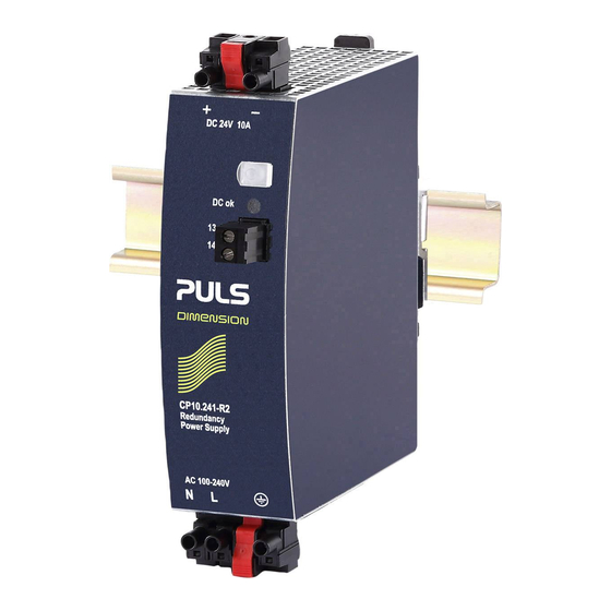
Puls Dimension CP Series Manual

Puls Dimension CP Series Manual

24v, 10a, 240w, single phase
Hide thumbs Also See for Dimension CP Series:

Advertisement

Quick Links

CP-Series
G
D
ENERAL
ESCRIPTION
The Dimension CP-Series are cost optimized power
supplies without compromising quality, reliability and
performance. The most outstanding features of the
CP10.241–R1/-R2/-R3 units are the high efficiency,
electronic inrush current limitation, active PFC, wide
operational temperature range and the extraordinary
small size. The units include a decoupling MOSFET for
building 1+1 or n+1 redundant power supply systems.
These redundancy power supplies come with three
connection terminal options; screw terminals, spring-
clamp terminals or plug connector terminals which
allows replacement on an active application.
CP10.242-R2 version feature an enhanced DC input
voltage range.
With high immunity to transients and power surges, low
electromagnetic emission, a DC-OK signal contact for
remote monitoring, and a large international approval
package, makes this unit suitable for nearly every
application.
O
N
RDER
UMBERS
Power Supplies
CP10.241-R1
With quick-connect spring-clamp
terminals
CP10.241-R2
With hot swappable plug
connectors (preferred item)
CP10.241-R3
With screw terminals
CP10.242-R2
Enhanced DC-Input
Mechanical Accessory
ZM4.WALL
Wall/panel mount bracket
ZM12.SIDE
Side mount bracket
Feb. 2018 / CP10.241-R2 Rev0.3-EN - All values are typical figures specified at 230Vac, 50Hz input voltage, 24V, 10A output
load, 25°C ambient and after a 5 minutes run-in time unless otherwise noted.
P R E L I M I N A R Y
R
www.pulspower.com Phone +49 89 9278 0
CP10.241-R1, CP10.241-R2,
CP10.241-R3,CP10.242-R2
24V, 10A, 240W, S
P
EDUNDANCY
OWER
AC 100-240V Wide-range Input
Width only 39mm
Built-in Decoupling Mosfet for 1+1 and n+1 Redundancy
Efficiency up to 94.7%
20% Output Power Reserves
PLUS
Safe Hiccup
Overload Mode
Easy Fuse Breaking – 3 times nominal current for 12ms
Active Power Factor Correction (PFC)
Minimal Inrush Current Surge
Full Power Between -25°C and +60°C
DC-OK Relay Contact
Current Sharing Feature Included
3 Year Warranty
S
-
D
HORT
FORM
ATA
Output voltage
DC 24V
Adjustment range
-
Output current
12A
10A
7.5A
Derate linearely between +45°C and +70°C
AC Input voltage
AC 100-240V
Mains frequency
50-60Hz
AC Input current
2.17 / 1.14A
Power factor
0.99 / 0.97
Input voltage DC
DC 110-150V
DC 110-300V
Input current DC
2.35A / 0.84A
AC Inrush current
6 / 9Apk
Efficiency
93.0 / 94.7%
Losses
18.1 / 13.4W
Hold-up time
37 / 37ms
Temperature range
-25°C to +70°C
Size (w x h x d)
39x124x117mm
Weight
600g / 1.32lb
M
ARKINGS
For details or a complete approval list see section 20.
Germany
P
INGLE
HASE
S
UPPLY
0%/+6%
Below +45°C ambient
At +60°C ambient
At +70°C ambient
-15%/+10%
±6%
At 120 / 230Vac
At 120 / 230Vac
±20%
For CP10.241-Rx
±20%
For CP10.242-R2
At 110 / 300Vdc
At 120 / 230Vac
At 120 / 230Vac
At 120 / 230Vac
At 120 / 230Vac
Without DIN-rail and
plug connectors
1/31

Advertisement

Table of Contents
loading
Need help?

Need help?

Do you have a question about the Dimension CP Series and is the answer not in the manual?

Questions and answers

Subscribe to Our Youtube Channel

Summary of Contents for Puls Dimension CP Series

  • Page 1 P R E L I M I N A R Y CP10.241-R1, CP10.241-R2, CP10.241-R3,CP10.242-R2 24V, 10A, 240W, S CP-Series INGLE HASE EDUNDANCY OWER UPPLY AC 100-240V Wide-range Input Width only 39mm Built-in Decoupling Mosfet for 1+1 and n+1 Redundancy Efficiency up to 94.7% 20% Output Power Reserves PLUS Safe Hiccup...
  • Page 2: Table Of Contents

    P R E L I M I N A R Y CP10.241-R1, CP10.241-R2, CP10.241-R3,CP10.242-R2 24V, 10A, 240W, S CP-Series INGLE HASE NDEX Page Page Intended Use ............4 20. Approvals ............21 Installation Requirements........4 21. Other Fulfilled Standards ......... 21 AC-Input...............5 22.
  • Page 3 P R E L I M I N A R Y CP10.241-R1, CP10.241-R2, CP10.241-R3,CP10.242-R2 24V, 10A, 240W, S CP-Series INGLE HASE ERMINOLOGY AND BREVIATIONS PE and symbol PE is the abbreviation for Protective Earth and has the same meaning as the symbol Earth, Ground This document uses the term “earth”...
  • Page 4: Intended Use

    P R E L I M I N A R Y CP10.241-R1, CP10.241-R2, CP10.241-R3,CP10.242-R2 24V, 10A, 240W, S CP-Series INGLE HASE 1. I NTENDED This device is designed for installation in an enclosure and is intended for the general professional use such as in industrial control, office, communication, and instrumentation equipment.
  • Page 5: Ac-Input

    P R E L I M I N A R Y CP10.241-R1, CP10.241-R2, CP10.241-R3,CP10.242-R2 24V, 10A, 240W, S CP-Series INGLE HASE 3. AC-I NPUT The device is suitable to be supplied from TN-, TT- and IT mains networks with AC voltage. For suitable DC supply voltages see chapter 4.
  • Page 6: Dc-Input

    P R E L I M I N A R Y CP10.241-R1, CP10.241-R2, CP10.241-R3,CP10.242-R2 24V, 10A, 240W, S CP-Series INGLE HASE 4. DC-I NPUT The device is suitable to be supplied from a DC input voltage. Use a battery or a similar DC source. A supply from the intermediate DC-bus of a frequency converter is not recommended and can cause a malfunction or damage the unit.
  • Page 7: Input Inrush Current

    P R E L I M I N A R Y CP10.241-R1, CP10.241-R2, CP10.241-R3,CP10.242-R2 24V, 10A, 240W, S CP-Series INGLE HASE 5. I NPUT NRUSH URRENT An active inrush limitation circuit (NTCs, which are bypassed by a relay contact) limits the input inrush current after turn-on of the input voltage.
  • Page 8: Output

    P R E L I M I N A R Y CP10.241-R1, CP10.241-R2, CP10.241-R3,CP10.242-R2 24V, 10A, 240W, S CP-Series INGLE HASE 6. O UTPUT The output provides a SELV/PELV/ES1 rated voltage, which is galvanically isolated from the input voltage. The output of the devices includes a decoupling MOSFET for building 1+1 or n+1 redundant power supply systems.
  • Page 9: Hold-Up Time

    P R E L I M I N A R Y CP10.241-R1, CP10.241-R2, CP10.241-R3,CP10.242-R2 24V, 10A, 240W, S CP-Series INGLE HASE PLUS Fig. 6-1 Output voltage vs. output current, typ. Fig. 6-2 Short-circuit on output, Hiccup mode, typ. Output Voltage Output Current Normal...
  • Page 10: Dc-Ok Relay Contact

    P R E L I M I N A R Y CP10.241-R1, CP10.241-R2, CP10.241-R3,CP10.242-R2 24V, 10A, 240W, S CP-Series INGLE HASE 8. DC-OK R ELAY ONTACT This feature monitors the output voltage of the power supply in front of the decoupling device (see also chapter 12). Contact closes As soon as the output voltage reaches typically 22Vdc.
  • Page 11: Efficiency And Power Losses

    P R E L I M I N A R Y CP10.241-R1, CP10.241-R2, CP10.241-R3,CP10.242-R2 24V, 10A, 240W, S CP-Series INGLE HASE 9. E FFICIENCY AND OWER OSSES AC 100V AC 120V AC 230V Efficiency Typ. 92.2% 93.0% 94.7% At 10A Typ.
  • Page 12: Lifetime Expectancy

    P R E L I M I N A R Y CP10.241-R1, CP10.241-R2, CP10.241-R3,CP10.242-R2 24V, 10A, 240W, S CP-Series INGLE HASE 10. L IFETIME XPECTANCY The Lifetime expectancy shown in the table indicates the minimum operating hours (service life) and is determined by the lifetime expectancy of the built-in electrolytic capacitors.
  • Page 13: Functional Diagram

    P R E L I M I N A R Y CP10.241-R1, CP10.241-R2, CP10.241-R3,CP10.242-R2 24V, 10A, 240W, S CP-Series INGLE HASE 12. F UNCTIONAL IAGRAM Fig. 12-1 Functional diagram CP10.241-R1 and CP10.241-R3 Input Fuse Input Filter Output Power Decoupling Filter Converter Input Rectifier Converter...
  • Page 14: Terminals And Wiring

    P R E L I M I N A R Y CP10.241-R1, CP10.241-R2, CP10.241-R3,CP10.242-R2 24V, 10A, 240W, S CP-Series INGLE HASE 13. T ERMINALS AND IRING The terminals are IP20 Finger safe constructed and suitable for field- and factory wiring. CP10.241-R1 Input Output...
  • Page 15 P R E L I M I N A R Y CP10.241-R1, CP10.241-R2, CP10.241-R3,CP10.242-R2 24V, 10A, 240W, S CP-Series INGLE HASE 14. R EPLACING NITS WHILE THE YSTEM IS UNNING This feature is available only for the CP10.241-R2 and CP10.242-R2 units, which are equipped with hot-swappable plug connectors.
  • Page 16: Front Side And User Elements

    P R E L I M I N A R Y CP10.241-R1, CP10.241-R2, CP10.241-R3,CP10.242-R2 24V, 10A, 240W, S CP-Series INGLE HASE 15. F RONT IDE AND LEMENTS Fig. 15-2 Front side Fig. 15-1 Front side Fig. 15-3 Front side CP10.241-R2 CP10.241-R1 CP10.241-R3 CP10.242-R2...
  • Page 17: 16. Emc

    P R E L I M I N A R Y CP10.241-R1, CP10.241-R2, CP10.241-R3,CP10.242-R2 24V, 10A, 240W, S CP-Series INGLE HASE 16. EMC The EMC behavior of the device is designed for applications in industrial environment as well as in residential, commercial and light industry environments.
  • Page 18: Environment

    P R E L I M I N A R Y CP10.241-R1, CP10.241-R2, CP10.241-R3,CP10.242-R2 24V, 10A, 240W, S CP-Series INGLE HASE 17. E NVIRONMENT Operational temperature -25°C to +70°C (-13°F to 158°F) Operational temperature is the same as the ambient or surrounding temperature and is defined as the air temperature 2cm below the unit.
  • Page 19: Safety And Protection Features

    P R E L I M I N A R Y CP10.241-R1, CP10.241-R2, CP10.241-R3,CP10.242-R2 24V, 10A, 240W, S CP-Series INGLE HASE 18. S AFETY AND ROTECTION EATURES Isolation resistance Min. 500MOhm At delivered condition between input and output, measured with 500Vdc Min.
  • Page 20: Dielectric Strength

    P R E L I M I N A R Y CP10.241-R1, CP10.241-R2, CP10.241-R3,CP10.242-R2 24V, 10A, 240W, S CP-Series INGLE HASE 19. D IELECTRIC TRENGTH The output voltage is floating and has no ohmic connection to the ground. Type and routine tests are conducted by the manufacturer.
  • Page 21: Approvals

    P R E L I M I N A R Y CP10.241-R1, CP10.241-R2, CP10.241-R3,CP10.242-R2 24V, 10A, 240W, S CP-Series INGLE HASE 20. A PPROVALS EC Declaration of Conformity The CE mark indicates conformance with the - EMC directive, - Low-voltage directive and the - ATEX directive (planned) IEC 60950-1 CB Scheme for I.T.E.
  • Page 22: Physical Dimensions And Weight

    P R E L I M I N A R Y CP10.241-R1, CP10.241-R2, CP10.241-R3,CP10.242-R2 24V, 10A, 240W, S CP-Series INGLE HASE 22. P HYSICAL IMENSIONS AND EIGHT Width 39mm 1.54’’ Height 124mm 4.88’’ (without plug-connectors) Depth 117mm 4.61’’ (without plug-connector) The DIN-rail height must be added to the unit depth to calculate the total required installation depth.
  • Page 23: Accessories

    P R E L I M I N A R Y CP10.241-R1, CP10.241-R2, CP10.241-R3,CP10.242-R2 24V, 10A, 240W, S CP-Series INGLE HASE 23. A CCESSORIES 23.1. ZM4.WALL – W ANEL OUNT RACKET This bracket is used to mount the devices on a wall/panel without utilizing a DIN-Rail and can be mounted without detaching the DIN-rail brackets of the power supply.
  • Page 24: Zm4.Wall - Wall/Panel Mount Bracket .23 23.2. Zm12.Side - Side Mounting Bracket

    P R E L I M I N A R Y CP10.241-R1, CP10.241-R2, CP10.241-R3,CP10.242-R2 24V, 10A, 240W, S CP-Series INGLE HASE 23.2. ZM12.SIDE - S OUNTING RACKET This bracket is used to mount the power supply sideways with or without utilizing a DIN-Rail. The two aluminum brackets and the black plastic slider of the unit have to be detached, so that the steel brackets can be mounted.
  • Page 25: Application Notes

    P R E L I M I N A R Y CP10.241-R1, CP10.241-R2, CP10.241-R3,CP10.242-R2 24V, 10A, 240W, S CP-Series INGLE HASE 24. A PPLICATION OTES 24.1. P URRENT APABILITY The unit can deliver peak currents (up to several milliseconds) which are higher than the specified short term currents. This helps to start current demanding loads.
  • Page 26: Adjusting The Output Voltage

    P R E L I M I N A R Y CP10.241-R1, CP10.241-R2, CP10.241-R3,CP10.242-R2 24V, 10A, 240W, S CP-Series INGLE HASE 24.2. A DJUSTING THE UTPUT OLTAGE A voltage adjustment potentiometer can be found behind the flap on the front of the unit. However, it is not recommended to change the output voltage since load sharing between power supplies connected in parallel can only be achieved by a precise setting of the output voltages.
  • Page 27: Charging Of Batteries

    P R E L I M I N A R Y CP10.241-R1, CP10.241-R2, CP10.241-R3,CP10.242-R2 24V, 10A, 240W, S CP-Series INGLE HASE 24.3. C HARGING OF ATTERIES This redundancy power supply is ideal for charging batteries due to the decoupling circuit built in to the output stage which does not require a fuse or diode between the power supply and the battery.
  • Page 28: Series Operation

    P R E L I M I N A R Y CP10.241-R1, CP10.241-R2, CP10.241-R3,CP10.242-R2 24V, 10A, 240W, S CP-Series INGLE HASE 24.5. S ERIES PERATION Power supplies of the same type can be connected in series for higher Unit A Input output voltages.
  • Page 29: Parallel Use For Redundancy

    P R E L I M I N A R Y CP10.241-R1, CP10.241-R2, CP10.241-R3,CP10.242-R2 24V, 10A, 240W, S CP-Series INGLE HASE 24.7. P ARALLEL SE FOR EDUNDANCY Power supplies can be paralleled for redundancy to gain higher system availability. The unit is already equipped with a MOSFET as decoupling device on the output to avoid, that a faulty unit becomes a load for the other power supplies and the output voltage cannot be maintained any more.
  • Page 30: Operation On Two Phases

    P R E L I M I N A R Y CP10.241-R1, CP10.241-R2, CP10.241-R3,CP10.242-R2 24V, 10A, 240W, S CP-Series INGLE HASE 24.8. O PERATION ON HASES Power Supply The power supply can also be used on two-phases of a three-phase- system.
  • Page 31: Mounting Orientations

    P R E L I M I N A R Y CP10.241-R1, CP10.241-R2, CP10.241-R3,CP10.242-R2 24V, 10A, 240W, S CP-Series INGLE HASE 24.10. M OUNTING RIENTATIONS Mounting orientations other than all terminals on the bottom require a reduction in continuous output power or a limitation in the maximum allowed ambient temperature.

This manual is also suitable for:

Cp10.241-r2Cp10.241-r1Cp10.241-r3Cp10.242-r2

Table of Contents