Puls Dimension CP Series Manual
Hide thumbs
Also See for Dimension CP Series:
- Manual (278 pages) ,
- Quick start manual (29 pages) ,
- User manual (28 pages)
Table of Contents
Advertisement
Quick Links
Download this manual
See also:
Manual
CP-Series
P
D
RODUCT
ESCRIPTION
The Dimension CP-Series are cost optimized power
supplies without compromising quality, reliability and
performance. The CP-Series is part of the DIMENSION
power supply family.
The CP5.241 power supplies come with three connection
terminal
options:
screw,
terminals, which are optimized for automated wiring.
The CP5.241-C1 is equipped with conformal coated pc-
boards preferred for the use in harsh environments and
the CP5.242 features an enhanced DC input voltage
range.
The most outstanding features of these units are the
small size, the high efficiency, the electronic inrush
current limitation, active PFC and the wide operational
temperature range. The devices have a power reserve of
20% included, which may even be used continuously at
temperatures up to +45°C. Additionally, they can deliver
3 times the nominal output current for 12ms which
helps to trip fuses on faulty output branches.
High immunity to transients and power surges as well as
low electromagnetic emission, a DC-OK signal contact
for remote monitoring, and a large international
approval package for a variety of applications makes
this unit suitable for nearly every situation.
O
N
RDER
UMBERS
Power Supply CP5.241
CP5.241-C1 Screw terminals and
CP5.241-S1 Spring-clamp terminals
CP5.241-S2 Push-in terminals
CP5.242
Mechanical Accessory
ZM10.WALL Wall/Panel mount bracket
Jul. 2019 / Rev. 1.0 DS-CP5.241-EN
25°C ambient and after a 5 minutes run-in time unless otherwise noted.
spring-clamp
or
push-in
Screw terminals
conformal coated pc-boards
Screw terminals and
enhanced DC input
All parameters are typical values specified at 230Vac, 50Hz input voltage, 24V, 5A output load,
www.pulspower.com Phone +49 89 9278 0
CP5.241, CP5.241-C1, CP5.241-S1,
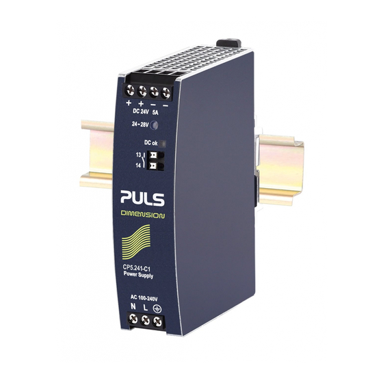
24V, 5A, 120W, S
P
S
OWER
UPPLY
AC 100-240V Wide-range Input
Width only 32mm
Efficiency up to 94.3%
Excellent Partial Load Efficiency
20% Output Power Reserves
Easy Fuse Breaking – 3 times nominal current for 12ms
PLUS
Safe Hiccup
Active Power Factor Correction (PFC)
Minimal Inrush Current Surge
Full Power Between -25°C and +60°C
DC-OK Relay Contact
3 Year Warranty
S
-
HORT
FORM
Output voltage
Adjustment range
Output current
Input voltage AC
Mains frequency
Input current AC
Power factor
Input voltage DC
Input current DC
AC Inrush current
Efficiency
Losses
Hold-up time
Temperature range
Size (WxHxD)
Weight
M
A
AIN
PPROVALS
For details or a complete approval list see chapter 19.
IEC 62368-1
IEC 61010-1
IEC 61010-2-201
CP5.241-S2, CP5.242
INGLE
Overload Mode
D
ATA
DC 24V
Nominal
24 - 28V
Factory setting 24.1V
6.0 - 5.1A
Below +45°C ambient
5.0 – 4.3A
At +60°C ambient
3.8 – 3.2A
At +70°C ambient
Derate linearly between +45°C and +70°C
AC 100-240V
-15%/+10%
50-60Hz
±6%
1.09 / 0.6A
At 120 / 230Vac
0.98 / 0.91
At 120 / 230Vac
±20%
DC 110-150V
For CP5.241 (-xx)
±20%
DC 110-300V
For CP5.242
1.21 / 0.43A
At 110 / 300Vdc
4 / 4A
At 120 / 230Vac
93.6 / 94.3%
At 120 / 230Vac
8.2 / 7.3W
At 120 / 230Vac
35 / 35ms
At 120 / 230Vac
-25°C to +70°C
32x124x102mm
Without DIN-rail
440g / 0.97lb
IND. CONT. EQ.
planned
Germany
P
I
HASE
NPUT
1/29
Advertisement
Table of Contents

Related Manuals for Puls Dimension CP Series


Summary of Contents for Puls Dimension CP Series
- Page 1 CP5.241, CP5.241-C1, CP5.241-S1, CP5.241-S2, CP5.242 24V, 5A, 120W, S CP-Series INGLE HASE NPUT OWER UPPLY AC 100-240V Wide-range Input Width only 32mm Efficiency up to 94.3% Excellent Partial Load Efficiency 20% Output Power Reserves Easy Fuse Breaking – 3 times nominal current for 12ms PLUS Safe Hiccup Overload Mode...
-
Page 2: Table Of Contents
CP5.241, CP5.241-C1, CP5.241-S1, CP5.241-S2, CP5.242 24V, 5A, 120W, S CP-Series INGLE HASE NPUT NDEX Page Page Intended Use ............3 20. Regulatory Compliance ........19 Installation Instructions ........3 21. Physical Dimensions and Weight ..... 20 AC-Input...............5 22. Accessories ............21 DC-Input...............6 22.1. -
Page 3: Intended Use
CP5.241, CP5.241-C1, CP5.241-S1, CP5.241-S2, CP5.242 24V, 5A, 120W, S CP-Series INGLE HASE NPUT 1. I NTENDED This device is designed for installation in an enclosure and is intended for commercial use, such as in industrial control, process control, monitoring and measurement equipment or the like. Do not use this device in equipment where malfunction may cause severe personal injury or threaten human life. - Page 4 CP5.241, CP5.241-C1, CP5.241-S1, CP5.241-S2, CP5.242 24V, 5A, 120W, S CP-Series INGLE HASE NPUT Keep the following minimum installation clearances: 40mm on top, 20mm on the bottom, 5mm left and right side. Increase the 5mm to 15mm in case the adjacent device is a heat source. When the device is permanently loaded with less than 50%, the 5mm can be reduced to zero.
-
Page 5: Ac-Input
CP5.241, CP5.241-C1, CP5.241-S1, CP5.241-S2, CP5.242 24V, 5A, 120W, S CP-Series INGLE HASE NPUT 3. AC-I NPUT The device is suitable to be supplied from TN, TT or IT mains networks with AC voltage. For suitable DC supply voltages see chapter 4. AC input Nom. -
Page 6: Dc-Input
CP5.241, CP5.241-C1, CP5.241-S1, CP5.241-S2, CP5.242 24V, 5A, 120W, S CP-Series INGLE HASE NPUT 4. DC-I NPUT The device is suitable to be supplied from a DC input voltage. Use a battery or a similar DC source. A supply from the intermediate DC-bus of a frequency converter is not recommended and can cause a malfunction or damage the unit. -
Page 7: Input Inrush Current
CP5.241, CP5.241-C1, CP5.241-S1, CP5.241-S2, CP5.242 24V, 5A, 120W, S CP-Series INGLE HASE NPUT 5. I NPUT NRUSH URRENT An active inrush limitation circuit (NTCs, which are bypassed by a relay contact) limits the input inrush current after turn-on of the input voltage. The charging current into EMI suppression capacitors is disregarded in the first microseconds after switch-on. -
Page 8: Output
CP5.241, CP5.241-C1, CP5.241-S1, CP5.241-S2, CP5.242 24V, 5A, 120W, S CP-Series INGLE HASE NPUT 6. O UTPUT The output provides a SELV/PELV rated voltage, which is galvanically isolated from the input voltage. The output is designed to supply any kind of loads, including capacitive and inductive loads. If extreme large capacitors, such as EDLCs (electric double layer capacitors or “UltraCaps”) with a capacitance >... - Page 9 CP5.241, CP5.241-C1, CP5.241-S1, CP5.241-S2, CP5.242 24V, 5A, 120W, S CP-Series INGLE HASE NPUT Fig. 6-1 Output voltage vs. output current, Fig. 6-2 Dynamic output current capability, typ. typ. Output Voltage Adjustment Output Voltage (dynamic behavior, < 12ms) Range Adjustment Range A: continuous current B: intermittent current Output Current...
-
Page 10: Hold-Up Time
CP5.241, CP5.241-C1, CP5.241-S1, CP5.241-S2, CP5.242 24V, 5A, 120W, S CP-Series INGLE HASE NPUT 7. H The hold-up time is the time during which a power supply’s output voltage remains within specification following the loss of input power. The hold-up time is output load dependent. At no load, the hold-up time can be up to several seconds. -
Page 11: Efficiency And Power Losses
CP5.241, CP5.241-C1, CP5.241-S1, CP5.241-S2, CP5.242 24V, 5A, 120W, S CP-Series INGLE HASE NPUT 9. E FFICIENCY AND OWER OSSES AC 100V AC 120V AC 230V Efficiency Typ. 92.9% 93.6% 94.3% At 24V, 5A Typ. 92.7% 93.5% 94.5% At 24V, 6A (Power Boost) Average efficiency Typ. -
Page 12: Functional Diagram
CP5.241, CP5.241-C1, CP5.241-S1, CP5.241-S2, CP5.242 24V, 5A, 120W, S CP-Series INGLE HASE NPUT 10. F UNCTIONAL IAGRAM Fig. 10-1 Functional diagram Input Fuse Input Filter Output Power Filter Converter Input Rectifier Converter Inrush Current Limiter Output Voltage Regulator DC-ok Temper- Output Output Output... -
Page 13: Connection Terminals
CP5.241, CP5.241-C1, CP5.241-S1, CP5.241-S2, CP5.242 24V, 5A, 120W, S CP-Series INGLE HASE NPUT 12. C ONNECTION ERMINALS The terminals are IP20 Finger safe constructed and suitable for field- and factory wiring. CP5.241, CP5.241-C1, CP5.242 Input Output DC-OK-Signal Type Screw termination Screw termination Push-in termination Solid wire... -
Page 14: Lifetime Expectancy
CP5.241, CP5.241-C1, CP5.241-S1, CP5.241-S2, CP5.242 24V, 5A, 120W, S CP-Series INGLE HASE NPUT 13. L IFETIME XPECTANCY The Lifetime expectancy shown in the table indicates the minimum operating hours (service life) and is determined by the lifetime expectancy of the built-in electrolytic capacitors. Lifetime expectancy is specified in operational hours and is calculated according to the capacitor’s manufacturer specification. -
Page 15: 15. Emc
CP5.241, CP5.241-C1, CP5.241-S1, CP5.241-S2, CP5.242 24V, 5A, 120W, S CP-Series INGLE HASE NPUT 15. EMC The EMC behavior of the device is designed for applications in industrial environment as well as in residential, commercial and light industry environments. The device is investigated according to EN 61000-6-1, EN 61000-6-2, EN 61000-6-3 and EN 61000-6-4. EMC Immunity Electrostatic discharge EN 61000-4-2... -
Page 16: Environment
CP5.241, CP5.241-C1, CP5.241-S1, CP5.241-S2, CP5.242 24V, 5A, 120W, S CP-Series INGLE HASE NPUT 16. E NVIRONMENT Operational temperature -25°C to +70°C (-13°F to 158°F) Operational temperature is the same as the ambient or surrounding temperature and is defined as the air temperature 2cm below the unit. -
Page 17: Safety And Protection Features
CP5.241, CP5.241-C1, CP5.241-S1, CP5.241-S2, CP5.242 24V, 5A, 120W, S CP-Series INGLE HASE NPUT 17. S AFETY AND ROTECTION EATURES Isolation resistance Min. 500MOhm At delivered condition between input and output, measured with 500Vdc Min. 500MOhm At delivered condition between input and PE, measured with 500Vdc Min. -
Page 18: Dielectric Strength
CP5.241, CP5.241-C1, CP5.241-S1, CP5.241-S2, CP5.242 24V, 5A, 120W, S CP-Series INGLE HASE NPUT 18. D IELECTRIC TRENGTH The output voltage is floating and has no ohmic connection to the ground. The output is insulated to the input by a double or reinforced insulation. Type and routine tests are conducted by the manufacturer. -
Page 19: Approvals And Fulfilled Standards
CP5.241, CP5.241-C1, CP5.241-S1, CP5.241-S2, CP5.242 24V, 5A, 120W, S CP-Series INGLE HASE NPUT 19. A PPROVALS AND ULFILLED TANDARDS IEC 61010 CB Scheme Certificate IEC 61010-2-201 Electrical Equipment for Measurement, Control and Laboratory Use - Particular requirements for control equipment IEC 62368 CB Scheme Certificate IEC 62368-1 Audio/video, information and communication... -
Page 20: Physical Dimensions And Weight
CP5.241, CP5.241-C1, CP5.241-S1, CP5.241-S2, CP5.242 24V, 5A, 120W, S CP-Series INGLE HASE NPUT 21. P HYSICAL IMENSIONS AND EIGHT Width 32mm 1.26’’ Height 124mm 4.88’’ Depth 102mm 4.02’’ The DIN-rail height must be added to the unit depth to calculate the total required installation depth. -
Page 21: Accessories
CP5.241, CP5.241-C1, CP5.241-S1, CP5.241-S2, CP5.242 24V, 5A, 120W, S CP-Series INGLE HASE NPUT 22. A CCESSORIES 22.1. ZM10.WALL – W ANEL OUNT RACKET This bracket is used to mount the devices on a wall/panel without utilizing a DIN-Rail. The bracket can be mounted without detaching the DIN-rail brackets. -
Page 22: Yr2.Diode - Redundancy Module
CP5.241, CP5.241-C1, CP5.241-S1, CP5.241-S2, CP5.242 24V, 5A, 120W, S CP-Series INGLE HASE NPUT 22.2. YR2.DIODE - R EDUNDANCY ODULE The YR2.DIODE is a dual redundancy module, which can be used to build 1+1 or N+1 redundant systems. The device is equipped with two 10A nominal input channels, which are individually decoupled by utilizing diode technology. -
Page 23: Uf20.241 Buffer Module
CP5.241, CP5.241-C1, CP5.241-S1, CP5.241-S2, CP5.242 24V, 5A, 120W, S CP-Series INGLE HASE NPUT 22.5. UF20.241 B UFFER ODULE The UF20.241 buffer module is a supplementary device for DC 24V power supplies. It delivers power to bridge typical mains failures or extends the hold-up time after the AC power is turned off. -
Page 24: Application Notes
CP5.241, CP5.241-C1, CP5.241-S1, CP5.241-S2, CP5.242 24V, 5A, 120W, S CP-Series INGLE HASE NPUT 23. A PPLICATION OTES 23.1. P URRENT APABILITY The unit can deliver peak currents (up to several milliseconds) which are higher than the specified short term currents. This helps to start current demanding loads. -
Page 25: Charging Of Batteries
CP5.241, CP5.241-C1, CP5.241-S1, CP5.241-S2, CP5.242 24V, 5A, 120W, S CP-Series INGLE HASE NPUT 23.2. C HARGING OF ATTERIES The power supply can be used to charge lead-acid or maintenance free batteries. Two 12V SLA or VRLA batteries are needed in series connection. Instructions for charging batteries: Use only matched batteries when putting 12V types in series. -
Page 26: Parallel Use For Redundancy
CP5.241, CP5.241-C1, CP5.241-S1, CP5.241-S2, CP5.242 24V, 5A, 120W, S CP-Series INGLE HASE NPUT 23.5. P ARALLEL SE FOR EDUNDANCY Please note that there are variants with built-in redundancy are available in the CP5 series. Check CP5.241-Rx units. 1+1 Redundancy: Devices can be paralleled for redundancy to gain higher system availability. Redundant systems require a certain amount of extra power to support the load in case one device fails. - Page 27 CP5.241, CP5.241-C1, CP5.241-S1, CP5.241-S2, CP5.242 24V, 5A, 120W, S CP-Series INGLE HASE NPUT Fig. 23-6 N+1 Redundant configuration for 15A load current with multiple power supplies and redundancy modules Failure Monitor Output Output Output Output Input Input Input Input 24V,5A 24V,5A 24V,5A 24V,5A...
-
Page 28: Operation On Two Phases
CP5.241, CP5.241-C1, CP5.241-S1, CP5.241-S2, CP5.242 24V, 5A, 120W, S CP-Series INGLE HASE NPUT 23.6. O PERATION ON HASES Power Supply The power supply can also be used on two-phases of a three-phase-system. Such a phase-to-phase connection is allowed as long as the supplying voltage is below 240V +10% Ensure that the wire, which is connected to the N-terminal, is... -
Page 29: Mounting Orientations
CP5.241, CP5.241-C1, CP5.241-S1, CP5.241-S2, CP5.242 24V, 5A, 120W, S CP-Series INGLE HASE NPUT 23.8. M OUNTING RIENTATIONS Mounting orientations other than input terminals on the bottom and output on the top require a reduction in continuous output power or a limitation in the maximum allowed ambient temperature. The listed lifetime and MTBF values from this datasheet apply only for the standard mounting orientation.
Need help?
Do you have a question about the Dimension CP Series and is the answer not in the manual?
Questions and answers