Table of Contents
Advertisement
Quick Links
SM24DP4XA Quick Start Guide
SM24DP4XA
Managed Gigabit Ethernet Fiber Switch
Quick Start Guide
This switch is a next generation Layer 2 managed switch with 128Gbps switching capacity. It provides up to (24)
dual speed fiber slots and (4) 10Gig aggregation ports, it's an ideal switch for fiber aggregation applications.
See the Install Guide for important Safety Warnings and Cautions, Overview, Features/Benefits, Specs, Front &
Back Panels, LEDs, RST (Reset) button, Installing &Mounting the Switch, Installing SFPs, Connecting AC Power,
Connecting DC Input, Connecting Devices, Cabling & Network Wiring Connection, Power Supply Specs, Initial
Switch Config via Web & CLI, Troubleshooting, Regulatory & Compliance, & Service, Warranty & Tech Support.
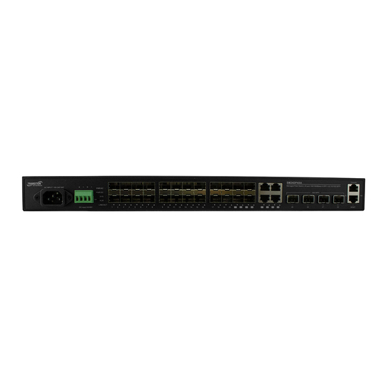
Front Panel
The SM24DP4XA front panel provides the ports, LEDs, buttons, and power inputs as shown and described below.
Connectors: Provides one Console Port, one Management port, twenty 100/1000 SFP slots, four 100/1000
SFP/RJ-45 Combo ports, and four 1G/10G SFP+ slots.
Console port: one RJ-45 Console port to connect to a PC or terminal for Command Line Interface (CLI) command
entry (e.g., a PC running Hyper Terminal, Tera Term, etc.).
MGMT port: Dedicated out-of-band Management Port. Provides one RJ-45 Console port to connect to a PC
Ethernet port to run the Web UI.
AC Input: 100-240 VAC: Connects the Power Cord.
DC Input: Dual +24/+48 VDC or -24V/-48V VDC.
LEDs
The front panel LEDs provide status as shown and described below.
AC/DC Power LED: Indicates if the switch is powered up correctly.
SYS (System) Status LED : Indicates if the system is ready.
Port Status LEDs : Indicate the current status of each port.
ALM LED : Indicates if the system is operating normally.
LINK/ACT LEDs : Port Status LEDs indicate if copper port is enabled, linked, and connection speed.
RST (Reset) button
By pressing the front panel RST (Reset) button for certain period of time, you can:
Reset the Switch : To reboot and get the switch back to the previous configuration settings saved. Press the RST
button for 2 ~ 7 seconds; the SYS LED will blink Green and the Port Status LED is Off.
Restore the Switch to Factory Defaults : To restore the original factory default settings back to the switch.
Press the RST button for 7 ~ 12 seconds; the SYS LED will blink Green and the Port Status LED is On.
Note: You can determine which task is being performed by reading the LED behaviors while pressing the Reset
button. Once the LED behaviors are correctly displayed, just release the button.
Grounding
The SM24DP4XA back panel provides the Ground Screw. ATTENTION: This case must be earth
grounded. No DC input may be earth grounded. Use Isolated Power Supply.
33768 Rev. B
https://www.transition.com
Page 1 of 4
Advertisement
Table of Contents

Related Manuals for Transition Networks SM24DP4XA


Summary of Contents for Transition Networks SM24DP4XA
- Page 1 Switch Config via Web & CLI, Troubleshooting, Regulatory & Compliance, & Service, Warranty & Tech Support. Front Panel The SM24DP4XA front panel provides the ports, LEDs, buttons, and power inputs as shown and described below. Connectors: Provides one Console Port, one Management port, twenty 100/1000 SFP slots, four 100/1000 SFP/RJ-45 Combo ports, and four 1G/10G SFP+ slots.
- Page 2 You can install or remove a mini-GBIC SFP/SFP+ module from an SFP/SFP+ port without having to power off the switch. Note: The SFP ports should use UL Listed Optional Transceiver product, Rated 3.3Vdc, Laser Class 1. See the SFP manual for specific cautions, warnings, and instructions. See the Transition Networks SFP page our full range of Optical Devices.
- Page 3 Two DC Power Supply options are available (ordered separately): 25131 for 48VDC and 25079 for 24VDC, 76.8Watts. See the Install Guide for details. The SM24DP4XA DC input is dual +24/+48 VDC or -24V/-48V VDC. 1. Insert the negative/positive DC wires into the + and - terminals, respectively.
- Page 4 LORSQUE LE CIRCUIT EST VIVANT OU À MOINS QUE LA ZONE NE SOIT LIBRE DE CONCENTRATIONS IGNIFIABLES. For More Information Related manuals are: SM24DP4XA Install Guide 33769, Web User Guide 33770, and CLI Reference 33771. For Transition Networks Drivers, Firmware, etc. go to the Product Support webpage (logon required).
Need help?
Do you have a question about the SM24DP4XA and is the answer not in the manual?
Questions and answers