Table of Contents
Advertisement
Quick Links
Advertisement
Table of Contents
Troubleshooting

Subscribe to Our Youtube Channel
Related Manuals for Transition Networks SM24TBT2DPA


Summary of Contents for Transition Networks SM24TBT2DPA
- Page 1 Transition Networks SM24TBT2DPA Install Guide SM24TBT2DPA Managed Gigabit Ethernet PoE++ Switch (24) 10/100/1000Base‐T Ports + (2) 100/1000Base‐X SFP/RJ‐45 Combo Ports Install Guide 33737 Rev. C 33737 Rev. C https://www.transition.com Page 1 of 39 ...
-
Page 2: Safety Warnings And Cautions
Transition Networks SM24TBT2DPA Install Guide Safety Warnings and Cautions These products are not intended for use in life support products where failure of a product could reasonably be expected to result in death or personal injury. Anyone using this product in such an application without express written consent of an officer of Transition Networks does so at their own risk, and agrees to fully indemnify Transition Networks for any damages that may result from such use or sale. Attention: this product, like all electronic products, uses semiconductors that can be damaged by ESD (electrostatic discharge). Always observe appropriate precautions when handling. NOTE: Emphasizes important information or calls your attention to related features or instructions. WARNING: Alerts you to a potential hazard that could cause personal injury. CAUTION: Alerts you to a potential hazard that could cause loss of data, or damage the system or equipment. SM24TBT2DPA Managed Gigabit Ethernet PoE++ Switch Install Guide, 33737 Rev. C Record of Revisions Rev Date Description of Changes A 6/25/18 Initial release at SW v6.54.2865 2018‐05‐10. B 8/15/18 Update the PoE budget and add note on IEC 60417‐6172 (2012‐09). C 12/7/18 Update default IP address. Trademark notice: All trademarks and registered trademarks are the property of their respective owners. All other products or service names used in this publication are for identification purposes only, and may be trademarks or registered trademarks of their respective companies. All other trademarks or registered trademarks mentioned herein are the property of their respective holders. ... -
Page 3: Table Of Contents
Transition Networks SM24TBT2DPA Install Guide Contents Safety Warnings and Cautions ........................... 2 Chapter 1 – Introduction............................ 5 Product Overview .............................. 5 Features ................................... 5 PoE Features ................................ 5 Benefits .................................. 6 Ordering Information ............................... 6 Specifications ................................ 6 Software Features .............................. 9 Manual Overview ..............................13 Related Manuals ..............................13 Front Panel ................................13 LED Descriptions ..............................14 Mode/Reset Button ............................16 Back Panel ................................16 Chapter 2 – Installing the Switch ........................ 17 Package Contents ..............................17 ... - Page 4 Transition Networks SM24TBT2DPA Install Guide Record Device and System Information .........................32 Device Label and Packaging Label ..........................33 Chapter 5 ‐ Regulatory and Safety Information .................... 34 Compliance and Safety Statements ........................34 High Risk Activities Disclaimer ..........................34 Declaration of Conformity .............................34 Cautions and Warnings ............................35 Electrical Safety Warnings ............................36 Chapter 6 ‐ Service, Warranty & Tech Support .................... 37 Warranty ................................37 Contact Us ................................38 33737 Rev. C https://www.transition.com ...
-
Page 5: Chapter 1 - Introduction
Transition Networks SM24TBT2DPA Install Guide Chapter 1 – Introduction Product Overview Transition Networks’ SM24TBTDPA switch is a high performance Layer 2 managed switch with 52 Gbps switching capacity. It provides (24) 10/100/1000 copper ports with IEEE 802.3bt PoE ++ capability and (2) additional 100/1000 dual speed SFP/RJ‐45 Combo ports. The SM24TBTDPA complies with the latest IEEE 802.3bt PoE++ standard and supplies up to 90 Watts per port. It can provide up to 1560 Watts PoE output with equipped the dual hot‐swappable power supplies. The embedded DMS (Device Management System) is designed to make it easy to use, install and manage IP Phones, IP Cameras, high power WAPs, or LED lightening for enterprise applications. The SM24TBT2DPA provides (24) 10/100/1000Base‐T + (2) 100/1000Base‐X SFP/RJ‐45 Combo ports and one RJ45 Console port, and includes (1) AC power supply and 19” rack mount brackets. Features Hot‐swappable dual power supply modules Support IPV4/IPV6 dual protocol stack Support Jumbo Frame up to 9K bytes Authentication – RADIUS, TACACS+ Security ‐ Support SSH v1/SSH v2/SSL Port based or tagged (802.1Q) VLAN, MAC based, Management VLAN and Private VLAN Edge DHCP Relay, DHCP Server L2/L3/L4 ACLs Support MAC ACL, IP standard/extended ACL LLDP (Link Layer Discovery Protocol) IEEE 802.3az Energy Efficiency IP Source Guard, Port Security PoE Features Compliant with IEEE 802.3bt PoE++ ... -
Page 6: Benefits
Transition Networks SM24TBT2DPA Install Guide Benefits Feature‐rich Ethernet Switch for Enterprise‐class: The switch delivers advanced functionality in a L2+ managed switch including Layer 3 static route, DHCP server, Ipv6 support, LLDP, etc. It also has comprehensive security features such as IP source guard and ACL to guard your network from unauthorized access. It builds on its market‐leading price/performance with L2+ Managed GbE PoE switch, to provide secure, reliable, simple enterprise or SMB deployments. Easy to Install, Configure and Troubleshoot by Device Management System: The DMS provides embedded functions to facilitate device management anytime and anywhere. Its user‐friendly interface helps you manage devices intuitively. It supports various IP device types (e.g. IP‐phone, IP‐camera, WiFi‐AP) to enhance manageability and save time and money during installation and maintenance stages. Lower TCO with Energy‐efficient Design: EEE is designed to help customers reduce power consumption and lower the TCO with Energy Efficient Ethernet (IEEE 802.3az) features for building a green Ethernet network environment. Power over Ethernet Design: PoE++ extends the IEEE PoE+ standard to double the power per port to 60 watts. It has options to power IP devices with features like Soft reboot (Non‐Stop PoE), Power scheduling, Power delay, PoE Auto Power Reset, and PoE configuration. Ordering Information SKU Description 24‐port Gigabit PoE++, 2‐port SFP/RJ‐45 Combo Managed Switch with 1 power supply (780 SM24TBT2DPA Watts) standard. PS‐AC‐920 Secondary AC Power Supply (920 Watts); Optional; sold separately. SFPs Optional SFP modules sold separately. See our Optical Devices webpage. Specifications Port Configuration Total Ports ... - Page 7 Transition Networks SM24TBT2DPA Install Guide Dimensions, Weight, Humidity Dimensions (WxDxH) Weight Operating Humidity Millimeters Inches Kilograms Pounds 10% to 90% 442 x 300 x 44 17.4 x 11.8 x 1.73 4.75 10.47 non‐condensing Voltage and Frequency AC Input Voltage and Frequency Voltage 100‐200 VAC Frequency 50~60 Hz Output Power 54VDC/780W per Module Voltage Power Redundancy, Failover, Dual Hot Swappable Power Supplies Maximum Power Consumption without PoE: 79 Watts with dual AC power modules ...
- Page 8 Transition Networks SM24TBT2DPA Install Guide Compliance Regulation Regulatory Agency FCC Part 15 Class A. Electromagnetic Emissions European Emission Standard EN55022/EN61000‐3 (EMC) Generic European Immunity Standard European health, safety, CE Marking environmental protection Safety IEC60950‐1, IEC 60417‐6172 (2012‐09) MTBF MTBF Environment 182,061 Hrs. GB, GC ‐ Ground Benign, Controlled 25.00°C 99,282 Hrs. GB, GC ‐ Ground Benign, Controlled 40.00°C 33737 Rev. C https://www.transition.com ...
-
Page 9: Software Features
Transition Networks SM24TBT2DPA Install Guide Software Features Layer 2 Switching Standard Spanning Tree 802.1d Spanning Tree Rapid Spanning Tree (RSTP) 802.1w Protocol (STP) Multiple Spanning Tree (MSTP) 802.1s Link Aggregation Control Protocol (LACP) IEEE 802.3ad Trunking Up to 13 groups Up to 16 ports per group Supports up to 4K VLANs simultaneously (out of 4096 VLAN IDs) Port‐based VLAN 802.1Q tag‐based VLAN MAC‐based VLAN VLAN Management VLAN Private VLAN Edge (PVE) Q‐in‐Q (double tag) VLAN Voice VLAN ... - Page 10 Transition Networks SM24TBT2DPA Install Guide Layer 3 Switching Ipv4 Unicast: Static routing Ipv4 Static Routing Ipv6 Unicast: Static routing Ipv6 Static Routing Security SSH secures Telnet traffic in or out of the switch; SSH v1 and v2 are supported Secure Shell (SSH) SSL encrypts the http traffic, allowing advanced secure access to the browser‐based Secure Sockets Layer (SSL) management GUI in the switch IEEE802.1X: RADIUS authentication, authorization and accounting, MD5 hash, guest VLAN, single/multiple host mode and single/multiple sessions IEEE 802.1X Supports IGMP‐RADIUS based 802.1X Dynamic VLAN assignment PVE (also known as protected ports) provides L2 isolation between clients in the same Layer 2 Isolation Private VLAN Edge VLAN. Supports multiple uplinks Locks MAC addresses to ports, and limits the number of learned MAC address ...
- Page 11 Transition Networks SM24TBT2DPA Install Guide Ingress policer Rate Limiting Egress shaping and rate control Per port Management DHCP Server Support DHCP server to assign IP to DHCP clients You can assign an IP address based on the switch port the device is connected to. This will speed up installations of IP cameras; cameras can be configured after they DHCP per Port are on the network. The per‐port assignment allows you to know which IP was assigned to which camera. Configure Link‐Local IP address to a different VLAN interface. The first IP interface entry (169.254.xx.xx) is for the default value (VLAN 1). A link‐local address is a unicast Link‐Local Address address having link‐only scope that can be used to reach neighbors. All interfaces on binding interface routers must have a link‐local address. Also, ADDRCONF requires that interfaces on hosts have a link‐local address. Event Notification via Syslog and/or SNMP Traps Event Notifications Event Notification with 8 Severity levels Remote Monitoring Embedded RMON agent supports RMON groups 1,2,3,9 (history, statistics, alarms, (RMON) and events) for enhanced traffic management, monitoring and analysis Traffic on a port can be mirrored to another port for analysis with a network analyzer Port Mirroring or RMON probe. Up to n‐1 (where n is the max number of Switch Ports) ports can be mirrored to single destination port. A single session is supported. ...
- Page 12 Transition Networks SM24TBT2DPA Install Guide HTTP/HTTPs; SSH DHCP Client/ DHCPv6 Client Cable Diagnostics Other Management Ping Syslog Telnet Client IPv6 Management Power over Ethernet (PoE) Port Configuration Supports per‐port PoE configuration function PoE Scheduling Supports per port PoE scheduling to turn on/off the PoE devices (PDs) Auto Power Reset APR checks the link status of PDs and reboots PDs if there are no responses The switch provides power to the PDs based on delay time when PoE switch boots up, Power Delay in order to protect switch from misuse of the PDs (soft Soft Boot Non‐Stop PoE feature lets you upgrade switch firmware or reboot while retaining PoE reboot) power to PDs 33737 Rev. C https://www.transition.com ...
-
Page 13: Manual Overview
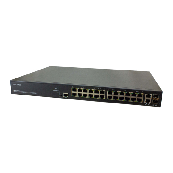
Transition Networks SM24TBT2DPA Install Guide Manual Overview This manual describes how to install, initially configure, and troubleshoot the SM24TBT2DPA Switch, including: Check the switch status by reading the LED behavior, Reset the switch or to restore the switch to factory defaults, Install the switch, Use a Web browser to initially configure the switch, and Troubleshoot the switch. Related Manuals A printed Quick Start Guide is shipped with each device. Other related manuals include: SM24TBT2DPA Quick Start Guide, 33736 SM24TBT2DPA Web User Guide, 33738 SM24TBT2DPA CLI Reference, 33739 Release Notes (version specific) For Transition Networks Drivers, Firmware, etc. go to the Product Support webpage (logon required). For Transition Networks Manuals, Brochures, Data Sheets, etc. go to the Support Library (no logon required). For SFP manuals see Transition Networks SFP webpage. Front Panel The SM24TBT2DPA front panel LEDs, ports and buttons are shown and described below. 33737 Rev. C https://www.transition.com ... -
Page 14: Led Descriptions
Transition Networks SM24TBT2DPA Install Guide LED Descriptions The LEDs on the front panel provide switch status checking and monitoring. The three types of LEDs are described below: SYS (System) LED: indicates if the switch is powered up correctly or indicates if there is a system alarm triggered for troubleshooting. System LED LED Color State Description On The switch is powered ON correctly. Green Off The switch is not receiving power. System An abnormal state, such as exceeding operating temperature Red On range, has been detected in the switch. Mode LEDs: indicate the mode of all RJ45/SFP ports on the switch. You can press the Mode button sequentially to switch among the two different modes (Link/Activity/Speed mode and PoE mode). Mode LEDs LED Color State Description The Port Status LEDs display link status, network activity and Link/Act/Speed Green On speed of each port. The RJ45 Port Status LEDs display PoE powering status of each PoE ... - Page 15 Transition Networks SM24TBT2DPA Install Guide Port Status LEDs: indicate the current status of each RJ45/SFP port. You can check these LEDs to understand the port status in different modes, after changing the mode by pressing Mode button. Press the MODE button for less than 2 seconds to change LED modes (Link/Act/Speed Mode or PoE Mode); you can then check the port status by reading the LED behaviors per the table below. Table 3: Port Status LEDs When Link/Act/Speed Mode LED Lit LED Color State Description The port is enabled and established a link to connected device, and the connection Green On speed is 1000Mbps. Green Blinking The port is transmitting/receiving packets, and the connection speed is 1000Mbps. The port is enabled and established a link to connected device, and the connection Amber On RJ45 speed is 10/100Mbps. Ports The port is transmitting/receiving packets, and the connection speed is Amber Blinking 10/100Mbps. The port has no active network cable connected, or it is not established a link to ‐‐ Off connected device. Otherwise, the port may have been disabled through the switch user interface. The port is enabled and established a link to connected device, and the connection Green On speed is 1000Mbps. ...
-
Page 16: Mode/Reset Button
Transition Networks SM24TBT2DPA Install Guide Mode/Reset Button Pressing the front panel Mode/Reset button for a period of time lets you perform these tasks: Change Port Status LED Mode: to read the port status correctly in the two different modes (Link/Act/Speed mode or PoE mode). Reset the Switch: to reboot and get the switch back to the previous configuration settings saved. Note that there is also a Non‐Stop PoE (soft reboot) feature allows the switch to reboot without affecting PoE port power via the Web UI or CLI. Restore the Switch to Factory Defaults: to restore the original factory default settings back to the switch. Note: Use the table below to determine which task is being performed by reading the LED behaviors while pressing and holding the Mode/Reset button. When the LED behavior displays correctly, release the button. Table 4: Mode/Reset Button Descriptions Task to Perform Press Button for SYS LED Behavior Port Status LED Behavior LED status will change based on the mode Change LED Mode 0 ~ 2 seconds ON Green selected. Reset the Switch 2 ~ 7 seconds Blinking Green ALL LEDs Off. Restore to Defaults 7 ~ 12 seconds Blinking Green ALL LEDs stay On. Back Panel The back panel provides for dual hot‐swappable 1560W power supplies for powering the switch. The switch ships ... -
Page 17: Chapter 2 - Installing The Switch
Transition Networks SM24TBT2DPA Install Guide Chapter 2 – Installing the Switch Package Contents Check the package contents to make sure you have received the following items. Contact your sales representative if any item is damaged or missing. Please save the packaging for possible future use. One SM24TBT2DPA Switch with single AC Power Supply Module One TN Postcard (33504) One Quick Start Guide (33736) One DB9F to RJ45 Cable (6WPDB92RJ453) Four Rubber Feet (6RR2005AB4B2) Two Brackets (6EFS226C0E09) Eight Screw s (6PF+UN3X5000) Note: The switch is an indoor device. If it is to be used with outdoor devices such as outdoor IP cameras or outdoor WiFi APs, then it is strongly suggested you install a surge protector or surge suppressor in order to protect the switch. Safety Instructions for Rack Mount Installations The instructions below (or similar) are intended for rackmount installation environments: 1. Elevated Operating Ambient: if installed in a closed or multi‐unit rack assembly, the operating ambient temperature of the rack environment may exceed room ambient. Install the equipment in an environment compatible with the maximum ambient temperature (Tma) specified. 2. Reduced Air Flow: install the equipment in a rack so that the amount of air flow required for safe operation is not compromised. 3. Mechanical Loading: Mount the equipment in the rack so that a hazardous condition does not occur due to ... -
Page 18: Mounting The Switch In A 19-Inch Rack
Transition Networks SM24TBT2DPA Install Guide Mounting the Switch in a 19‐inch Rack 1. Attach the mounting brackets to both sides of the chassis. Insert screws and tighten with a screwdriver to secure the brackets. 2. Place the switch on a rack shelf in the rack. Push it in until the oval holes in the brackets align with the mounting holes in the rack posts. 3. Attach the brackets to the posts. Insert screws and tighten them. Mounting the Switch on Desk or Shelf 1. Verify that the workbench is sturdy and reliably grounded. 2. Attach the four adhesive rubber feet to the bottom of the switch. 33737 Rev. C https://www.transition.com ... -
Page 19: Installing Sfp Modules
Transition Networks SM24TBT2DPA Install Guide Installing SFP Modules You can install or remove a mini‐GBIC SFP module from a SFP port without having to power off the switch. Note: The SFP ports should use UL Listed Optional Transceiver product, Rated 3.3Vdc, Laser Class 1. See the SFP manual for specific cautions, warnings, and instructions. See the Transition Networks SFP page for our full range of Optical Devices. During installation and maintenance, avoid direct exposure to laser beams. Specifically, do not look into laser ports. Ensure that each SFP port at which laser beams are (or will be) present is occupied by an SFP that is locked in position. Position the SFP device at either installation slot, with the SFP label facing up (Port 25) or down (Port 26). Carefully slide the SFP device into the slot, aligning it with the internal installation guides. Press firmly to ensure that the SFP device is firmly seated against the internal mating connector. Attach an appropriate cable into the SFP module port. Attach the other end of the cable to the other device. Note: Do not remove and replace the SFP modules more often than necessary; excessive SFP removing/replacing can shorten the SFPs useful life. Grounding ... -
Page 20: Power Supply Specifications
Transition Networks SM24TBT2DPA Install Guide Power Supply Specifications CAUTION! Hazardous Area: Do Not remove this cover. Trained service people only. No serviceable components inside. LEDs: DC OK and AC OK LEDs on front panel. See “Power Supply LEDs” on page 13. Dimensions (H x W x D): 1‐9/16” x 2‐13/16” x 8‐9/16” (25.4 m x 50.8 mm x 203.2 mm) Warranty: 5 years warranty for the PS‐AC‐920. Unpacking / Installing / Replacing Power Supplies The switch ships with one power supply (780 Watts) standard; order the second Power Supply (780 Watts) if the full 90 Watts output is needed on all ports. Unpacking Power Supply The optional second power supply is packed separately, if ordered. Unpack the optional second power supply and save the packaging for possible future use. 33737 Rev. C https://www.transition.com ... -
Page 21: Installing Power Supply
Transition Networks SM24TBT2DPA Install Guide Installing Power Supply CAUTION: Hot Surfaces. Warning: Class I Equipment. This equipment must be earthed. The power plug must be connected to a properly wired earth ground socket outlet. An improperly wired socket outlet could place hazardous voltages on accessible metal parts. Indicates shock hazards that result in serious injury or death if safety instructions are not followed. Disconnect all power sources; indicates to unplug all power cord(s) to disconnect AC power. Warning: Risk of electrical shock. For multiple power sources: Energy hazard if both power modules are not disconnected. Disconnect both power sources before servicing. Warning: Shock/damage hazard exists if power supply is installed / removed while powered on. 1. Remove all sources of power to the switch. 2. Refer to the “Grounding” section above. 3. Remove the blank Face Plate to use the one open Power Supply slot. Save the Face Plate and screws. 4. Carefully insert the Power Supply into the chassis until the Locking Lever clicks. 5. Fasten the AC Power Supply with the Mounting Screws (and Power Cord Retainer, if used). 6. Continue with “Connecting the AC Power Cord” on the next page. Caution: Shock hazard. Disconnect all power sources. Note: This product is to be connected only to UL listed PoE networks and without routing to the outside plant. 33737 Rev. C ... -
Page 22: Replacing Power Supply
Transition Networks SM24TBT2DPA Install Guide Replacing Power Supply Warning: Risk of electrical shock. For multiple power sources: Energy hazard if both power modules are not disconnected. Disconnect both power sources before servicing. Warning: Shock/damage hazard exists if power supply is installed / removed while powered on. 1. Remove all sources of power to the switch. 2. Refer to the “Grounding” section above. 3. Disconnect the AC power cord from the AC power outlet. 4. Disconnect the AC power cord from the switch AC power receptacle and Power Cord Retainer (if used). 5. Pinch the Pull Bar and the Locking Lever together and pull the old Power Supply from the chassis slot. 6. Carefully insert the new Power Supply into the chassis slot until the Locking Lever clicks. 7. Continue with “Connecting the AC Power Cord” below. Connecting the AC Power Cord 1. Connect the AC power cord to the switch AC power receptacle. 2. Use the Power Cord Retainer if desired. 3. Connect the other end of the AC power cord to live 3‐prong grounded AC power outlet. 4. Check the SYS LED. If it is On, the power connection is correct. 33737 Rev. C https://www.transition.com ... -
Page 23: Poe Vs. Poe+ Vs. Poe
Transition Networks SM24TBT2DPA Install Guide PoE vs. PoE+ vs. PoE++ PoE was first developed to power Voice over Internet Protocol (VoIP) phones. In 2001 and 2002, Wireless Access Point makers, and other manufacturers took advantage of the technique. Per IEEE 802.3af, PoE can use a single, standard RJ45 connector and CAT 5 (or even CAT 3) cable. PoE+ (PoE Plus) provides extended support for new end devices with higher power requirements. The IEE 802.3at standard provides up to 30 W of power to include newer end devices such as IEEE 802.11n wireless access points, surveillance cameras, etc. PoE++: As manufacturers advance the use of PoE, PoE++ became available for PoE with greater output. PoE++ delivers up to 60 watts of power using the same 802.3at standard. PoE++ is delivered using the simultaneous transmission of Mode A and Mode B. PoE++ is ideal for IP surveillance cameras that require more throughput or a various other equipment such as LCD displays, computer workstations, and biomedical equipment. Min. cable type Cat5e; recommend Cat 6A cabling. Higher categories have better PoE++ performance. The IEEE 802.3bt amendment to IEEE Std 802.3‐2015 increases the maximum PD power available by utilizing all four pairs in the specified structured wiring plant. This represents a substantial change to the capabilities of Ethernet with standardized power. The power classification information exchanged during negotiation is extended to allow meaningful power management capability. These enhancements provide higher power and more efficient standardized PoE delivery systems for applications such as VoIP phones, pan‐tilt‐zoom (PTZ) cameras with integrated fans and heating elements to operate at extreme temperatures, security card readers, LED lighting, POS equipment, thin clients, multi‐radio wireless access points, digital signage, building automation, industrial sensors/actuators, etc. See below for PoE++ type, class, and power descriptions. PD Type PD Power Cable Category Classes Type 3 40 – 51 W Cat5e 4 pairs class 5‐6 Type 4 62 – 71 W Cat5e 4 pairs class 7‐8 PoE/PoE+/PoE++ Comparison The table below compares the PoE types. ... -
Page 24: Chapter 3 - Initial Switch Configuration
Transition Networks SM24TBT2DPA Install Guide Chapter 3 ‐ Initial Switch Configuration Initial Switch Configuration via Web Browser After powering up the switch for the first time, you can perform the initial switch configuration using a web browser. For managing other switch features, see the Web User Guide for details. To begin with the initial configuration stage, you need to reconfigure your PC’s IP address and subnet mask so as to make sure the PC can communicate with the switch. After changing PC’s IP address (for example, 192.168.1.250), then you can access the Web interface of the switch using the switch’s default IP address as shown below. Note: The switch factory default IP address is 192.168.1.77. The factory default Subnet Mask is 255.255.255.0. 1. Power up the PC that you will use for the initial configuration. Please make sure the PC has the Ethernet RJ45 connector to be connected to the switch via standard Ethernet LAN cable. 2. Reconfigure the PC’s IP address and Subnet Mask as below, so that it can communicate with the switch. The method to change the PC’s IP address, for example, for a PC running Windows® 7/8.x/10, is: 2a: Type “network and sharing“ into the Search box in the Start Menu. 2b: Select Network and Sharing Center 2c: Click on Change adapter settings on the left of PC screen Note: You can skip step 2a to 2c, by pressing WinKey+R and type ”ncpa.cpl” command to get to step 2d directly. 2d: Right‐click on your local adapter and select Properties 2e: In the Local Area Connection Properties window highlight Internet Protocol Version 4 (TCP/IPv4) then click the Properties button. Note: Be sure to record all your PC’s current IP settings to be able to restore them later. 2f: Select the radio button Use the following IP address and enter in the IP for the PC (e.g. any IP address not in use, and between 192.168.1.78 and 192.168.1.254), Subnet mask (e.g. 255.255.255.0), and Default gateway that corresponds with your network setup. Then enter your Preferred and Alternate DNS server addresses. 2g: Click OK to change the PC’s IP address. 3. Power up the switch to be initially configured, and wait until it has finished its start‐up processes. 4. Connect the PC to any port on the switch using a standard Ethernet cable, and check the port LED on the switch to make sure the link status of the PC is OK. ... -
Page 25: Initial Switch Configuration Via Cli
Transition Networks SM24TBT2DPA Install Guide If your PC is configured correctly, the switch Login page displays as shown below. If you do not see the above login page, try these steps: ‐ Refresh the web page. ‐ Check to see if there is an IP address conflict. ‐ Clean browser cookies and temporary internet files. ‐ Check your PC settings again and repeat step 2. 6. Enter the factory default username (admin) and password (admin) on login page. 7. Click “Login” to log into the switch. See the Web User Guide for additional information. Initial Switch Configuration via CLI Use an RJ‐45 cable to connect a terminal or PC/terminal emulator to the switch port to access the CLI. Attach the RJ‐45 serial port on the switch front panel to the cable for Telnet/CLI configuration. Attach the other end of the DB‐9 cable to a PC running Telnet or a terminal emulation program such as HyperTerminal or TeraTerm. After powering up the switch for the first time, you can perform the initial switch configuration using the CLI (Command Line Interface). For managing other switch features, see the CLI Reference for details. 33737 Rev. C https://www.transition.com ... -
Page 26: Chapter 4 - Troubleshooting
Transition Networks SM24TBT2DPA Install Guide Chapter 4 ‐ Troubleshooting Basic Troubleshooting 1. Make sure your switch model supports the feature or function attempted; see Features on page 5 and check the Release Notes for your particular version. 2. Verify the install process; see Chapter 2 – Installing the Switch on page 17. 3. Verify the initial switch configuration; see Chapter 3 ‐ Initial Switch Configuration on page 24. 4. Troubleshoot connected network devices to pinpoint the problem to the switch. 5. Run the System Diagnostics (ping, cable diagnostics, traceroute). See the Web User Guide or the CLI Reference. 6. Reset the switch; see Mode/Reset Button on page 16. 7. Restore the switch to its factory default settings; see Mode/Reset Button on page 16. 8. If using the CLI, try configuring / testing via the Web UI and vice versa. See the Web User Guide or the CLI Reference. LED Summary Category LED Color Function LED Off: The switch is not receiving power. Global System/Alarm Green LED On: The switch is Powered On. LED Off: AC Power Supply or Normal Power Supply. Global ... -
Page 27: Led Troubleshooting
Transition Networks SM24TBT2DPA Install Guide LED Troubleshooting Use the table below to troubleshoot problems by taking actions based on the suggested solutions within. Table 5: Troubleshooting Symptom Possible Cause Suggested Solution 1. Check if correct power cord is connected firmly to the switch and to the AC outlet socket. SYSTEM LED is The switch is not 2. Cycle switch by unplugging and plugging the power cord back into Off receiving power. the switch. 3. If the LED is still off, try to plug power cord into a different AC outlet socket to make sure correct AC source is supplied. An abnormal Check the switch system log via the Web UI for any abnormal SYSTEM LED is state has been state (e.g. exceeding operating temperature range) and take RED detected by the corresponding actions to resolve. switch. 1. Check if the cable connector plug is firmly inserted and locked into Port Status LED is The port is not the port at both the switch and the connected device. Off in connected or the 2. Make sure the connected device is up and running correctly. ... -
Page 28: Troubleshooting Poe Problems
Transition Networks SM24TBT2DPA Install Guide Troubleshooting PoE Problems 1. Note that this product is to be connected only to UL listed PoE networks and without routing to the outside plant. 2. Note that PoE devices initially draw more power during their boot up sequence than during normal operation. 3. Determine what the requested power was at the time of failure. 4. Identify how long the device was up and what events may have occurred at the time of the error to help find the root cause (e.g., an IP phone that comes out of sleep and turns on fully may draw more power momentarily). 5. Determine if there is an issue with the PD drawing too much power; check the PD vendor documentation to determine why it exceeds the power it has negotiated with the switch. 6. Check the type and length of the cabling for any effect on the electrical characteristics and impact on the amount of power drawn on a port. 7. Investigate the power negotiation and confirm that the power requested by a device is also the amount of power that gets allocated. For example, using LLDP requires additional power budget for cabling between the PD and the PSE. 8. Use power measuring and testing equipment to determine if the PD overdraws the amount of power it gets allocated. 9. Enable CDP awareness via the Web UI or the CLI. CDP (Cisco Discovery Protocol) is a Cisco‐proprietary Layer 2 protocol that runs on most Cisco equipment and shares information about directly connected Cisco equipment. PoE switches with CDP enabled can recognize Cisco powered devices such as IP phones and WAPs. The actual power requirement can be advertised by the powered device, and the unused class power is returned to the switch power budget. 33737 Rev. C ... -
Page 29: Poe Modes And Compliance
Transition Networks SM24TBT2DPA Install Guide PoE Modes and Compliance PoE Deployment Environments A and B IEEE802.3at‐2009 defines two deployment environments in section 33.4.1: Environment A: when both PSE and PD are located indoors, inside the same building. In this environment, there has to be electrical isolation between the PoE circuitry and the data circuitry inside a PSE. Multi‐port PSE’s can all share the same ground isolation. Environment A is therefore an indoor PSE – indoor PD environment (a.k.a. indoor/indoor). Environment B: when the PSE and PD are not located in the same building. In this environment there needs to be electrical isolation between PoE and data, as well as between every port in a multi‐port PSE. This isolation between ports requirement de facto determines a completely separate power supply per port, which makes multi‐port PSE’s for outdoor PD deployment impractical. Environment B is therefore an indoor PSE ‐ outdoor PD (a.k.a. indoor/outdoor) or outdoor PSE‐outdoor PD (a.k.a. outdoor/outdoor) environment. This means only single‐port PSE’s should normally be used when PD’s are deployed outdoors. In summary, the PD‐PSE environment is one of these three combinations: 1. PoE Source is indoor, PD is indoor (Env. A) 2. PoE Source is indoor, PD is outdoor (Env. B) 3. PoE Source is outdoor, PD is outdoor (Env. B) Option 3 is the most challenging environment since both the PD and PSE are installed outdoors. Caution: The switch is an indoor device. If it is to be used with outdoor devices such as outdoor IP cameras or outdoor Wi‐Fi APs, then you are strongly suggested to install a surge protector or surge suppressor in order to protect the switch. The switch is compliant with 802.3at in Environment A when using an isolated power supply. For 802.3at Environment B applications, i.e. building to building, copper to copper endpoint connections: 1) use an Ethernet network isolator module (PoE disabled), or 2) use mid‐span injector(s) such as Transition Networks’ MIL‐L100i or L1000i‐at, between this switch’s PSE port and link partner PD port. Mode A vs. Mode B Alternative A, also known as Mode A, uses the data pairs of an Ethernet link to deliver power. Data Pairs include pins 1,2 and 3,6. PSEs using Mode A supply a positive voltage to pins 1 and 2. Alternative B, also known as Mode B, uses the spare pairs to deliver power. Spare Pairs include pins 4,5 and 7,8. 802.3af/at Standard “compliant” vs "compatible" PDs Knowing the difference between PoE "compliant" devices and "compatible" devices can help avoid interoperability and connectivity issues. Compliant and compatible PoE devices are not held to the same 802.3af/at standard: ... - Page 30 Transition Networks SM24TBT2DPA Install Guide Typical PD Power Requirements □ 1.8 Watts: Transition Networks’ M/GE‐ISW‐SFP‐01‐PD (Class 1 Powered Device (0.44 Watts ‐ 3.84 Watts). □ 13W: IP Camera, VoIP Phone, Wireless Access Point, Networked Audio. □ 30W: IP Telephone, WiMAX Access Point, PTZ Camera, Remote Computer Terminal. □ 60W : Door Access System, Video Phone, Thin Client. □ 100W: Digital Signage Display, Point‐of‐Sale System, LCD TV, Computer Monitor. □ 200W: Larger TV, Larger Display, Larger Monitor, Laptop. After eliminating basic network factors, ask your PD vendor for the PD’s power supply mode and polarities supported and exact power consumption. VoIP vs SIP VoIP (Voice over IP) involves making or receiving phone calls over the Internet or internal networks. SIP (Session Initiation Protocol) is an application layer protocol used to establish, modify, and terminate multimedia sessions such as VoIP calls. One difference is their scope. VoIP is not a discrete technology; it is a set of technologies used in modern telecom networks. SIP is a signaling protocol used within VoIP technology. Another difference is that VoIP sends only voice messages, while SIP can carry all media forms (not just voice messages). Mixing POE and Non‐POE Devices You can mix POE and non‐POE devices on the same POE switch (i.e., you can put PCs on the same POE switch as a SIP phone or a VOIP phone). The PSE (your switch) will only send power if requested by the PD. Ethernet and PoE Intra‐Building Cabling Warnings 1. Ethernet cables are intended for intrabuilding use only. Connecting your TN switch directly to Ethernet cables that run outside the building in which the switch is housed will void the user's warranty and could create a fire or shock hazard. ...
- Page 31 Transition Networks SM24TBT2DPA Install Guide PoE ++ Connectivity, Arcing, and Temperature Issues PoE is not live until powered device (PD) and powered sourcing equipment (PSE) handshake. When unplugging live PoE, an arc (or spark) occurs between plug and jack contacts. Arcing occurs with ALL mated PoE connections. Ensure jack meets IEC 60512‐99‐001 for compliance. Ambient jack temperature must be 5 deg. C below maximum jack operating temperature. To operate in 60 deg. C ambient, you need a 65 deg. C rated jack. See the BICSI webpage for your particular type of PoE (e.g., for PoE++). See the ANSI/NECA/BICSI 568‐2006 Standard for Installing Commercial Building Telecommunications Cabling. ANSII/NECA/BICSI 568 describes minimum requirements and procedures for installing the infrastructure for telecoms, including balanced twisted‐pair copper cabling and optical fiber cabling that transport telecommunications signals (e.g., voice, data, and video). The 2008 NEC standard is a safety code widely adopted in the USA as minimum required safety rules for the electrical industry. The 2008 NEC points to the ANSII/NECA/BICSI 568 standard as a best practices source document. 33737 Rev. C https://www.transition.com ...
-
Page 32: Record Device And System Information
Describe any action(s) already taken to resolve the problem (e.g., changing mode, rebooting, etc.): ________________ ________________________________________________________________________________________________________________________ ________________________________________________________________________________________________________________________ ________________________________________________________________________________________________________________________ The serial and revision numbers of all involved Transition Networks products in the network: ______________________ ________________________________________________________________________________________________________________________ ________________________________________________________________________________________________________________________ Describe your network environment (layout, cable type, etc.): ________________________________________________________... -
Page 33: Device Label And Packaging Label
Transition Networks SM24TBT2DPA Install Guide Device Label and Packaging Label In addition to the device CLI and Web GUI, you can find device information on the device serial Label (left) and box serial Label (right). Device Serial Label Box Serial Label 33737 Rev. C https://www.transition.com ... -
Page 34: Chapter 5 - Regulatory And Safety Information
Transition Networks SM24TBT2DPA Install Guide Chapter 5 ‐ Regulatory and Safety Information Compliance and Safety Statements FCC, Class A: This product has been tested and found to comply with the limits for a Class A digital device pursuant to Part 15 of the FCC Rules. These limits are designed to provide reasonable protection against harmful interference when the equipment is operated in a commercial environment. This product generates, uses, and can radiate radio frequency energy and, if not installed and used in accordance with the manufacturer’s instruction manual, may cause harmful interference with radio communications. Operation of this product in a residential area is likely to cause harmful interference, in which case you will be required to correct the interference at your own expense. This device complies with Part 15 of the FCC Rules. Operation is subject to the following two conditions: 1) This device may not cause harmful interference. 2) This device must accept any interference received, including interference that may cause undesired operation. CE MARK DECLARATION OF CONFORMANCE FOR EMI AND SAFETY (EEC): This equipment has been tested and found to comply with the protection requirements of European Emission Standard EN55022/EN61000‐3 and the Generic European Immunity Standard EN55024. High Risk Activities Disclaimer Components, units, or third‐party products used in the product described herein are NOT fault‐tolerant and are NOT designed, manufactured, or intended for use as on‐line control equipment in the following hazardous environments requiring fail‐safe controls: the operation of Nuclear Facilities, Aircraft Navigation or Aircraft Communication Systems, Air Traffic Control, Life Support, or Weapons Systems ("High Risk Activities"). Transition Networks and its supplier(s) specifically disclaim any expressed or implied warranty of fitness for such High Risk Activities. Declaration of Conformity 33737 Rev. C https://www.transition.com ... -
Page 35: Cautions And Warnings
Transition Networks SM24TBT2DPA Install Guide Cautions and Warnings Definitions Cautions indicate that there is the possibility of poor equipment performance or potential damage to the equipment. Warnings indicate that there is the possibility of injury to person. Cautions and Warnings appear here and may appear throughout this manual where appropriate. Failure to read and understand the information identified by this symbol could result in poor equipment performance, damage to the equipment, or injury to persons. Cautions While installing or servicing the power module, wear a grounding device and observe all electrostatic discharge precautions. Failure to observe this caution could result in damage to, or failure of the power module. Warnings Warning: Do not connect the power module to an external power source before installing it into the chassis. Failure to observe this warning could result in an electrical shock, even death. WARNING: The power module has a provision for grounding. Equipment grounding is vital to ensure safe operation. The installer must ensure that the power module is properly grounded during and after installation. Failure to observe this warning could result in an electric shock, even death. WARNING: A readily accessible, suitable National Electrical Code (NEC) or local electrical code approved disconnect device and branch‐circuit protector must be part of the building's installed wiring to accommodate permanently connected equipment. Failure to observe this warning could result in an electric shock, even death. WARNING: Turn the external power source OFF and ensure that the power module is disconnected from the external power source before performing any maintenance. Failure to observe this warning could result in an electrical shock, even death. WARNING: Ensure that the disconnect device for the external power source is OPEN (turned OFF) before disconnecting or connecting the power leads to the power module. Failure to observe this warning could result in an electric shock, even death. ... -
Page 36: Electrical Safety Warnings
Transition Networks SM24TBT2DPA Install Guide Electrical Safety Warnings Electrical Safety IMPORTANT: This equipment must be installed in accordance with safety precautions. Elektrische Sicherheit WICHTIG: Für die Installation dieses Gerätes ist die Einhaltung von Sicherheitsvorkehrungen erforderlich. Elektrisk sikkerhed VIGTIGT: Dette udstyr skal installeres i overensstemmelse med sikkerhedsadvarslerne. Elektrische veiligheid BELANGRIJK: Dit apparaat moet in overeenstemming met de veiligheidsvoorschriften worden geïnstalleerd. Sécurité électrique IMPORTANT: Cet équipement doit être utilisé conformément aux instructions de sécurité. Sähköturvallisuus TÄRKEÄÄ: Tämä laite on asennettava turvaohjeiden mukaisesti. Sicurezza elettrica IMPORTANTE: questa apparecchiatura deve essere installata rispettando le norme di sicurezza. Elektrisk sikkerhet VIKTIG: Dette utstyret skal installeres i samsvar med sikkerhetsregler. Segurança eléctrica IMPORTANTE: Este equipamento tem que ser instalado segundo as medidas de precaução de segurança. Seguridad eléctrica IMPORTANTE: La instalación de este equipo deberá llevarse a cabo cumpliendo con las precauciones de seguridad. Elsäkerhet OBS! Alla nödvändiga försiktighetsåtgärder måste vidtas när denna utrustning används. 33737 Rev. C https://www.transition.com ... -
Page 37: Chapter 6 - Service, Warranty & Tech Support
Transition Networks SM24TBT2DPA Install Guide Chapter 6 ‐ Service, Warranty & Tech Support Warranty Limited Lifetime Warranty Effective for Products Shipped May 1, 1999 and After. Every Transition Networks labeled product purchased after May 1, 1999, and not covered by a fixed‐duration warranty will be free from defects in material and workmanship for its lifetime. This warranty covers the original user only and is not transferable. This warranty does not cover damage from accident, acts of God, neglect, contamination, misuse or abnormal conditions of operation or handling, including over‐voltage failures caused by use outside of the product’s specified rating, or normal wear and tear of mechanical components. Transition Networks will, at its option: • Repair the defective product to functional specification at no charge • Replace the product with an equivalent functional product • Refund a portion of purchase price based on a depreciated value To return a defective product for warranty coverage, contact Transition Networks’ Customer Support for a return authorization number. Send the defective product postage and insurance prepaid to the following address: Transition Networks, Inc. 10900 Red Circle Drive Minnetonka, MN 55343 USA Attn: RETURNS DEPT: CRA/RMA # ___________ Failure to properly protect the product during shipping may void this warranty. The return authorization number must be written on the outside of the carton to ensure its acceptance. We cannot accept delivery of any equipment that is sent to us without a CRA or RMA number. CRA’s are valid for 60 days from the date of issuance. An invoice will be generated for payment on any unit(s) not returned within 60 days. Upon completion of a demo/ evaluation test period, units must be returned or purchased within 30 days. An invoice will be generated for payment on any unit(s) not returned within 30 days after the demo/ evaluation period has expired. ... -
Page 38: Contact Us
Transition Networks SM24TBT2DPA Install Guide Transition Networks reserves the right to charge a $50 fee for all testing and shipping incurred, if after testing, a return is classified as “No Problem Found.” THIS WARRANTY IS YOUR ONLY REMEDY. NO OTHER WARRANTIES, SUCH AS FITNESS FOR A PARTICULAR PURPOSE, ARE EXPRESSED OR IMPLIED. TRANSITION NETWORKS IS NOT LIABLE FOR ANY SPECIAL, INDIRECT, INCIDENTAL OR CONSEQUENTIAL DAMAGES OR LOSSES, INCLUDING LOSS OF DATA, ARISING FROM ANY CAUSE OR THEORY. AUTHORIZED RESELLERS ARE NOT AUTHORIZED TO EXTEND ANY DIFFERENT WARRANTY ON TRANSITION NETWORKS’S BEHALF. Contact Us Technical Support: Technical support is available 24‐hours a day US and Canada: 1‐800‐260‐1312 International: 00‐1‐952‐941‐7600 Main Office tel: +1.952.941.7600 | toll free: 1.800.526.9267 | fax: 952.941.2322 sales@transition.com | techsupport@transition.com | customerservice@transition.com Address Transition Networks 10900 Red Circle Drive Minnetonka, MN 55343, U.S.A. Web: https://www.transition.com ... - Page 39 Transition Networks SM24TBT2DPA Install Guide Transition Networks 10900 Red Circle Drive Minnetonka, MN 55343 USA tel: +1.952.941.7600 | toll free: 1.800.526.9267 | fax: 952.941.2322 Copyright© 2018 Transition Networks. All rights reserved. Printed in the U.S.A. SM24TBT2DPA Managed Gigabit Ethernet PoE++ Switch Install Guide, 33737 Rev. C ...
Need help?
Do you have a question about the SM24TBT2DPA and is the answer not in the manual?
Questions and answers