Table of Contents
Advertisement
Quick Links
Advertisement
Table of Contents

Related Manuals for Keysight N432A


Summary of Contents for Keysight N432A
- Page 1 Keysight N432A Thermistor Power Meter Installation Guide...
- Page 2 Conformity. understood and met. where in the EULA. Keysight shall be under no obligation to update, revise or otherwise modify the Software. With WARNING respect to any technical data as defined by FAR 2.101, pursuant to FAR...
-
Page 3: Certification
Keysight shall not be liable for errors or for incidental or consequential damages in connection with the furnishing, use, or performance of this document or any information contained herein. -
Page 4: Limitation Of Warranty
Buyer. Keysight does not warrant the Buyer’s circuitry or malfunctions of Keysight products that result from the Buyer’s circuitry. In addition, Keysight does not warrant any damage that occurs as a result of the Buyer’s circuit or any defects that result from Buyer-supplied products. -
Page 5: Safety Symbols
Observe ESD precautions given on the pressed. To isolate the instrument, the product, or its user documentation, mains coupler (mains input cord) when handling equipment bearing this should be removed from the power mark. supply. Keysight N432A Installation Guide... -
Page 6: Safety Considerations
Failure to comply with these precautions or with specific warnings elsewhere in this manual violates safety standards for design, manufacture, and intended use of the instrument. Keysight Technologies assumes no liability for the customer’s failure to comply with these requirements. - Page 7 REMOVE POWER and do not use the product until safe operation can be verified by service-trained personnel. If necessary, return the product to Keysight for service and repair to ensure the safety features are maintained. – Do not substitute parts or modify equipment. Because of the danger of introducing additional hazards, do not install substitute parts or perform any unauthorized modification to the product.
-
Page 8: Environmental Conditions
Environmental Conditions The N432A is designed for indoor use and in an area with low condensation. The table below shows the general environmental requirements for this instrument. Environmental cond ition Requirement Operating condition – 0 °C to 45 °C Temperature Storage condition –... -
Page 9: Ventilation And Cleaning
Ventilation requirements To provide adequate ventilation, an air gap of approximately 75 mm (3 in.) should be maintained around the vented sections of the N432A. Cleaning Use a soft, lint- free, slightly dampened cloth to wipe the front- panel and side covers. -
Page 10: Compliance And Markings
– Australia/New Zealand: AS/NZS CISPR11:2004 Safety This product conforms to the requirements of the following safety standards: – IEC 61010- 1:2001/EN 61010- 1:2001 – Canada: CAN/CSA- C22.2 No. 61010- 1- 04 – USA: ANSI/UL 61010- 1:2004 Keysight N432A Installation Guide... -
Page 11: Sound Emission
Manufacturers declaration This statement is provided to comply with the requirements of the German Sound DIN 45635 T. 19 (Typprufung). Sound Pressure LpA < 70 dB. At operator position. Normal operation. According to ISO 7779 (Type Test). Keysight N432A Installation Guide... -
Page 12: Responsibilities Of The Customer
– access to and use of all information and facilities determined necessary by Keysight to service and/or maintain the products. (Insofar as these items may contain proprietary or classified information, the customer shall assume full responsibility for safeguarding and protection from wrongful use.) –... -
Page 13: Regulatory Markings
WEEE Directive (2002/96/EC) marking The RCM mark is a registered requirement. This affixed product label trademark of the Australian indicates that you must not discard Communications and Media Authority. this electrical or electronic product in domestic household waste. Keysight N432A Installation Guide... -
Page 14: Waste Electrical And Electronic Equipment (Weee) Directive 2002/96
To return this unwanted instrument, contact your nearest Keysight Service Center, or visit http://about.keysight.com/en/companyinfo/environment/takeback.shtml for more information. Sales and Technical Support To contact Keysight for sales and technical support, refer to the support links on the following Keysight websites: – www.keysight.com/support/N432A (product-specific information and support, software and documentation updates) –... -
Page 15: Table Of Contents
..........24 Keysight N432A Installation Guide... - Page 16 ....... . 49 Rack mounting a single N432A (using the Option 908 rack mount kit)
- Page 17 .....45 Figure 1-5 Changing the GPIB address .....48 Keysight N432A Installation Guide...
- Page 18 THIS PAGE HAS BEEN INTENTIONALLY LEFT BLANK. Keysight N432A Installation Guide...
-
Page 19: Getting Started
Keysight N432A Thermistor Power Meter Installation Guide Getting Started Introduction Documentation Information Overview Conventions Used in This Guide Sensor Compatibility Adjusting the Carrying Handle Front Panel Outlook Rear Panel Connections Turning On the N432A Connecting a Thermistor Sensor Remote Interface Configurations... -
Page 20: Introduction
If any damage is found, notify the nearest Keysight Sales Office immediately. Keep the original packaging in case the N432A has to be returned to Keysight in future. If you return the N432A for service, attach a tag identifying the owner and model number. -
Page 21: Documentation Information
Option 0BF. There is also a Connectivity Guide available on the Keysight IO Libraries Suite CD-ROM as a PDF file. This guide helps you to configure your N432A over GPIB, LAN, and USB remote interfaces. Keysight N432A Installation Guide... -
Page 22: Overview
– rack mounting the N432A – general specifications – compliance and markings – regulatory information – responsibilities of the customer For more detailed operating information, refer to the N432A Thermistor Power Meter User’s Guide and Programming Guide. Keysight N432A Installation Guide... -
Page 23: Conventions Used In This Guide
Conventions Used in This Guide The following conventions are used throughout this guide. This symbol and text represents a labeled key on the N432A front panel This symbol and text represents a labeled softkey, and is used to indicate that you... -
Page 24: Adjusting The Carrying Handle
Getting Started Adjusting the Carrying Handle Adjust the carrying handle to carry the N432A or to view the display. The carrying handle can be locked into three different positions. Pull the handle outwards, rotate it to the required position, and release it into one of the three locks. -
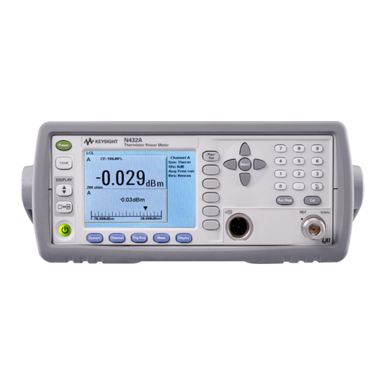
Page 25: Front Panel Outlook
Function Press this key to preset the N432A to its default state Press this key to control the N432A from the front panel when it is operating via the remote interfaces (when Local Lock Out is disabled) Press this key to select the upper or lower measurement window. The selected window is highlighted by a blue line on the right of the window. - Page 26 Press this key to access the measurement display menu. You can select the displayed measurement resolution, unit, and display format. Use this key together with to configure measurement displays. Keysight N432A Installation Guide...
- Page 27 For example, a 1 of 2 is displayed beside the key indicating the first page of a two-page menu. Press the key to access the next page or the second page (a 2 of 2 is displayed). Keysight N432A Installation Guide...
- Page 28 Press this key to access the zeroing menu Press this key to reset the MAX HOLD and MIN HOLD measurements Press these keys to enter numeric values in the pop-up fields, for example, the offset values. To complete the entry, use the softkey. Keysight N432A Installation Guide...
- Page 29 8478B thermistor sensor and meter system. The yellow LED beside the connector is lit when turned on. Thermistor mount input connector for 1.5 m, 3 m, and 6.1 m cables that connect to the 478A and 8478B thermistor sensors Keysight N432A Installation Guide...
-
Page 30: Rear Panel Connections
Recorder output connection is made via a BNC connector. This output produces a DC voltage that corresponds to the power level of the channel input. AC inlet The N432A has an autoconfiguring power supply. This allows it to operate over a range of voltages without manually being set to a certain voltage. and V... -
Page 31: Turning On The N432A
Getting Started Turning On the N432A You can turn on the N432A without connecting a thermistor sensor or a thermistor sensor cable. The N432A has an autoranging power supply. Ensure the supplied voltage is NOTE within the range of 100 Vac to 240 Vac and 50 Hz to 60 Hz and 400 Hz. - Page 32 Getting Started 3 Turn on the N432A and confirm that the background LED is yellow. 4 The N432A will power up within ~25 seconds, and you should see the following display: 5 The N432A is now ready for use. If the...
- Page 33 – Check that power is supplied to the N432A The red LED is not lit – Check the N432A fuses (refer to Step 6 below) If there is any self-test failure, the N432A is defective. Contact the Sel f-test(s)fails nearest Keysight Service Center (refer to “Sales and Technical...
-
Page 34: Connecting A Thermistor Sensor
Using a Keysight thermistor sensor cable, any Keysight 478A or 8478B thermistor sensor can be connected to the N432A. Follow the procedure below to connect a thermistor sensor to the N432A: 1 Connect one end of the thermistor sensor cable to the sensor. - Page 35 RF source. Press Confirm once you have verified that there is no RF source connected. 7 Zeroing will start automatically. The Zeroing pop-up message will be displayed during the zeroing process, Keysight N432A Installation Guide...
-
Page 36: Remote Interface Configurations
Only one interface should be used at any one time. To connect the N432A to your PC, configure and verify the connection, you can use the Keysight IO Libraries Suite or an equivalent. – To install the Keysight IO Libraries Suite, follow the instructions in the Keysight Automation-Ready CD with Keysight IO Libraries Suite provided with the standard purchase of the N432A. -
Page 37: Usb
Keysight IO Libraries software. If you have installed other I/O software, refer to the documentation that accompanies the software. 1 After the I/O software has been installed on your PC, connect the N432A to your PC using the supplied Type A – Mini 5-pin USB cable. - Page 38 4 You can use the Connection Expert in the IO Libraries Suite to check the instrument identification. 5 Now, you can use various programming environments to control the N432A. For an overview on programming the N432A via USB, refer to the connectivity guide and the programming guide. Keysight N432A Installation Guide...
-
Page 39: Lan
– An isolated (non-site) LAN is defined as a local area network (LAN) in which PCs and LAN-enabled instruments are not connected to a site LAN. Select the LAN network type you will use to connect the N432A to your PC. Then, follow the procedure that corresponds to your selected LAN network type. -
Page 40: Figure 1-2 Enabling Dhcp
If the DHCP server cannot be found on your network, the N432A will return to NOTE the auto IP mode, then static mode. 1 Using a standard LAN patch cable, connect both the PC and the N432A to LAN outlets. 2 Turn on the N432A. -
Page 41: Figure 1-3 Lan Network Restart Pop-Up
7 If you intend to program over the LAN interface, make sure that you have installed the I/O software on your PC. 8 Use the Connection Expert utility of the IO Libraries Suite to add the N432A and verify the connection. When identifying the N432A, it is easiest to use the IP address that you noted in step 5 above. - Page 42 7 If you intend to program over the LAN interface, make sure that you have installed the I/O software on your PC. 8 Use the Connection Expert utility of the IO Libraries Suite to add the N432A and verify the connection.
-
Page 43: Figure 1-4 Lan Network Manual Setup
In static mode, you must set up the IP address, subnet mask, default gateway, and DNS servers that are compatible with your network infrastructure. If they are not set up correctly, the N432A will not be visible on your network. Turn on the N432A. - Page 44 7 If you intend to program over the LAN interface, make sure that you have installed the I/O software on your PC. 8 Use the Connection Expert utility of the IO Libraries Suite to add the N432A and verify the connection.
-
Page 45: Gpib
N432A via GPIB. Changing the GPIB address The GPIB address is an integer between 0 and 30. The N432A is shipped with a default address of 10. The GPIB address is stored in a non-volatile memory. GPIB address 21 cannot be used as Keysight GPIB interface card default address NOTE is 21. -
Page 46: Figure 1-5 Changing The Gpib Address
3 Press the Select key and use the numeric keys to enter the GPIB address in the pop-up dialog. 4 Press Enter. Changing the GPIB address remotely You can set/query the GPIB address remotely using the following command: SYSTem:COMMunicate:GPIB:ADDRess Keysight N432A Installation Guide... -
Page 47: Rack Mounting The N432A
– An adequately rated switch (250 V, 10 A) or a circuit breaker (250 V, 5 A) shall be included in the rack. – It should be in close proximity to the N432A and within easy reach of the operator. -
Page 48: Rack Mounting A Single N432A (Using The Option 908 Rack Mount Kit)
Getting Started Rack mounting a single N432A (using the Option 908 rack mount kit) 1 Remove the carrying handle. 2 Remove the front and rear rubber bumpers. Keysight N432A Installation Guide... - Page 49 Getting Started 3 Fit the rack mount flanges. (Parts available separately: 5063-9240) 4 Ready for installation. Keysight N432A Installation Guide...
-
Page 50: Rack Mounting Two N432As Together (Using The Option 909 Rack Mount Kit)
Getting Started Rack mounting two N432As together (using the Option 909 rack mount kit) 1 Remove the carrying handle. 2 Remove the front and rear rubber bumpers. Keysight N432A Installation Guide... - Page 51 Getting Started 3 The hardware below is required to link the N432As together. 4 Fit a small rack mount flange to the opposite sides of each N432A. (Parts available separately: 5061-9694 and 5063-9212) 5 Fit two front linking plates to each N432A.
- Page 52 Getting Started 6 Engage the linking plates at the front of the N432As. 7 Attach the rear linking brackets. 8 Ready for installation. Keysight N432A Installation Guide...
-
Page 53: Characteristics And Specifications
Keysight N432A Thermistor Power Meter Installation Guide Characteristics and Specifications For the characteristics and specifications of the N432A Thermistor Power Meter, refer to the datasheet at http://literature.cdn.keysight.com/litweb/pdf/5990-5740EN.pdf. - Page 54 Characteristics and Specifications THIS PAGE HAS BEEN INTENTIONALLY LEFT BLANK. Keysight N432A Installation Guide...
- Page 55 This information is subject to change without notice. Always refer to the English version at the Keysight website for the latest revision. © Keysight Technologies 2010-2017 Edition 5, December 1, 2017 Printed in Malaysia *N432A-90000* N432A-90000 www.keysight.com...
Need help?
Do you have a question about the N432A and is the answer not in the manual?
Questions and answers