Table of Contents
Advertisement
Quick Links
Advertisement
Table of Contents

Related Manuals for Keysight N432A


Summary of Contents for Keysight N432A
- Page 1 Keysight N432A Thermistor Power Meter Service Guide...
- Page 2 Conformity. understood and met. where in the EULA. Keysight shall be under no obligation to update, revise or otherwise modify the Software. With WARNING respect to any technical data as defined by FAR 2.101, pursuant to FAR...
-
Page 3: Certification
Exclusive Remedies To the extent allowed by local law, the remedies provided herein are the Buyer’s sole and exclusive remedies. Keysight shall not be liable for any direct, indirect, special, incidental, or consequential damages (including lost profit or data), whether based on warranty, contract, tort, or any other legal theory. -
Page 4: Equipment Operation
For continued protection against fire, replace the line fuse(s) only with fuses of the same type and rating (for example, normal blow, time delay, and so on). The use of other fuses or material is prohibited. Keysight N432A Service Guide... -
Page 5: Safety Symbols
Equipment protected throughout by Earth (ground) terminal double insulation or reinforced insulation Protective earth (ground) terminal Frame or chassis (ground) terminal In position of a bi-stable push control Out position of a bi-stable push control Equipotentiality Keysight N432A Service Guide... -
Page 6: Safety Considerations
Failure to comply with these precautions or with specific warnings elsewhere in this manual violates safety standards for design, manufacture, and intended use of the instrument. Keysight Technologies assumes no liability for the customer’s failure to comply with these requirements. -
Page 7: Environmental Conditions
Environmental Conditions The N432A is designed for indoor use and in an area with low condensation. The table below shows the general environmental requirements for this instrument. Environmental cond ition Requirement Operating condition – 0 °C to 45 °C Temperature Storage condition –... -
Page 8: Regulatory Information
N432A. The N432A will self- recover and operate to all specifications when the source of ambient EM fields and noise are removed or when the N432A is protected from the ambient EM fields or when the N432A cabling is shielded from the ambient EM noise. -
Page 9: Regulatory Markings
Control and Laboratory Use and has been supplied in a safe condition. The instruction documentation contains information and warnings which must be followed by the user to ensure safe operation and to maintain the instrument in a safe condition. Keysight N432A Service Guide... -
Page 10: Waste Electrical And Electronic Equipment (Weee) Directive 2002/96/ Ec
To return this unwanted instrument, contact your nearest Keysight Service Center, or visit http://about.keysight.com/en/companyinfo/environment/takeback.shtml for more information. Sales and Technical Support To contact Keysight for sales and technical support, refer to the support links on the following Keysight websites: – www.keysight.com/support/N432A (product-specific information and support, software and documentation updates) –... -
Page 11: Table Of Contents
....... . .10 N432A at a Glance Front Panel Outlook . - Page 12 Checking the Power Line Fuses ....... 53 Specifications and Characteristics Keysight N432A Service Guide...
- Page 13 ....... . .40 Figure 3-2 Connecting 8482A to N432A for 1 mW power reference level test .
- Page 14 THIS PAGE HAS BEEN INTENTIONALLY LEFT BLANK. Keysight N432A Service Guide...
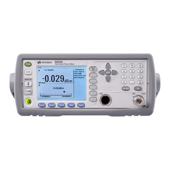
- Page 15 Keysight N432A Thermistor Power Meter Service Guide N432A at a Glance Front Panel Outlook Rear Panel Connections Display Layout This chapter provides an overview of the N432A front and rear panel outlook as well as its display layout.
-
Page 16: N432A At A Glance
Function Press this key to preset the N432A to its default state. Press this key to control the N432A from the front panel when it is operating via the remote interfaces (when Local Lock Out is disabled). Press this key to select the upper or lower measurement window. The selected window is highlighted by a blue line on the right of the window. - Page 17 Press this key to select a windowed, expanded, or full-screen display of a numeric measurement. Press this key to switch the N432A between on and standby. When power is supplied, the background LED turns red. Pressing the key switches on the N432A and the background LED turns yellow.
- Page 18 N432A at a Glance These keys are located along the lower edge of the display. Function Press this key to access general configuration menus, such as the remote interface configuration. You can also access some measurement configuration menus. The measurement screen remains visible.
- Page 19 N432A at a Glance These keys are associated with the menu labels and data entry. They are located to the right of the display. Function Press this key to return to the previous screen. This key also cancels pop-up entries.
- Page 20 N432A at a Glance Function These unmarked keys are called ‘softkeys’ and are referred to by the text on the display next to them. For example, during a preset, you are given an option to confirm the command. Press to continue, that is, press the softkey beside the displayed word Confirm Confirm.
- Page 21 N432A at a Glance These keys and connectors are associated with the measurement channel and are located on the right of the front panel. Function The arrow keys are used for navigation around the parameter entry screens. The up and down arrows are used for selecting values from a pop-up list. They are also used to enter text such as table names.
- Page 22 N432A at a Glance Function Press this key to reset the MAX HOLD and MIN HOLD measurements. Press these keys to enter numeric values in the pop-up fields, for example, the offset values. To complete the entry, use the softkey.
-
Page 23: Rear Panel Connections
Recorder output connection is made via a BNC connector. This output produces a DC voltage that corresponds to the power level of the channel input. AC inlet The N432A has an auto-configuring power supply. This allows it to operate over a range of voltages without manually being set to a certain voltage. and V... -
Page 24: Display Layout
N432A at a Glance Display Layout The following figure shows the display when two windows are configured in the dual numeric mode. Other display formats are available by pressing > Disp Type Figure 1-1 Dual numeric display 1 The status reporting line displays messages and the control status of the N432A. -
Page 25: Figure 1-2 Single Numeric And Analog Display
N432A at a Glance 6 The blue highlight on the right of the window indicates he currently selected measurement display line. This measurement line refers to the upper window/ upper measurement. 7 The available softkey labels are displayed in these fields. Additionally, settings associated with the labeled function are displayed under the label. -
Page 26: Figure 1-3 Full Screen Numeric Display
N432A at a Glance 14 This displays the connected sensor, offset value, acquisition mode, and bridge resistance type for the channel. 15 The blue highlight on the right of the window indicates the currently selected measurement display line. Using the up/down arrow key or , you can change the measurement window selection. - Page 27 N432A at a Glance 20 This field displays Rel if relative mode is enabled. 21 This field indicates that the measurement result is beyond the configured upper or lower limit. If the measurement result is within the limits, this field is empty.
- Page 28 N432A at a Glance THIS PAGE HAS BEEN INTENTIONALLY LEFT BLANK. Keysight N432A Service Guide...
- Page 29 Keysight N432A Thermistor Power Meter Service Guide Calibration Procedures Introduction Keysight Technologies Calibration Services Calibration Interval Self-Test This chapter provides the information on calibration and self-test of the N432A.
-
Page 30: Calibration Procedures
Calibration Procedures Introduction This section provides the guidelines for verifying the performance of the N432A as well as carrying out the necessary adjustments. Performance verification tests allow you to verify that the N432A is operating within its published specifications. Adjustments are not usually required on any regular basis. They are normally performed only after a performance test has indicated that some parameters are out of specifications, or after repair. -
Page 31: Keysight Technologies Calibration Services
Calibration Procedures Keysight Technologies Calibration Services When your N432A is due for calibration, contact your local Keysight Service Center for a low-cost recalibration. The N432A is supported on an automated calibration and adjustment systems, which allow Keysight to provide this service at competitive prices. -
Page 32: Calibration Interval
A one-year interval is adequate for most applications. Accuracy specifications are warranted only if calibration is made at regular calibration intervals. Accuracy specifications are not warranted beyond the one-year calibration interval. Keysight does not recommend extending calibration interval beyond the recommended calibration interval for any application. Keysight N432A Service Guide... -
Page 33: Self-Test
– Always ensure that the self-test passes before proceeding with any NOTE performance verification test or adjustment. – If all tests pass, you have a high confidence (~90%) that the N432A is operational. The N432A troubleshooting mode self-test can be accessed via the front panel or remotely. -
Page 34: Figure 2-1 Self-Test Completed
Once Confirm is pressed, the N432A will check if the sensor is disconnected. If disconnected, self-test will initiate and display the test results accordingly. As each test takes place, the name of the test is listed on the screen. While a test is running, the message Testing... -
Page 35: Test Descriptions
Most of the tests have an associated error message which is added to the error queue if the test fails. The exception to this is the bitmap display test. For more information on the error messages, refer to the N432A Thermistor Power Meter User’s Guide. -
Page 36: Remote Testing
. The built-in COMP self-test circuit will output a set of known DC voltages to the bridge which are then compared to those measured by the N432A metering. This is a user-invoked self-test. Remote testing To perform a remote instrument self-test, the IEEE-488.2 common command is used. -
Page 37: Performance Tests
Keysight N432A Thermistor Power Meter Service Guide Performance Tests Introduction 1 mW Power Reference Level Test Output Standing Wave Ratio (SWR) Test This chapter provides the information on performance verification tests of the N432A which ensure that it is operating within its published specifications. -
Page 38: Introduction
The performance tests described in this section test the power meter’s electrical performance against the specifications detailed in Chapter 7. They are used for incoming inspection, the calibration cycle (also called periodic maintenance), or after repairs have been made. Keysight N432A Service Guide... -
Page 39: Mw Power Reference Level Test
The 1 mW reference of the power meter used must be precisely calibrated at a NOTE standard accredited lab. 2 Connect the 8482A sensor to Channel A and the power reference connector on the reference power meter as shown in Figure 3-1. Keysight N432A Service Guide... -
Page 40: Figure 3-1 Connecting 8482A To Channel A For 1 Mw Power Reference Level Test
Cal Error (mW) = 1 mW - Reference power meter Channel A measurement 7 Turn off the 1 mW power reference on the reference power meter. 8 Disconnect the 8482A sensor from the reference power meter and connect it to the N432A (referred to as the DUT) as shown in Figure 3-2. - Page 41 11 Take the measurement from the DUT and compare it to the following value: Target (mW) = 1 mW - (STD Error + Cal Error) An adjustment is available for this test if it fails. NOTE Keysight N432A Service Guide...
-
Page 42: Output Standing Wave Ratio (Swr) Test
– 1 unit of 11667A, 1 unit of 8481D, and the 30 dB attenuator combine to create the "Calibration System". – 1 unit of 11667A, 1 unit of 8481D, and the 20 dB attenuator combine to create the "Measurement System". Keysight N432A Service Guide... -
Page 43: Figure 3-3 System Calibration Connection Diagram
Performance Tests Figure 3-3 System calibration connection diagram Figure 3-4 Output SWR test setup - Open connection diagram Keysight N432A Service Guide... -
Page 44: Test Method
VRC values must be re-measured if any of the system components have since been loosened or tightened. a Set the frequency of the network analyzer to 50 MHz, set the format to LIN MAG and calibrate the network analyzer. Keysight N432A Service Guide... - Page 45 3 Zero the Measurement System and Calibration System. These systems do not need to be calibrated with respect to the 1 mW power NOTE reference; the measurement being taken are relative to one another, and not absolute. Keysight N432A Service Guide...
- Page 46 9 Completely disconnect the Calibration System from the power meter, taking care not to disturb any of the interconnections. 10 Connect the Measurement System to the Power Reference connector on the N432A (referred to as the DUT). Refer to Figure 3-4.
- Page 47 - - - - - - - - - - - - - - - - - - - 1 VRC – 22 Compare the VSWR of the DUT to the value stated in the datasheet. Keysight N432A Service Guide...
- Page 48 Performance Tests THIS PAGE HAS BEEN INTENTIONALLY LEFT BLANK. Keysight N432A Service Guide...
- Page 49 Keysight N432A Thermistor Power Meter Service Guide Service and Maintenance Introduction Service-Related Features Cleaning Checking the Power Line Fuses This chapter contains general service and maintenance information for the N432A.
-
Page 50: Service And Maintenance
Service and Maintenance Introduction This chapter provides the information on how to access service-related features on the N432A, as well as guidelines on how to clean the N432A and check the power line fuses. Keysight N432A Service Guide... -
Page 51: Service-Related Features
N432A user-accessible memory. – Press Warm Start to toggle On/Off the warm start feature. This feature allows you to retain the N432A current states and settings upon power cycle or in the event of interrupted power. – Press 1 of 2 >... -
Page 52: Cleaning
Service and Maintenance Cleaning Power off the N432A and wipe its outer panels with a soft, lint-free, slightly dampened cloth. Do not use detergent. Disassembly is not required or recommended for cleaning. Keysight N432A Service Guide... -
Page 53: Checking The Power Line Fuses
Checking the Power Line Fuses The power line fuses are located within the N432A fuse holder assembly on the rear panel. For all voltages, the N432A uses 250 V, T2.5 H, 20 mm slow blow fuses with high breaking capacity. - Page 54 Service and Maintenance THIS PAGE HAS BEEN INTENTIONALLY LEFT BLANK. Keysight N432A Service Guide...
-
Page 55: Specifications And Characteristics
Keysight N432A Thermistor Power Meter Service Guide Specifications and Characteristics For the characteristics and specifications of the N432A Thermistor Power Meter, refer to the datasheet at http://literature.cdn.keysight.com/litweb/pdf/5990-5740EN.pdf... - Page 56 Specifications and Characteristics THIS PAGE HAS BEEN INTENTIONALLY LEFT BLANK. Keysight N432A Service Guide...
- Page 57 This information is subject to change without notice. Always refer to the Keysight website for the latest revision. © Keysight Technologies 2010 - 2018 Edition 11, November 9, 2018 Printed in Malaysia *N432A-90005* N432A-90005 www.keysight.com...
Need help?
Do you have a question about the N432A and is the answer not in the manual?
Questions and answers