Table of Contents

Related Manuals for Landoll Brillion XXL184


Summary of Contents for Landoll Brillion XXL184
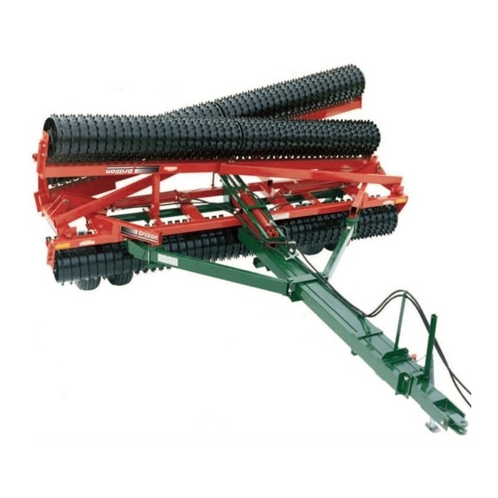
- Page 1 ® X-Fold Pulverizer Models: XXL184 and XXLO184 Widths: 38’, 40’, 42’, 44’, and 46’ Operator’s Manual LANDOLL CORPORATION 1900 North Street Marysville, Kansas 66508 (785) 562-5381 800-428-5655 ~ WWW.LANDOLL.COM 190rev0713 9J698...
- Page 2 190rev501 9J698...
-
Page 3: Table Of Contents
XXL184 PULVERIZER CONTENTS Introduction ---------------------------------------------------------------------------------------------------------- 3 Location Reference ---------------------------------------------------------------------------------------- 3 Parts Ordering ----------------------------------------------------------------------------------------------- 3 Safety Suggestions ----------------------------------------------------------------------------------------------- 4 Operating Instructions -------------------------------------------------------------------------------------------- 5 Designed Use ----------------------------------------------------------------------------------------------- 5 Bleeding Hydraulic Cylinders ---------------------------------------------------------------------------- 5 Hydraulic Lift ------------------------------------------------------------------------------------------------- 5 Field Operation ---------------------------------------------------------------------------------------------- 6 Hitch Adjustment (Used to Limit Soil Pushing) ------------------------------------------------------ 6 Transport Lock ---------------------------------------------------------------------------------------------- 7 Packer Wheel Adjustment -------------------------------------------------------------------------------- 7 Scraper Adjustment ---------------------------------------------------------------------------------------- 7... - Page 4 190rev501 9J698...
-
Page 5: Introduction
INTRODUCTION To obtain maximum benefits from the Brillion Pulverizer, please study this manual carefully before starting assembly or operation. A special section, “Assembly Instructions”, is included. This safety alert symbol is used to call your attention to instructions concerning personal safety. Federal law requires you to explain the safety and operating instructions furnished with this machine to each employee before they are allowed to operate the machine. -
Page 6: Safety Suggestions
SAFETY SUGGESTIONS Federal law requires you to explain the safety and operating instructions furnished with this machine to all employees before they are allowed to operate the machine. These must be repeated to the employees at the beginning of each season. Be sure to observe and follow the instructions for the safety of anyone operating or near the machine. - Page 7 Safety Signs & Decals There are three levels of hazard intensity that appear with the safety alert symbol on safety decals: DANGER, WARNING, and CAUTION. The level of hazard intensity is determined by the following definitions: DANGER - Immediate hazards which WILL result in severe personal injury or death. WARNING - Hazards or unsafe practices which COULD result in severe personal injury or death.
- Page 8 190rev501 Page 4B 9J698...
-
Page 9: Operating Instructions
OPERATING INSTRUCTIONS Designed Use The folding pulverizer is designed to pull behind wide model field cultivators and discs. It can be used as an indi- vidual unit with the tractor to prepare a seedbed or after seeding to break down and pulverize large surface clods. The long drawbar allows for easy, short turns when pulled behind other equipment. - Page 10 190rev501 9J698 Page 6...
-
Page 11: Transport Lock
Transport Lock Fold the wings for transport as described above. In transport relieve the hydraulic pressure until the cylinder transport lock is tight against pin in the lift arm. There should be no need to do anything with the pulverizer when going from field to transport or transport to field. - Page 12 190rev501 Page 8 9J698...
- Page 13 190rev501 9J698 Page 9...
- Page 14 Page 10 190rev501 9J698...
- Page 15 190rev501 9J698 Page 10A...
- Page 16 Page 11 190rev501 9J698...
- Page 17 Page 12 190rev501 9J698...
- Page 18 TELESCOPING DRAWBAR PIN, 1” X 9 1/4” KLIK PIN RETRACTED POSITION Hold the telescoping drawbar in the retracted position by extending the 1” x 9 1/4” pin horizontally through the end plates of the outer drawbar section and through the tube on the inner section between them.
- Page 19 190rev501 Page 13 9J698...
- Page 20 190rev501 9J698 Page 14...
- Page 21 190rev501 9J698 Page 15...
-
Page 22: Hydraulics
HYDRAULICS XXL-184 01/21/2013 and After 190rev0713 Page 15A 9J698... - Page 23 190rev501 Page16 9J698...
- Page 24 190rev1103 190rev501 9J698 Page16A...
- Page 25 190rev501 Page 17 9J698...
- Page 26 190rev501 9J698 Page18...
- Page 27 190rev501 Page 19 9J698...
- Page 28 Page 20 190rev501 9J698...
- Page 29 190rev501 Page 21 9J698...
-
Page 30: Led Warning Lights
LED Warning Lights Red LED Lamp Amber LED Lamp Amber LED Lamp LED Warning Lights Harness Flasher Control Module 7Pin/4Pin WP Harness When plugging in the LED 7-pin connector: 1) Make sure the tractor has a good clean receptacle, free of dirt and corrosion. 2) Make sure the 7-pin connector is inserted ALL the way in. - Page 31 Warning Light Placement Dimensions Light Module Location 70" Bracket Bracket 35" Rear Rear Bracket Bracket 15 1/2" 15 1/2" The Light Module is mounted on top of the Module Bracket Weldment and secured with two 1/4-20 X 1-1/2 screws and nuts. Screw, 1/4-20 X 1-1/2 Light Module...
- Page 32 LED Wiring Layout and Componenets Screw,1/4-20 X 1-1/2 LED Wiring Harness 7 Pin Harness Tie Strap Light Locknut, Module 1/4-20 7 Pin Harness Tie Strap Locknut, 5/8-11 Screw,1/4-20 X 1-1/2 Screw, 1/4-20 X 1-1/2 Locknut, Tie Strap 1/4-20 Strap Amber Locknut, 1/4-20 Warning...
- Page 33 LED Lamp and Harness Installation 1. Install each Tail Light Mount on the rear frame tube, approximately 35” from the center of the frame. Secure mounts with 5/8-11 U-Bolts and Locknuts. See page 21B. 2. Install the Light Module on top of the Module Bracket Weldment using two 1/4-20 X 1-1/2 Screws and Locknuts.
- Page 34 190rev501 Page 22 9J698...
-
Page 35: Hitch Lock Kit (Optional)
Hitch Lock Kit - Optional Do Not Remove Hitch to Install Spade Hitches: Remove the Safety Chain and set aside. Insert the Hitch Lock Up Channel into the Drawbar and line up bolt holes. Insert 2-3/4” bolt into the righthand hole, thread Lock Nut on. Do Not fully tighten at this time. Insert 4-1/2”... - Page 36 Hitch Lock Kit - Optional Do Not Remove Hitch to Install Clevis Hitches: Remove the Safety Chain and set aside. Insert the Hitch Lock Up Channel into the Drawbar and line up bolt holes. Insert 2-3/4” bolt into the righthand hole, thread Lock Nut on. Do Not fully tighten at this time. Insert 4-1/2”...
- Page 37 190rev501 9J698 Page 23...
-
Page 38: Specifications
Machine Specifications Frame .................Center - two 4" x 4" x 5/16" Wall Tubing Wings 5" x 5" x 3/16" Wall Tubing Drawbar - two 3" x 6" x 3/126" Wall Tubing 6" x 6" x 3/16" Wall Tubing Braces 3" x 6" x 3/16" Wall Tubing Hitch Weight - Transport with drawbar telescoped .............. - Page 39 Table provided for general use. NOTES:...
- Page 40 Equipment from Landoll Corporation is built to exacting standards ensured by ISO 9001 registration at all Landoll manufacturing facilities. X-Fold Pulverizer Models: XXL184, XXLO184 Widths: 38’, 40’, 42’, 44’, and 46’ Operator's Manual Re-Order Part Number 9J698 LANDOLL CORPORATION 1900 North Street...