Table of Contents
Advertisement
Quick Links
Advertisement
Table of Contents

Related Manuals for thomann Stairville DMX Invader 1024 NET


Summary of Contents for thomann Stairville DMX Invader 1024 NET
- Page 1 DMX Invader 1024 NET DMX controller user manual...
- Page 2 Musikhaus Thomann Thomann GmbH Hans-Thomann-Straße 1 96138 Burgebrach Germany Telephone: +49 (0) 9546 9223-0 E-mail: info@thomann.de Internet: www.thomann.de 10.01.2020, ID: 463871...
-
Page 3: Table Of Contents
Table of contents Table of contents General information..........................5 1.1 Further information........................... 6 1.2 Notational conventions........................7 1.3 Symbols and signal words....................... 9 Safety instructions..........................11 Features............................... 16 Installation..............................17 Connections and operating elements................... 20 Operating..............................33 6.1 Changing basic settings........................ 33 6.2 Assigning external devices...................... - Page 4 Table of contents 6.7 Working with shapes........................58 6.8 Installing firmware update......................61 Technical specifications........................62 Plug and connection assignment....................64 Protecting the environment......................66 DMX controller...
-
Page 5: General Information
Our products and user manuals are subject to a process of continuous development. We there‐ fore reserve the right to make changes without notice. Please refer to the latest version of the user manual which is ready for download under www.thomann.de. DMX Invader 1024 NET... -
Page 6: Further Information
General information 1.1 Further information On our website (www.thomann.de) you will find lots of further information and details on the following points: Download This manual is also available as PDF file for you to download. Use the search function in the electronic version to find the topics of Keyword search interest for you quickly. -
Page 7: Notational Conventions
General information 1.2 Notational conventions This manual uses the following notational conventions: Letterings The letterings for connectors and controls are marked by square brackets and italics. Examples: [VOLUME] control, [Mono] button. Displays Texts and values displayed on the device are marked by quotation marks and italics. Examples: ‘24ch’... - Page 8 General information Instructions The individual steps of an instruction are numbered consecutively. The result of a step is indented and highlighted by an arrow. Example: Switch on the device. Press [Auto]. ð Automatic operation is started. Switch off the device. Cross-references References to other locations in this manual are identified by an arrow and the specified page number.
-
Page 9: Symbols And Signal Words
General information 1.3 Symbols and signal words In this section you will find an overview of the meaning of symbols and signal words that are used in this manual. Signal word Meaning DANGER! This combination of symbol and signal word indicates an immediate dangerous situation that will result in death or serious injury if it is not avoided. - Page 10 General information Warning signs Type of danger Warning – danger zone. DMX controller...
-
Page 11: Safety Instructions
Safety instructions Safety instructions Intended use This device is intended to be used to control spot lights, dimmers, light effects, moving heads or other DMX-controlled devices. Use the device only as described in this user manual. Any other use or use under other operating conditions is considered to be improper and may result in personal injury or property damage. - Page 12 Safety instructions Safety DANGER! Danger for children Ensure that plastic bags, packaging, etc. are disposed of properly and are not within reach of babies and young children. Choking hazard! Ensure that children do not detach any small parts (e.g. knobs or the like) from the unit.
- Page 13 Safety instructions DANGER! Electric shock caused by short-circuit Always use proper ready-made insulated mains cabling (power cord) with a pro‐ tective contact plug. Do not modify the mains cable or the plug. Failure to do so could result in electric shock/death or fire. If in doubt, seek advice from a regis‐ tered electrician.
- Page 14 Safety instructions NOTICE! Operating conditions This device has been designed for indoor use only. To prevent damage, never expose the device to any liquid or moisture. Avoid direct sunlight, heavy dirt, and strong vibrations. Only operate the device within the ambient conditions specified in the chapter ‘Technical specifications’...
- Page 15 Safety instructions NOTICE! Power supply Before connecting the device, ensure that the input voltage (AC outlet) matches the voltage rating of the device and that the AC outlet is protected by a residual current circuit breaker. Failure to do so could result in damage to the device and possibly injure the user.
-
Page 16: Features
Features Features This DMX controller is specially suited for professional lighting requirements, such as at events, on rock stages, for dance bands, as well as for mobile DJ applications. Special features of the device: 2 × three-pin DMX outputs 1024 DMX channels in total 62 DMX-capable lamps / moving heads with up to 36 channels each 62 programmable Chases (100 scenes per Chase) 62 programmable scenes... -
Page 17: Installation
Installation Installation Unpack and check carefully there is no transportation damage before using the unit. Keep the equipment packaging. To fully protect the product against vibration, dust and moisture during transportation or storage use the original packaging or your own packaging material suitable for transport or storage, respectively. - Page 18 Installation Connections in DMX mode Connect the DMX output of the device (C) to the DMX input of the first DMX device (1). Con‐ nect the output of the first DMX device to the input of the second one, and so on to form a daisy chain.
- Page 19 Installation DMX outputs Two three-pin XLR sockets serve as DMX outputs. The following figure and the table show the pin assignment of the sockets. Ground DMX data (–) DMX data (+) DMX address and control chan‐ For each function of a DMX device (e.g., colour, brightness, flash interval, etc.), a dedicated nels control channel is provided.
-
Page 20: Connections And Operating Elements
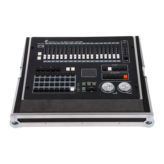
Connections and operating elements Connections and operating elements Front panel DMX controller... - Page 21 Connections and operating elements A Fader B, C Function buttons DMX Invader 1024 NET...
- Page 22 Connections and operating elements 1 USB-PORT USB port for data backup and import of stored data. 2 Fader These faders set the DMX values for each channel 1 … 36. 3 TIME Use this fader to change the duration of chase steps. 4 [1-18] Buttons for selecting faders for channels 1 …...
- Page 23 Connections and operating elements DMX Invader 1024 NET...
- Page 24 Connections and operating elements 6 [CHASE] Buttons for subsequently selecting a programmed Chase (sequence of several scenes). To select group A (programmed chaser A1 … A31), press [ A]. When the button is activated, the LED lights up. To select group B (programmed chaser B1 … B31), press [ B]. When the button is activated, the LED lights up. 7 [SCENE] Buttons for subsequently selecting a programmed scene.
- Page 25 Connections and operating elements 9 [FIXTURE] To select group A (A1 … A31), press [ A]. When the button is activated, the LED lights up. To select group B (B1 … B31), press [B]. When the button is activated, the LED lights up. If you press [FIXTURE] and then address the devices with the number buttons [1] …...
- Page 26 Connections and operating elements DMX controller...
- Page 27 Connections and operating elements 12 Display Indicates the current device activity or programme status. 13 [STOP] Button to exit the Shape Generator. When the button is activated, the LED lights up. 14 [PLAY] Button for subsequent selecting and editing a movement via [ Speed/Size]. When the button is activated, the LED flashes. 15 [Speed/Size] Button for selecting and editing the speed of movement and size.
- Page 28 Connections and operating elements 19 [COPY] Button for copying a step within chase editing. When the button is activated, the LED lights up. 20 [PASTE] Button for pasting copied steps within chase editing. When the button is activated, the LED lights up. 21 [INSERT] Button for inserting a new step within chase editing.
- Page 29 Connections and operating elements 25 [SWING / STEP] Button for changing the direction of chases. In Swing mode: Button for changing the rhythm of chases. If you press the button at a certain rhythm, the chase will be performed at the same rhythm. 26 [MODE / DELETE] Button for selecting the trigger mode.
- Page 30 Connections and operating elements 28 [PROGRAM] Button for setting the Programme mode. Press [PROGRAM] to go from work mode to edit mode and back to work mode. 29 [BLACKOUT] Button to activate the blackout Rear panel DMX controller...
- Page 31 Connections and operating elements 30 [ON / OFF] Switch to turn the device on or off. 31 [POWER IN] Connect the IEC chassis connector with fuse holder via the supplied power cord to an AC outlet that provides the voltage specified in the Technical Data. 32 [ACT / LINK] ACT: LED lights on network activity LINK: LED lights up on Ethernet connection to a signal source...
- Page 32 Connections and operating elements 37 [MIDI OUT] The device sends MIDI data via the "MIDI OUT" socket. 38 [MIDI THR] The "MIDI THRU" socket will forward the incoming MIDI data to the next MIDI device. 39 [AUDIO IN ] You can connect audio line signals (0,1 V ~ 1 V ) to this RCA socket to be used for the sound-controlled mode.
-
Page 33: Operating
Operating Operating 6.1 Changing basic settings Calling up the menu Press and hold [SETUP] for at least 2 seconds to enter the main menu. Turn the jog wheel [ Y/CROSS] to the left or right to select the desired submenu. When the desired submenu is highlighted, press the jog wheel [ Y/CROSS]. - Page 34 Operating Turn the jog wheel [ Y/CROSS] to the left or right to set the desired value and press the jog wheel [ Y/CROSS] to confirm. ð The setting is accepted. To return to the next higher menu level without changes, press [SETUP]. The following settings can be made in the main menu: Display Function...
- Page 35 Operating Display Function Set Net Protocol Selects the DMX protocol. The device supports the Art-Net protocol and the sACN protocol. Set Universe Defines a DMX universe. In the Art-Net and sACN protocols, the user must define a universe for two DMX universes. Set Colors Sets the foreground and background colour for the dis‐...
- Page 36 Operating Display Function Save File Saves the current file in the device to a USB stick. Set Default Resets the device to factory defaults. Version Displays the current firmware version. DMX controller...
- Page 37 Operating Setting the MIDI channel If you want the device to receive information via the MIDI interface, you can select the desired transmission channel. Command MIDI Note- Note Entry number Fader Value 0×90 00×00–0×12 Fader number Fader Page 0×90 0×13 Page number Chase Page 0×90...
- Page 38 Operating Command MIDI Note- Note Entry number Mode 0×90 0×1A Auto: The speed of the chase is controlled by the timing of the scenes and the Time fader. Swing: The speed of the Chase is con‐ trolled by the Swing button. Music: The speed of the chase is con‐...
- Page 39 Operating Command MIDI Note- Note Entry number Shape Size 0×90 0×21 Size value Shape Offset 0×90 0×22 Offset value Shape Dir 0×90 0×23 clockwise (0) counter-clockwise (1) Shape View 0×90 0×24 Pan Fine 0×90 0×25 Fine adjustment Pan disabled (0) Fine adjustment Pan enabled (1) Tilt Fine 0×90...
-
Page 40: Assigning External Devices
Operating 6.2 Assigning external devices Fixed assignment of DMX When assigning the fixed DMX addresses, make sure that the number of channels and the con‐ addresses trol parameters match the configuration of the connected external devices. The device is set for 62 external devices with 36 channels for each external device. The channel value of the external devices is controlled by the channel faders [1 …... - Page 41 Operating DMX address list for the num‐ bers of external devices The following table shows you which DMX address is assigned to the 36 channel faders by pressing the number buttons [1] … [31] . Important: The LEDs [ A] or [ B] of the [ FIXTURE] button must light up at that! Number buttons DMX address...
- Page 42 Operating Number buttons DMX address Number buttons DMX address A095 A351 A111 A367 A383 A143 A399 A159 A415 A175 A431 A191 A447 A207 DMX controller...
- Page 43 Operating Number buttons DMX address Number buttons DMX address A453 B180 A469 B196 A485 B212 B001 B228 B017 B244 B033 B260 B049 B276 B065 B292 B081 B308 B097 B324 B113 B340 B129 B356 B145 B372 DMX Invader 1024 NET...
- Page 44 Operating Number buttons DMX address Number buttons DMX address B161 B388 B177 B404 B178 DMX controller...
- Page 45 Operating Assignment of Pan and Tilt You can dynamically assign a DMX channel to each connected external device. A maximum of channels 62 external devices, each with up to 36 channels, can be selected. The channel value of the connected external devices is controlled by the channel faders [1 … 18] . Press [PROGRAM] to call up the programming mode.
- Page 46 Operating You can make the following settings when dynamically assigning DMX addresses: If the device to be assigned does not have a fine adjustment channel for Pan and Tilt, ‘**’ should be set as the value. Name Meaning Value 1. Channel Num Total number of device channels ** …...
- Page 47 Operating Name Meaning Value 6. YL Offset Channel Tilt movement, fine adjustment ** … 36 channel (8 bit) 7. Y Dir Tilt movement, direction <, > External devices with 16-bit resolution are controlled by two data channels per axis. External devices with 8-bit resolution are only controlled by one data channel per axis. DMX Invader 1024 NET...
- Page 48 Operating Manual control of devices Press [FIXTURE (A)] or [FIXTURE (B)] to select the assignment area A or B. ð The [FIXTURE] LED lights up. Press the number buttons [1 … 31] to select one or more external devices. If multiple external devices are selected at the same time, they must be of the same type.
- Page 49 Operating If the X / Y channel is controlled by the jog wheels, the channel faders are locked auto‐ matically. The X / Y position of the units can only be changed with the jog wheels. DMX Invader 1024 NET...
-
Page 50: Editing Scenes
Operating 6.3 Editing scenes A scene is a combination of the set channel values of the external devices. The device can store 62 scenes, which can be executed arbitrarily. In order to be able to execute several scenes and several chases simultaneously, the different values of the same control channel are calculated according to the HTP tech‐... - Page 51 Operating Example: You want to save the device's current setting as scene A10: Press [PROGRAM]. Press [SCENE (A)]. Press the number button [10]. Copying an existing scene Use [SCENE (A)] or [SCENE (B)] and the number buttons [1 … 31] to call up the scene you what to copy.
-
Page 52: Editing A Chase
Operating 6.4 Editing a Chase The device can store 62 chaser programmes, each with up to 100 steps. Steps correspond to scenes. Inserting steps in or removing Press [PROGRAM] to enter the Edit mode. from a chase ð The [PROGRAM] LED flashes. Press [CHASE (A)] or [CHASE (B)] and the number buttons [1 …... - Page 53 Operating Editing a step in a chase Press [STEP +] or [STEP -] to select the step in a chase you want to edit. Press and hold [TIME] while turning the jog wheel [X/SPEED] to set the running speed of the current step.
-
Page 54: Macros
Operating 6.5 Macros The individual combinations of manual settings, scenes, chasers and shapes can be stored together in macros. The device can record 31 macros that are accessed via the buttons. Recording a macro Press [PROGRAM] to enter the Edit mode. ð... -
Page 55: Enabling Programme Run
Operating 6.6 Enabling programme run Playing scenes Scenes can be played individually or as a sequence of multiple scenes. To start a sequence of multiple scenes, all scenes must be in the same group (A) or (B). Press [SCENE (A)] or [SCENE (B)]. Press [TYPE] until either the [Latch] LED or the [Swop] LED lights up. - Page 56 Operating Select the desired chase or chases using the number buttons [1 … 31]. ð The desired chase or chases are being played. If the number of chases to be played at the same time exceeds the permissible number, the message ‘Chase over load!’ appears in the display. If several chases are played simultaneously, the display shows the settings of the last chase in the sequence.
- Page 57 Operating Setting up triggers for chasers There are three types of triggers for chasers: Auto: The speed of the chase is controlled by the timing of the scenes and the Time fader. Swing: The speed of the Chase is controlled by the Swing button. Music: The speed of the chase is controlled by the rhythm of the music.
-
Page 58: Working With Shapes
Operating 6.7 Working with shapes Shapes are graphic movements (circle, line, square, etc.) that create dynamic effects. With the Shape Generator, different shapes can be created in different sizes, which run at different speeds. Each shape generator can drive various external devices. Up to 80 different shape effects can be generated: 20 ×... - Page 59 Operating Editing shapes The Shape Generator can be used in manual mode, in scenes and chases. Use [FIXTURE (A)] or [FIXTURE (B)] and the number buttons [1 … 31] to call up the desired external devices. Set the centre of the shape for the desired external devices using the X and Y coordi‐ nates.
- Page 60 Operating Turn the jog wheel [Y/CROSS] to the left or right to change the direction of the current shape. Press [STOP] to exit editing the Shape Generator. When the console is restarted, the set values are reset to the standard values. Playing shapes Press [PLAY].
-
Page 61: Installing Firmware Update
Operating Displaying shapes Press [VIEW]. ð The display shows the number of shape generators used in the current scene. 6.8 Installing firmware update Copy the file with the firmware update from the "DMX_MASTER" folder to a USB stick. Turn off the device. Insert the USB stick with the firmware update file into the USB port of the device. -
Page 62: Technical Specifications
Technical specifications Technical specifications Control protocols DMX512 Number of DMX channels 1024 Input connections MIDI 3 × DIN socket, 5-pin Audio signal RCA socket, 100 mV, 1 Vpp Voltage supply IEC chassis plug C14 Network RJ45 socket Output connections DMX control 2 ×... - Page 63 Technical specifications Weight 5.8 kg Ambient conditions Temperature range 0 °C…40 °C Relative humidity 50 %, non-condensing Further information Preset function External storage option DMX universes Max. control channels 1024 Ethernet DMX Invader 1024 NET...
-
Page 64: Plug And Connection Assignment
Plug and connection assignment Plug and connection assignment Introduction This chapter will help you select the right cables and plugs to connect your valuable equip‐ ment so that a perfect light experience is guaranteed. Please take our tips, because especially in ‘Sound & Light’ caution is indicated: Even if a plug fits into a socket, the result of an incorrect connection may be a destroyed DMX controller, a short circuit or ‘just’... - Page 65 Plug and connection assignment RCA connection Drawing and table indicate the pin assignment of an RCA plug. Signal Ground, shielding DMX Invader 1024 NET...
-
Page 66: Protecting The Environment
Protecting the environment Protecting the environment Disposal of the packaging mate‐ rial For the transport and protective packaging, environmentally friendly materials have been chosen that can be supplied to normal recycling. Ensure that plastic bags, packaging, etc. are properly disposed of. Do not just dispose of these materials with your normal household waste, but make sure that they are collected for recycling. - Page 68 Musikhaus Thomann · Hans-Thomann-Straße 1 · 96138 Burgebrach · Germany · www.thomann.de...
Need help?
Do you have a question about the Stairville DMX Invader 1024 NET and is the answer not in the manual?
Questions and answers