Table of Contents
Advertisement
Quick Links
Advertisement
Table of Contents

Related Manuals for thomann BOTEX Dr. RDM I DMX RDM Tester


Summary of Contents for thomann BOTEX Dr. RDM I DMX RDM Tester
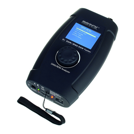
- Page 1 Dr. RDM I DMX RDM Tester Controller...
- Page 2 Thomann GmbH Hans-Thomann-Straße 1 96138 Burgebrach Germany Telephone: +49 (0) 9546 9223-0 Internet: www.thomann.de 05.03.2024, ID: 421279 (V3)
-
Page 3: Table Of Contents
Table of contents Table of contents General information..........................5 1.1 Symbols and signal words....................... 5 Safety instructions............................ 7 Features................................9 Installation and starting up........................ 10 Connections and controls........................13 Operating..............................15 6.1 Main menu............................16 6.2 DMX 512 test............................18 6.3 ... - Page 4 Dr. RDM I DMX RDM Tester Controller...
-
Page 5: General Information
Our products and documentation are subject to a process of continuous development. They are therefore subject to change. Please refer to the latest version of the documentation, which is ready for download under www.thomann.de. 1.1 Symbols and signal words In this section you will find an overview of the meaning of symbols and signal words that are used in this document. - Page 6 General information Warning signs Type of danger Warning – danger zone. Dr. RDM I DMX RDM Tester Controller...
-
Page 7: Safety Instructions
Safety instructions 2 Safety instructions Intended use This device is for testing devices that are controlled via DMX, RDM or MIDI or output these signals. Use the device only as described in this user manual. Any other use or use under other operating conditions is considered to be improper and may result in personal injury or property damage. - Page 8 Safety instructions NOTICE! Damage to the external power supply due to high voltages! The device is powered by an external power supply. The external power supply can be damaged if it is operated with the incorrect voltage or if high voltage peaks occur. In the worst case, excess voltages can also cause a risk of injury and fires. Make sure that the voltage specification on the external power supply matches the local power grid before plugging in the power supply.
-
Page 9: Features
Features 3 Features Universal test device for DMX, RDM and MIDI networks 5-pin DMX in and output MIDI input Plug-in power supply and adapter for 3-pin DMX plug included Operating via buttons and display on the unit Dr. RDM I DMX RDM Tester Controller... -
Page 10: Installation And Starting Up
Installation and starting up 4 Installation and starting up Unpack and check carefully there is no transportation damage before using the unit. Keep the equipment packaging. To fully protect the product against vibration, dust and moisture during transportation or storage use the original packaging or your own packaging material suitable for transport or storage, respectively. - Page 11 Installation and starting up NOTICE! Possible damage due to leaking batteries! Batteries can leak and cause permanent damage to the device. Take the batteries out of the device if it is not going to be used for an extended period of time.
- Page 12 Installation and starting up Charging the batteries Use the included power adapter to charge the inserted batteries. Connect the supplied power adapter to the power supply input of the device and then plug the power adapter into a mains socket. ð...
-
Page 13: Connections And Controls
Connections and controls 5 Connections and controls & D r R D M I M X R D M T e s t e r ö Normal Program Update DC INPUT: Under Voltage 9V 5 00mA Power Switch micro SD Dr. - Page 14 Connections and controls 1 Jog wheel for control and menu selection 2 Display. The display is turned off after an adjustable period of time without keystroke. Press the jog wheel to reactivate the display. 3 [DMX/RDM OUT] | 5-pin DMX/RDM output 4 [DMX/RDM IN] | 5-pin DMX/RDM input 5 [MIDI In] | MIDI input 6 [Power Switch] | Main switch.
-
Page 15: Operating
Operating 6 Operating The device can be powered by batteries or with the included power supply. Battery operation: Insert the batteries in the device. Ä ‘Inserting batteries’ on page 10 Operation with the power supply: Connect the supplied power adapter to the power supply input of the device and then plug the power adapter into a mains socket. -
Page 16: Main Menu
Operating 6.1 Main menu Selection in main menu Turn the jog wheel to highlight a menu item. Press the jog wheel to select the highlighted menu item. Press the jog wheel again to open the associated submenu. The display shows the available elements of the submenu. Select the ‘EXIT’... - Page 17 Operating Dr. RDM I DMX RDM Tester Controller...
-
Page 18: Dmx 512 Test
Operating 6.2 DMX 512 test This menu allows you to monitor the data packets being received by DMX-controlled devices or sending test data to the devices. Select the item ‘DMX-512 TEST’ from the main menu. Press the jog wheel to open the respective submenu. ð... - Page 19 Operating DMX packet test In the ‘DMX-512 Test’ submenu, select the item ‘DMX Packet Test’ . Press the jog wheel to open the respective submenu. ð If the wiring is correct and a DMX signal is received, the display shows the following values: If no signal is received, the display shows: Dr.
- Page 20 Operating In this case, check the wiring and the correct fit of the connectors. To return to the parent menu, select ‘EXIT’ and press the jog wheel to confirm. Dr. RDM I DMX RDM Tester Controller...
- Page 21 Operating Analysis of received DMX data In the ‘DMX-512 Test’ submenu, select the item ‘DMX Data Receive’ . Press the jog wheel to open the respective submenu. ð The display shows: It will display the received DMX value ( ‘000’ … ‘255’ ) for every 25 channels. To change the first displayed channel, use the jog wheel to select ‘Start’...
- Page 22 Operating ‘BAR’ : Bars of squares ‘RGB’ : Squares with RGB colour mixing ‘BRG’ : Squares with BGR colour mixing ‘HEX’ : Hexadecimal values Press the jog wheel. To return to the parent menu, select ‘EXIT’ and press the jog wheel to confirm. Dr.
- Page 23 Operating Analysis of transmitted DMX data In the ‘DMX-512 TEST’ submenu, select the item ‘DMX Data Send’ . Press the jog wheel to open the respective submenu. ð The display shows: In the ‘DMX-512 SEND’ submenu, select the item ‘Single Channel Mode’ . Press the jog wheel to open the respective submenu.
- Page 24 Operating To select the channel on which the data should be sent, select the item ‘Channel’ . Press the jog wheel. Use the jog wheel to set a value between 1 and 512 – or ‘All’ for transmission on all channels. To select an operating mode, select ‘Mode’...
- Page 25 Operating To set the rate of change, select ‘Speed’ . Press the jog wheel. Use the jog wheel to set a value between ‘level 0’ and ‘level 10’ . To return to the parent menu, select ‘EXIT’ and press the jog wheel to confirm. In the ‘DMX-512 SEND’...
- Page 26 Operating To change the display format, use the jog wheel to select ‘Format’ and press the jog wheel. Turn the jog wheel to select one of the following formats. ‘DEC’ : Decimal values ‘PER’ : Percentage values ‘BAR’ : Bars of squares ‘HEX’...
- Page 27 Operating Use the jog wheel to select the setting to be changed and press the jog wheel. Turn the jog wheel to select or adjust a value. The following table shows the menu items and choices. Menu item Choices Meaning ‘Pixel Type’...
- Page 28 Operating In the ‘DMX-512 SEND’ submenu, select the item ‘Chase Demo Mode’ . Press the jog wheel to open the respective submenu. ð The display shows: Use the jog wheel to select the setting to be changed and press the jog wheel. Turn the jog wheel to select or adjust a value.
- Page 29 Operating Menu item Choices Meaning ‘Total Pixel’ ‘1’ … ‘512’ Number of connected devices ‘Pixel Group’ Value within the range of Number of devices in a group ‘Total Pixel’ ‘Jump Pixel’ Value within the range of ‘Pixel Number of devices that will be switched within the group Group’...
-
Page 30: Rdm-Test
Operating 6.3 RDM-Test This menu allows you to retrieve information about the connected RDM-controlled devices or send test data to the devices. Select the ‘RDM DATA TEST’ item from the main menu. Press the jog wheel to open the respective submenu. ð... - Page 31 Operating Retrieve RDM parameters - Iden‐ tify Device In the ‘RDM DATA TEST’ submenu, select the item ‘Get&Set RDM Parameter’ . Press the jog wheel to open the respective submenu. ð The display shows: If the wiring is correct and an RDM-controlled device is found, the display shows real-time information about the device: Dr.
- Page 32 Operating If no signal is received, the display shows: In this case, check the wiring and the correct fit of the connectors. For more detailed information, use the jog wheel to select ‘Para’ . Press the jog wheel. Dr. RDM I DMX RDM Tester Controller...
- Page 33 Operating ð The display shows: The selectable parameters depend on the respective device, examples: ‘Identify Device’ , ‘Device Info’ , ‘DMX Start Address’ . To retrieve a parameter, select it with the jog wheel and press the jog wheel. Select ‘Get Parameter’...
- Page 34 Operating Use the jog wheel to select ‘Fresh’ to refresh the displayed information, or ‘EXIT’ to return to the parent menu. Press the jog wheel. Dr. RDM I DMX RDM Tester Controller...
- Page 35 Operating Retrieve RDM Device Informa‐ tion - Device Info In the ‘RDM DATA TEST’ submenu, select the item ‘Get&Set RDM Parameter’ . Press the jog wheel to open the respective submenu. ð The display shows: If the wiring is correct and an RDM-controlled device is found, the display shows real-time information about the device: Dr.
- Page 36 Operating If no signal is received, the display shows: In this case, check the wiring and the correct fit of the connectors. For more detailed information, use the jog wheel to select ‘Para’ . Press the jog wheel. Dr. RDM I DMX RDM Tester Controller...
- Page 37 Operating ð The display shows: The selectable parameters depend on the respective device, examples: ‘Identify Device’ , ‘Device Info’ , ‘DMX Start Address’ . To retrieve a parameter, select it with the jog wheel and press the jog wheel. Select ‘Get Parameter’...
- Page 38 Operating Use the jog wheel to select ‘More Info’ to access further parameters. Use the jog wheel to select ‘Fresh’ to refresh the displayed information, or ‘EXIT’ to return to the parent menu. Press the jog wheel. Dr. RDM I DMX RDM Tester Controller...
- Page 39 Operating Changing RDM parameters In the ‘RDM DATA TEST’ submenu, select the item ‘Get&Set RDM Parameter’ . Press the jog wheel to open the respective submenu. ð The display shows: If the wiring is correct and an RDM-controlled device is found, the display shows real-time information about the device: Dr.
- Page 40 Operating If no signal is received, the display shows: In this case, check the wiring and the correct fit of the connectors. To change individual parameters, use the jog wheel to select ‘Para’ . Press the jog wheel. Dr. RDM I DMX RDM Tester Controller...
- Page 41 Operating ð The display shows: The selectable parameters depend on the respective device, examples: ‘Identify Device’ , ‘Device Info’ , ‘DMX Start Address’ . To retrieve a parameter, select it with the jog wheel and press the jog wheel. Select ‘Set Parameter’...
- Page 42 Operating Use the jog wheel to select ‘Start Identify’ to start or ‘Stop Identify’ to stop the identifica‐ tion. Press the jog wheel. To select which devices should be affected by the change, use the jog wheel to select ‘Only self’...
- Page 43 Operating Display or change of the DMX address of an RDM-controlled device In the ‘RDM DATA TEST’ submenu, select the item ‘Get&Set RDM Parameter’ . Press the jog wheel to open the respective submenu. ð The display shows: Dr. RDM I DMX RDM Tester Controller...
- Page 44 Operating If the wiring is correct and an RDM-controlled device is found, the display shows real-time information about the device: If no signal is received, the display shows: Dr. RDM I DMX RDM Tester Controller...
- Page 45 Operating In this case, check the wiring and the correct fit of the connectors. To change individual parameters, use the jog wheel to select ‘Para’ . Press the jog wheel. ð The display shows: Use the jog wheel to select ‘Para: DMX Start Address’ and press the jog wheel. Dr.
- Page 46 Operating To display the current DMX address, select ‘Get Parameter’ and press the jog wheel. ð The display shows, for example: Use the jog wheel to select ‘Fresh’ to refresh the displayed information, or ‘EXIT’ to return to the parent menu. Press the jog wheel. Dr.
- Page 47 Operating To change the DMX address, use the jog wheel to select ‘Set Parameter’ and press the jog wheel. ð The display shows, for example: Use the jog wheel to select ‘Channel:’ and press the jog wheel. Set the desired value with the jog wheel. Press the jog wheel to confirm. Dr.
- Page 48 Operating To select which devices should be affected by the change, use the jog wheel to select ‘Only self’ and press the jog wheel. Turn the jog wheel to select one of the following formats. ‘Only Self’ : Change only affects the selected device ‘Same mfrs’...
- Page 49 Operating Software update of an RDM-con‐ trolled device In the ‘RDM DATA TEST’ submenu, select the item ‘Update RMD device’ . Press the jog wheel to open the respective submenu. ð The display shows: Dr. RDM I DMX RDM Tester Controller...
- Page 50 Operating If the wiring is correct and an RDM-controlled device is found, the display shows real-time information about the device: If no signal is received, the display shows: Dr. RDM I DMX RDM Tester Controller...
- Page 51 Operating In this case, check the wiring and the correct fit of the connectors. Insert a micro SD card with the required software into the micro SD slot of the device. Use the jog wheel to select ‘Send: Single device’ . Press the jog wheel. ð...
-
Page 52: Midi-Test
Operating 6.4 MIDI-Test This menu allows you to test the data of a MIDI-controlled device. Connect a MIDI device to the MIDI input. Select the item ‘MIDI Receive’ from the main menu. Dr. RDM I DMX RDM Tester Controller... - Page 53 Operating Press the jog wheel to open the respective submenu. ð The display shows: Dr. RDM I DMX RDM Tester Controller...
- Page 54 Operating After a few seconds, the ‘ACT’ indicator appears in the lower left corner of the display. Once the data have been received from a MIDI device, the display shows: To return to the parent menu, select ‘EXIT’ and press the jog wheel to confirm. Dr.
-
Page 55: Cable Test
Operating 6.5 Cable test This menu allows you to test a DMX cable. Connect the cable to be tested to the DMX input and the DMX output. Select the item ‘CABLE TEST’ from the main menu. Press the jog wheel to open the respective submenu. ð... -
Page 56: Device Settings
Operating Use the jog wheel to select ‘Test’ and press the jog wheel. ð After a few seconds, the display shows the test result. If all wires are correctly connected, the display shows: To repeat the test, select ‘Try Again’ and press the jog wheel to confirm. To return to the parent menu, select ‘EXIT’... - Page 57 Operating Select the ‘SYSTEM Setup’ item from the main menu. Press the jog wheel to open the respective submenu. ð The display shows: Dr. RDM I DMX RDM Tester Controller...
- Page 58 Operating Turn the jog wheel to scroll down the list: Dr. RDM I DMX RDM Tester Controller...
- Page 59 Operating Use the jog wheel to select the setting to be changed and press the jog wheel. Turn the jog wheel to select or adjust a value. The following table shows the menu items and choices. Menu item Choices Meaning ‘TX Start Code’...
- Page 60 Operating Menu item Choices Meaning ‘Auto Mask Device’ ‘ON’ A connected RDM-controlled device does not appear in the overview. If you set its DMX address, the other devices without DMX address appear in the overview. ‘OFF’ A connected RDM-controlled device appears in the overview. ‘DMX Output When RDM’...
-
Page 61: Technical Specifications
Technical specifications 7 Technical specifications Control protocols DMX512, RDM, MIDI Input connections DMX/RDM control 1 × XLR panel plug, 5-pin MIDI 1 × DIN socket, 5-pin Power supply 1 × Socket for connecting the power adapter Data interface 1 × Micro-SD card slot Output connections DMX/RDM control 1 ×... - Page 62 Technical specifications Weight 0.28 kg Ambient conditions Temperature range 0 °C…40 °C Relative humidity 20%…80% (non-condensing) Further information Accessory type DMX tester Dr. RDM I DMX RDM Tester Controller...
-
Page 63: Plug And Connection Assignment
Plug and connection assignment 8 Plug and connection assignment Introduction This chapter will help you select the right cables and plugs to connect your valuable equip‐ ment so that a perfect light experience is guaranteed. Please take our tips, because especially in ‘Sound & Light’ caution is indicated: Even if a plug fits into a socket, the result of an incorrect connection may be a destroyed DMX controller, a short circuit or ‘just’... -
Page 64: Protecting The Environment
Protecting the environment 9 Protecting the environment Disposal of the packing material Environmentally friendly materials have been chosen for the packaging. These materials can be sent for normal recycling. Ensure that plastic bags, packaging, etc. are disposed of in the proper manner. - Page 65 Repairing a device or passing it on to another user is an ecologically valuable alternative to disposal. You can return your old device to Thomann GmbH at no charge. Check the current conditions on www.thomann.de. If your old device contains personal data, delete those data before disposing of it.
- Page 66 Notes Dr. RDM I DMX RDM Tester Controller...
- Page 68 Musikhaus Thomann · Hans-Thomann-Straße 1 · 96138 Burgebrach · Germany · www.thomann.de...
Need help?
Do you have a question about the BOTEX Dr. RDM I DMX RDM Tester and is the answer not in the manual?
Questions and answers