Advertisement
Table of Contents
- 1 Table of Contents
- 2 General Information
- 3 Further Information
- 4 Notational Conventions
- 5 Symbols and Signal Words
- 6 Safety Instructions
- 7 Features
- 8 Installation and Starting up
- 9 Connections and Controls
- 10 Operating on a PC
- 11 Technical Specifications
- 12 Plug and Pin Assignments
- 13 Protecting the Environment
- Download this manual
Advertisement
Table of Contents

Related Manuals for thomann the t.racks DSP 4x4 Amp 4.250


Summary of Contents for thomann the t.racks DSP 4x4 Amp 4.250
- Page 1 DSP 4x4 Amp 4.250, DSP 4x4 Amp100V Controller...
- Page 2 Thomann GmbH Hans-Thomann-Straße 1 96138 Burgebrach Germany Telephone: +49 (0) 9546 9223-0 Internet: www.thomann.de 13.06.2023, ID: 555931, 555941...
-
Page 3: Table Of Contents
Table of contents Table of contents General information..........................4 1.1 Further information........................... 5 1.2 Notational conventions........................5 1.3 Symbols and signal words....................... 6 Safety instructions............................. 8 Features............................... 10 Installation and starting up........................ 12 Connections and controls........................13 Operating on a PC........................... 16 Technical specifications........................ -
Page 4: General Information
Our products and user manuals are subject to a process of continuous development. We there‐ fore reserve the right to make changes without notice. Please refer to the latest version of the user manual which is ready for download under www.thomann.de. DSP 4x4 Amp 4.250, DSP 4x4 Amp100V... -
Page 5: Further Information
General information 1.1 Further information On our website (www.thomann.de) you will find lots of further information and details on the following points: Download This manual is also available as PDF file for you to download. Use the search function in the electronic version to find the topics of Keyword search interest for you quickly. -
Page 6: Symbols And Signal Words
General information Letterings The letterings for connectors and controls are marked by square brackets and italics. Examples: [VOLUME] control, [Mono] button. Displays Texts and values displayed on the device are marked by quotation marks and italics. Examples: ‘24ch’ , ‘OFF’ . Instructions The individual steps of an instruction are numbered consecutively. - Page 7 General information Signal word Meaning DANGER! This combination of symbol and signal word indicates an immediate dangerous situation that will result in death or serious injury if it is not avoided. NOTICE! This combination of symbol and signal word indicates a pos‐ sible dangerous situation that can result in material and environmental damage if it is not avoided.
-
Page 8: Safety Instructions
Safety instructions Safety instructions Intended use This device is intended to be used for amplification, mixing and playback of signals from musical instruments and microphones. Use the device only as described in this user manual. Any other use or use under other operating conditions is considered to be improper and may result in personal injury or property damage. - Page 9 Safety instructions DANGER! Danger to life due to electric current! Within the device there are areas where high voltages may be present. Never remove any covers. There are no user-serviceable parts inside. Do not use the device when covers, safety equipment or optical components are missing or damaged. DANGER! Risk of death from electrical current! The output voltages of modern high-performance amplifiers may result in death or serious injury.
-
Page 10: Features
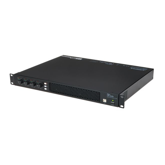
Features Features DSP 4x4 Amp 4.250 4-channel DSP installation power amplifier Front-side power switch 4 × 250 W into 8 ohms or 4 × 350 W into 4 ohms Programming via USB 3 front-side buttons for preset switching 3 rear-side contact inputs via screw terminals for preset switching Inputs: 4 ×... - Page 11 Features DSP 4x4 Amp100V 4-channel DSP installation power amplifier Front-side power switch 4 × 40 W into 8 ohms Programming via USB 3 front-side buttons for preset switching 3 rear-side contact inputs via screw terminals for preset switching Inputs: 4 × XLR (balanced) Outputs: 4 ×...
-
Page 12: Installation And Starting Up
Installation and starting up Installation and starting up Unpack and check carefully there is no transportation damage before using the unit. Keep the equipment packaging. To fully protect the product against vibration, dust and moisture during transportation or storage use the original packaging or your own packaging material suitable for transport or storage, respectively. -
Page 13: Connections And Controls
Connections and controls Connections and controls Front ö#$ & [CLIP] LED for each channel | The LED lights up when the signal on the respective input is overloading. [SIG] LEDs for each channel | The LED lights up when a signal is present at the respective input. Rotary control [CH 1]…[CH 4] | Controls the output level of the corresponding channel. - Page 14 Connections and controls Back DSP 4×4 Amp 4.250 Connection for the power cable Screw terminal strip for switching the presets. The relevant preset is called up through potential-free bridging of pins [Gnd] and [U01]…[U03] for 2 seconds. Switch to toggle the supply voltage [AMP OUT] | Outputs [CH1]…[CH4], designed as Speaker Twist [PRE OUT] | Outputs [1]…[4], designed as 6.35 mm (1/4-inch) jack sockets (mono, balanced) [INPUT] | Inputs [CH1]…[CH4], designed as XLR (mono, balanced)
- Page 15 Connections and controls DSP 4×4 Amp100V Connection for the power cable [MODE] | Screw terminal strip for switching the presets. The relevant preset is called up through potential-free bridging of pins [Gnd] and [U01]…[U03]. [AMP OUT] | 100 V outputs [CH 1]…[CH 4], designed as screw terminal strip [PRE OUT] | Outputs [1]…[4], designed as 6.35 mm (1/4-inch) jack sockets (mono, balanced) [INPUT] | Inputs [CH1]…[CH4], designed as XLR (mono, balanced) DSP 4x4 Amp 4.250, DSP 4x4 Amp100V...
-
Page 16: Operating On A Pc
Operating on a PC Operating on a PC Install and start the software. Insert the software CD into the disk drive of your Windows PC and start the installation programme that matches the device version. Follow the instructions of the installation programme to completion. Connect your PC to the device via a USB cable and turn on the device. - Page 17 Operating on a PC Components of the programme All tabs of the programme window have a similar structure and are divided into the following window areas: ö & Tab for selecting a function group Main menu Button for the status of the connection to the PC DSP 4x4 Amp 4.250, DSP 4x4 Amp100V Controller...
- Page 18 Operating on a PC Display area Control area Buttons for quick access to important presets Main menu Menu item Meaning ‘File’ Loading user presets and saving them on the PC ‘Link’ Assignment of input to output channels ‘Copy’ Copying parameter settings from one input or output channel to another ‘Lock’...
- Page 19 Operating on a PC Buttons for quick access to important presets Area Meaning ‘Address’ Display of the marking of the device ‘Preset’ Display of the current user's preset ‘Store’ Saving a user preset ‘Recall’ Recalling a user preset DSP 4x4 Amp 4.250, DSP 4x4 Amp100V Controller...
- Page 20 Operating on a PC “Gain” tab DSP 4x4 Amp 4.250, DSP 4x4 Amp100V Controller...
- Page 21 Operating on a PC Area Meaning Display area Indicates the waveform of the input and output channels. Use the radio buttons ‘Inx’ and ‘Outx’ to determine the inputs and outputs to be displayed. Control area Drag the faders with the mouse to adjust the levels for the input and output channels. The ‘Mute’ button mutes or unmutes the respective channel.
- Page 22 Operating on a PC “Gate” tab DSP 4x4 Amp 4.250, DSP 4x4 Amp100V Controller...
- Page 23 Operating on a PC Area Meaning Display area Shows the current settings of the noise gate for the respective channel, with a symbolic level indicator symbol appearing next to it for the input channels. The red dot represents the threshold level at which the noise gate opens.
- Page 24 Operating on a PC “Comp” tab DSP 4x4 Amp 4.250, DSP 4x4 Amp100V Controller...
- Page 25 Operating on a PC Area Meaning Display area Shows the current settings of the compressor function for the respective output channel, with a sym‐ bolic level indicator symbol appearing next to it for all output channels. The red dot marks the threshold from which the compressor operates.
- Page 26 Operating on a PC “Delay” tab DSP 4x4 Amp 4.250, DSP 4x4 Amp100V Controller...
- Page 27 Operating on a PC Area Meaning Display area Shows the set delays for all output channels. Control area Drag the faders with the mouse to adjust the delay for the respective channel. In the ‘Unit’ area, you can select the measuring unit milliseconds (ms), meters (m) or feet (ft). DSP 4x4 Amp 4.250, DSP 4x4 Amp100V Controller...
- Page 28 Operating on a PC “Matrix” tab DSP 4x4 Amp 4.250, DSP 4x4 Amp100V Controller...
- Page 29 Operating on a PC Area Meaning Display area Shows the current interconnection of input to output channels. Input and output channels can be renamed. Click on a function area (such as ‘PEQ’ or ‘DELAY’ ) to open the tab. Here you can enter the corresponding parameters directly. Control area With a mouse click you can interconnect each input with each output channel.
- Page 30 Operating on a PC Tabs “Out 1” – “‘Out 4” DSP 4x4 Amp 4.250, DSP 4x4 Amp100V Controller...
- Page 31 Operating on a PC Area Meaning Display area Use the radio buttons ‘Mag’ or ‘Phase’ to switch the diagram from Cartesian coordinates (level vs. fre‐ quency) to polar coordinates (angle vs. frequency). Use the radio button ‘SHOW ALL EQ’ to show the parameters for all seven of the frequency bands. The corner points of the equalizer can be moved in the display area with the mouse.
-
Page 32: Technical Specifications
Technical specifications Technical specifications DSP 4x4 Amp 4.250 Amp class Input connections Power supply IEC chassis plug C14 USB interface 1 × USB-B Audio signal Type 4 × XLR (mono, balanced) Level +12 dBu Impedance 20 kΩ (balanced), 10 kΩ (unbalanced) Output connections Audio signal Type... - Page 33 Technical specifications Frequency response 20 Hz…20 kHz –0.3 dB Signal-to-noise ratio > 105 dBu Total harmonic distortion (THD) < 0.03 % (1 kHz, –10 dBu, 4 Ω) Crosstalk > 70 dBu 20 Hz…20 kHz Digital signal processing Digital signal processor 32 bit A/D-D/A converter 24 bit...
- Page 34 Technical specifications Further information 2-way stereo 3-way stereo Digital Delay Limiter Computer remote Suitable for rack mounting Bridged operation Temperature-controlled fan Convection cooling DSP 4x4 Amp 100V Amp class Input connections Power supply IEC chassis plug C14 USB interface 1 × USB-B DSP 4x4 Amp 4.250, DSP 4x4 Amp100V Controller...
- Page 35 Technical specifications Audio signal Type 4 × XLR (mono, balanced) Level +12 dBu Impedance 20 kΩ (balanced), 10 kΩ (unbalanced) Output connections Audio signal Type Screw terminal strip 4 × 6.35 mm (1/4-inch) jack socket (mono, balanced, Pre Out) Level +43 dBu Impedance 100 Ω...
- Page 36 Technical specifications A/D-D/A converter 24 bit Sampling rate 48 kHz Supply voltage 230 V 50 Hz Dimensions (W × H × D) 482 mm × 44 mm × 339 mm | 1 RU Weight 8.1 kg Ambient conditions Temperature range 0 °C…40 °C Relative humidity 20 %…80 %, non-condensing...
- Page 37 Technical specifications Further information 2-way stereo 3-way stereo Digital Delay Limiter Computer remote Suitable for rack mounting Bridged operation Temperature-controlled fan Convection cooling DSP 4x4 Amp 4.250, DSP 4x4 Amp100V Controller...
-
Page 38: Plug And Pin Assignments
Plug and pin assignments Plug and pin assignments Introduction This chapter will help you select the right cables and plugs to connect your valuable equip‐ ment in such a way that a perfect sound experience is ensured. Please note these advices, because especially in ‘Sound & Light’ caution is indicated: Even if a plug fits into the socket, an incorrect connection may result in a destroyed power amp, a short circuit or ‘just’... - Page 39 Plug and pin assignments 1/4" TRS phone plug (mono, bal‐ anced) Signal (in phase, +) Signal (out of phase, –) Ground Speaker Twist chassis connector 1, + Signal 1 (in phase) 1, – Signal 1 (out of phase) 2, + Signal 2 (in phase) 2, –...
-
Page 40: Protecting The Environment
Protecting the environment Protecting the environment Disposal of the packaging mate‐ rial For the transport and protective packaging, environmentally friendly materials have been chosen that can be supplied to normal recycling. Ensure that plastic bags, packaging, etc. are properly disposed of. Do not just dispose of these materials with your normal household waste, but make sure that they are collected for recycling. - Page 41 Notes DSP 4x4 Amp 4.250, DSP 4x4 Amp100V Controller...
- Page 42 Notes DSP 4x4 Amp 4.250, DSP 4x4 Amp100V Controller...
- Page 44 Musikhaus Thomann · Hans-Thomann-Straße 1 · 96138 Burgebrach · Germany · www.thomann.de...
Need help?
Do you have a question about the the t.racks DSP 4x4 Amp 4.250 and is the answer not in the manual?
Questions and answers