Table of Contents
Advertisement
Advertisement
Table of Contents

Related Manuals for thomann t.racks DSP 4x4 Mini


Summary of Contents for thomann t.racks DSP 4x4 Mini
- Page 1 DSP 4x4 Mini Controller...
- Page 2 Thomann GmbH Hans-Thomann-Straße 1 96138 Burgebrach Germany Telephone: +49 (0) 9546 9223-0 Internet: www.thomann.de 04.12.2023, ID: 448459 (V3)
-
Page 3: Table Of Contents
Table of contents Table of contents General information..........................5 1.1 Symbols and signal words....................... 5 Safety instructions............................. 7 Features................................9 Installation and starting up........................ 10 Connections and controls........................11 Operating on the computer....................... 12 Technical specifications........................28 Plug and connection assignment....................31 Protecting the environment...................... - Page 4 DSP 4x4 Mini Controller...
-
Page 5: General Information
Our products and documentation are subject to a process of continuous development. They are therefore subject to change. Please refer to the latest version of the documentation, which is ready for download under www.thomann.de. 1.1 Symbols and signal words In this section you will find an overview of the meaning of symbols and signal words that are used in this document. - Page 6 General information Warning signs Type of danger Warning – high-voltage. Warning – danger zone. DSP 4x4 Mini Controller...
-
Page 7: Safety Instructions
Safety instructions Safety instructions Intended use This device is intended to be used for amplification, mixing and playback of signals from musical instruments and microphones. Use the device only as described in this user manual. Any other use or use under other operating conditions is considered to be improper and may result in personal injury or property damage. - Page 8 Safety instructions DANGER! Danger to life due to electric current! Within the device there are areas where high voltages may be present. Never remove any covers. There are no user-serviceable parts inside. Do not use the device when covers, safety equipment or optical components are missing or damaged. NOTICE! Damage to the device if operated in unsuitable ambient conditions! The device can be damaged if it is operated in unsuitable ambient conditions.
-
Page 9: Features
Features Features Ultra compact 4-Channel DSP Inputs: 4 × 1/4" phone socket (balanced) Outputs: 4 × 1/4" phone socket (balanced) USB connection for control via PC using the supplied software Comprehensive setting options for optimal sound – Parametric Equalizer – Graphic Equalizer –... -
Page 10: Installation And Starting Up
Installation and starting up Installation and starting up Unpack and check carefully there is no transportation damage before using the unit. Keep the equipment packaging. To fully protect the product against vibration, dust and moisture during transportation or storage use the original packaging or your own packaging material suitable for transport or storage, respectively. -
Page 11: Connections And Controls
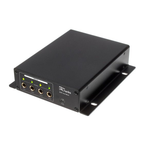
Connections and controls Connections and controls INPUT DSP 4x4 Mini OUTPUT SIGNAL CH 1 CH 2 CH 3 CH 4 CH 1 CH 2 CH 3 CH 4 ö % & Front LEDs [1], [2], [3], [4] | The LED lights up when a signal is present at the respective input. Inputs [CH 1] …... -
Page 12: Operating On The Computer
Operating on the computer Operating on the computer Install and start the software. Insert the software CD into the disk drive of your Windows PC and start the installation programme that matches the device version. Follow the instructions of the installation programme to completion. Connect your PC to the device via a USB cable and turn on the device. - Page 13 Operating on the computer Components of the programme All tabs of the programme window have a similar structure and are divided into the following window areas: ö & Tab for selecting a function group Main menu Button for the status of the connection to the PC DSP 4x4 Mini Controller...
- Page 14 Operating on the computer Display area Control area Buttons for quick access to important presets Main menu Menu item Meaning ‘File’ Loading user presets and saving them on the PC ‘Link’ Assignment of input to output channels ‘Copy’ Copying parameter settings from one input or output channel to another ‘Lock’...
- Page 15 Operating on the computer Buttons for quick access to important presets Range Meaning ‘Address’ Display of the marking of the device ‘Preset’ Display of the current user's preset ‘Store’ Saving user preset ‘Recall’ Recalling user preset DSP 4x4 Mini Controller...
- Page 16 Operating on the computer ‘Gain’ tab DSP 4x4 Mini Controller...
- Page 17 Operating on the computer Range Meaning Display area The waveform of input and output channels is graphically displayed. Use the radio buttons ‘Inx’ and ‘Outx’ to determine the inputs and outputs to be displayed. Control area Drag the faders with the mouse to adjust the levels for the input and output channels. The ‘Mute’ button mutes or unmutes the respective channel.
- Page 18 Operating on the computer ‘Gate’ tab DSP 4x4 Mini Controller...
- Page 19 Operating on the computer Range Meaning Display area Shows the current settings of the noise gate for the respective channel, with a symbolic level indicator symbol appearing next to it for the input channels. The red dot represents the threshold level at which the noise gate opens.
- Page 20 Operating on the computer ‘Comp’ tab DSP 4x4 Mini Controller...
- Page 21 Operating on the computer Range Meaning Display area Shows the current settings of the compressor function for the respective output channel, with a sym‐ bolic level indicator symbol appearing next to it for all output channels. The red dot marks the threshold from which the compressor operates.
- Page 22 Operating on the computer ‘Delay’ tab DSP 4x4 Mini Controller...
- Page 23 Operating on the computer Range Meaning Display area Shows the set delays for all output channels. Control area Drag the faders with the mouse to adjust the delay for the respective channel. In the Unit area, you can select the measuring unit milliseconds (ms), meters (m) or feet (ft). DSP 4x4 Mini Controller...
- Page 24 Operating on the computer ‘Matrix’ tab DSP 4x4 Mini Controller...
- Page 25 Operating on the computer Range Meaning Display area Shows the current interconnection of input to output channels. Input and output channels can be renamed. Click on a function area (such as ‘PEQ’ or ‘DELAY’ ) to open the tab. Here you can enter the corresponding parameters directly. Control area With a mouse click you can interconnect each input with each output channel.
- Page 26 Operating on the computer ‘Out 1’ – ‘Out 4’ DSP 4x4 Mini Controller...
- Page 27 Operating on the computer Range Meaning Display area Use the radio buttons ‘Mag’ or ‘Phase’ to switch the diagram from Cartesian coordinates (level vs. fre‐ quency) to polar coordinates (angle vs. frequency). Use the radio button ‘SHOW ALL EQ’ to show the parameters for all seven of the frequency bands. The corner points of the equalizer can be moved in the display area with the mouse.
-
Page 28: Technical Specifications
Technical specifications Technical specifications Input connections Power supply Socket for power adapter USB interface USB-B Audio signal Type 4 × 6.3-mm jack socket, balanced Level +12 dBu Impedance 20 kΩ (stereo), 10 kΩ (mono) Output connections Audio signal Type 4 × 6.3-mm jack socket, balanced Level +12 dBu... - Page 29 Technical specifications Digital signal processing Digital signal processor 32 bit A/D-D/A converter 24 bit Sampling rate 48 kHz Power supply External power adapter, 100 - 240 V 50/60 Hz Operating voltage 12 V / 1 A, centre positive Dimensions (W × H × D) 160 mm ×...
- Page 30 Technical specifications Further information 2-way stereo 3-way stereo Digital Delay Limiter Computer remote Suitable for rack mounting DSP 4x4 Mini Controller...
-
Page 31: Plug And Connection Assignment
Plug and connection assignment Plug and connection assignment Introduction This chapter will help you select the right cables and plugs to connect your valuable equip‐ ment in such a way that a perfect sound experience is ensured. Please note these advices, because especially in ‘Sound & Light’ caution is indicated: Even if a plug fits into the socket, an incorrect connection may result in a destroyed power amp, a short circuit or ‘just’... - Page 32 Plug and connection assignment 1/4" TS phone plug (mono, unbalanced) Signal Ground, shielding 1/4" TRS phone plug (mono, bal‐ anced) Signal (in phase, +) Signal (out of phase, –) Ground DSP 4x4 Mini Controller...
-
Page 33: Protecting The Environment
Protecting the environment Protecting the environment Disposal of the packaging mate‐ rial For the transport and protective packaging, environmentally friendly materials have been chosen that can be supplied to normal recycling. Ensure that plastic bags, packaging, etc. are properly disposed of. Do not just dispose of these materials with your normal household waste, but make sure that they are collected for recycling. - Page 34 Notes DSP 4x4 Mini Controller...
- Page 36 Musikhaus Thomann · Hans-Thomann-Straße 1 · 96138 Burgebrach · Germany · www.thomann.de...
Need help?
Do you have a question about the t.racks DSP 4x4 Mini and is the answer not in the manual?
Questions and answers