Table of Contents
Advertisement
Advertisement
Table of Contents

Subscribe to Our Youtube Channel
Related Manuals for thomann the t.racks DSP 204


Summary of Contents for thomann the t.racks DSP 204
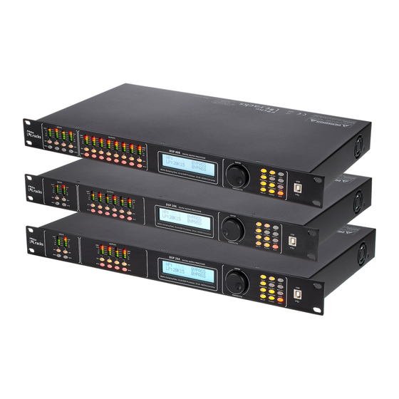
- Page 1 DSP 204, DSP 206, DSP 408 Controller...
- Page 2 Thomann GmbH Hans-Thomann-Straße 1 96138 Burgebrach Germany Telephone: +49 (0) 9546 9223-0 Internet: www.thomann.de 04.12.2023, ID: 435191, 435192, 435194 (V3)
-
Page 3: Table Of Contents
Table of contents Table of contents General information......................5 1.1 Symbols and signal words................... 5 Safety instructions......................... 6 Features............................7 Installation and starting up....................8 Connections and controls....................10 Operating on the unit......................12 Control on the computer....................17 Technical specifications....................27 Plug and connection assignment................. - Page 4 DSP 204, DSP 206, DSP 408 Controller...
-
Page 5: General Information
Our products and documentation are subject to a process of continuous develop‐ ment. They are therefore subject to change. Please refer to the latest version of the documentation, which is ready for download under www.thomann.de. 1.1 Symbols and signal words In this section you will find an overview of the meaning of symbols and signal words that are used in this document. -
Page 6: Safety Instructions
Safety instructions Safety instructions Intended use This device is intended to be used for amplification, mixing and playback of signals from musical instruments and microphones. Use the device only as described in this user manual. Any other use or use under other operating conditions is considered to be improper and may result in personal injury or property damage. -
Page 7: Features
Features Features Digital mixer Inputs: – DSP 204 (item no. 435191): 2 mono channels (XLR panel sockets) for signals with line level – DSP 206 (item no. 435192): 2 mono channels (XLR panel sockets) for signals with line level – DSP 408 (item no. -
Page 8: Installation And Starting Up
Installation and starting up Installation and starting up Unpack and check carefully there is no transportation damage before using the unit. Keep the equipment packaging. To fully protect the product against vibration, dust and moisture during transportation or storage use the original packaging or your own packaging material suitable for transport or storage, respectively. - Page 9 Installation and starting up Configuration example 2 The illustrations show schematically how one device or several devices can be inte‐ grated into a local area network (LAN). Computer WIFI Router Computer ID 1 ID 2 Configuration example 3 The illustrations show schematically how a device can be configured via the serial port.
-
Page 10: Connections And Controls
Connections and controls Connections and controls Front panel ö INPUTS OUTPUTS ENTER D S P DIGITAL MATRIX PROCESSOR 96kHz Sampling Rate, 40-bit DSP Processor, 24-bit AD/DA Convertor PARAMETER & 1 [INPUTS] | Level display for the input channels. The number of channels depends on the device version. The red [CLIP] LEDs indicate overloading (clipping). - Page 11 Connections and controls Rear panel 11 Rubber panel plug with fuse holder for power supply 12 [POWER] | Main switch. Turns the device on and off. 13 [ETHERNET] | RJ45 socket as LAN connection for connection to your network 14 [RS232/485PORT] | D-sub connector for remote control of the device or cascading of several devices 15 [OUTPUTS] | XLR panel plugs for the output channels.
-
Page 12: Operating On The Unit
Operating on the unit Operating on the unit Starting the device Connect the device to the power grid and turn it on with the main switch to start operation. After a few seconds, the display indicates that a reset is in progress. The device is then ready for use. - Page 13 Operating on the unit User presets All device settings can be saved in up to 20 different user presets and then recalled as needed. That way you can easily restore your settings for different rooms or stage set-ups. Save use preset Press [SAVE].
- Page 14 Operating on the unit Input settings Press the [EDIT] button assigned to the desired channel. ð The settings menu for the desired channel will open. The display shows ‘GAIN’ . In the basic state of the menu, you can set the level of the channel within a range of –60 dB…+12 dB using the jog wheel.
- Page 15 Operating on the unit Output settings Press the [EDIT] button assigned to the desired channel. ð The settings menu for the desired channel will open. The display shows ‘GAIN’ . In the basic state of the menu, you can set the level of the channel within a range of –60 dB…+12 dB using the jog wheel.
- Page 16 Operating on the unit Param‐ Button Selection range Meaning eter ‘LIMIT’ 2 × ‘TH’ : ‘-90dB’ … ‘+20dB’ Parameters for the limiter: Threshold, attack, [COMP/ release ‘AT’ : ‘1ms’ … ‘999ms’ GATE] ‘RT’ : ‘10ms’ … ‘3000ms’ ‘PHASE’ [PHASE] ‘0’ , ‘180’ Inversion of phase length DSP 204, DSP 206, DSP 408 Controller...
-
Page 17: Control On The Computer
Control on the computer Control on the computer Installing and starting the software Place the CD with the software into the CD drive of a computer with a Win‐ dows operating system and start the installation programme that matches the device you have. - Page 18 Control on the computer Main menu Menu item Meaning ‘File’ Load user presets and save them on the computer ‘Link’ Assign input and output channels ‘Copy’ Copy parameter settings from one input or output channel to another ‘Lock’ Change device password ‘Setting ID/IP’...
- Page 19 Control on the computer “Gain” tab Range Meaning Display area The signal curve of the input and output channels is displayed graphically. Use the ‘Inx’ and ‘Outx’ option fields to set the inputs and outputs that should be displayed. Control area Drag the fader with the mouse to set the limits for the input and output channels: The ‘Mute’...
- Page 20 Control on the computer “Gate” tab Range Meaning Display area Shows the current settings of the noise gate for the respective channel, with a symbolic level indi‐ cator symbol appearing next to it for the input channels. The red dot on the curve represents the cur‐ rent signal.
- Page 21 Control on the computer “Comp” tab Range Meaning Display area Shows the current settings of the compressor function for the respective output channel, with a sym‐ bolic level indicator symbol appearing next to it for the input channels. The red dot on the curve rep‐ resents the current signal.
- Page 22 Control on the computer “Delay” tab Range Meaning Display area Shows the set delays for all input and output channels. Control area Drag the fader with the mouse to set the delay for the respective channel. Press one of the buttons ‘ms’...
- Page 23 Control on the computer “Matrix” tab Range Meaning Display area Shows the current configuration of input to output channels. Output and input channels can be renamed. Click on a function area (e.g. ‘GEQ’ or ‘DELAY’ ) to open the tab in which you can directly enter the corresponding parameters. Control area By clicking with the mouse you can connect any input channel to any output channel.
- Page 24 Control on the computer “GEQ” tab Range Meaning Display area Shows the setting of the graphic equalizer for the selected input channel. Click on the ‘EQ Bypass’ button to temporarily switch off the equalizer function for this channel or on the ‘EQ Reset’ button to return the equalizer to its basic status.
- Page 25 Control on the computer “In” tab Range Meaning Display area Use the option fields ‘Mag’ and ‘PHASE’ to switch the diagram from Cartesian coordinates (level vs. frequency) to polar coordinates (angle vs. frequency). Use the option field ‘SHOW ALL EQ’ to show the parameters for all nine of the frequency bands. Control area You can enter the parameters of the parametric equalizer for each input channel and all nine fre‐...
- Page 26 Control on the computer “Out” tab Range Meaning Display area Use the option fields ‘Mag’ and ‘PHASE’ to switch the diagram from Cartesian coordinates (level vs. frequency) to polar coordinates (angle vs. frequency). Use the option field ‘SHOW ALL EQ’ to show the parameters for all nine of the frequency bands. Control area You can enter the parameters of the parametric equalizer for each input channel and all nine fre‐...
-
Page 27: Technical Specifications
Technical specifications Technical specifications Input connections Power supply Rubber panel plug C14 USB interface USB-B RJ45 Serial interface D-sub Audio signal Type Level +18 dBu (max.) Impedance 1 MΩ (stereo), 500 kΩ (mono) Output connections Audio signal Type Level +20 dBu (max.) Impedance <... - Page 28 Technical specifications Block diagram XO VER GAIN MUTE COMP LIMIT PHASE DEL AY LINK OUT1 GAIN GATE MUTE HP/LP PHASE DEL AY LINK XO VER GAIN MUTE COMP LIMIT PHASE DEL AY LINK OUT2 XO VER GAIN MUTE COMP LIMIT PHASE DEL AY LINK...
-
Page 29: Plug And Connection Assignment
Plug and connection assignment Plug and connection assignment Introduction This chapter will help you select the right cables and plugs to connect your valuable equipment in such a way that a perfect sound experience is ensured. Please note these advices, because especially in ‘Sound & Light’ caution is indicated: Even if a plug fits into the socket, an incorrect connection may result in a destroyed power amp, a short circuit or ‘just’... -
Page 30: Protecting The Environment
Protecting the environment Protecting the environment Disposal of the packaging material For the transport and protective packaging, environmentally friendly materials have been chosen that can be supplied to normal recycling. Ensure that plastic bags, packaging, etc. are properly disposed of. Do not just dispose of these materials with your normal household waste, but make sure that they are collected for recycling. - Page 32 Musikhaus Thomann · Hans-Thomann-Straße 1 · 96138 Burgebrach · Germany · www.thomann.de...
Need help?
Do you have a question about the the t.racks DSP 204 and is the answer not in the manual?
Questions and answers