Table of Contents
Advertisement
Quick Links
Advertisement
Table of Contents

Related Manuals for thomann STAIRVILLE DMX Foot 2


Summary of Contents for thomann STAIRVILLE DMX Foot 2
- Page 1 DMX Foot 2 DMX Controller...
- Page 2 Thomann GmbH Hans-Thomann-Straße 1 96138 Burgebrach Germany Telephone: +49 (0) 9546 9223-0 Internet: www.thomann.de 03.02.2023, ID: 492512 (V3)
-
Page 3: Table Of Contents
Table of contents Table of contents General information..........................5 1.1 Further information........................... 6 1.2 Notational conventions........................6 1.3 Symbols and signal words....................... 7 Safety instructions............................. 9 Features............................... 11 Installation..............................12 Starting up..............................14 Connections and operating elements................... 16 Operating..............................19 7.1 Assigning DMX channels and addresses................. - Page 4 DMX Foot 2 DMX Controller...
-
Page 5: General Information
Our products and user manuals are subject to a process of continuous development. We there‐ fore reserve the right to make changes without notice. Please refer to the latest version of the user manual which is ready for download under www.thomann.de. DMX Foot 2... -
Page 6: Further Information
General information 1.1 Further information On our website (www.thomann.de) you will find lots of further information and details on the following points: Download This manual is also available as PDF file for you to download. Use the search function in the electronic version to find the topics of Keyword search interest for you quickly. -
Page 7: Symbols And Signal Words
General information Letterings The letterings for connectors and controls are marked by square brackets and italics. Examples: [VOLUME] control, [Mono] button. Displays Texts and values displayed on the device are marked by quotation marks and italics. Examples: ‘24ch’ , ‘OFF’ . Instructions The individual steps of an instruction are numbered consecutively. - Page 8 General information Signal word Meaning DANGER! This combination of symbol and signal word indicates an immediate dangerous situation that will result in death or serious injury if it is not avoided. NOTICE! This combination of symbol and signal word indicates a pos‐ sible dangerous situation that can result in material and environmental damage if it is not avoided.
-
Page 9: Safety Instructions
Safety instructions Safety instructions Intended use This device is used to control DMX-controlled LED spotlights. Use the device only as described in this user manual. Any other use or use under other operating conditions is considered to be improper and may result in personal injury or property damage. No liability will be assumed for damages resulting from improper use. - Page 10 Safety instructions NOTICE! Risk of fire Do not block areas of ventilation. Do not install the device near any direct heat source. Keep the device away from naked flames. NOTICE! Operating conditions This device has been designed for indoor use only. To prevent damage, never expose the device to any liquid or moisture. Avoid direct sunlight, heavy dirt, and strong vibrations.
-
Page 11: Features
Features Features Special features of the device: Simple foot control for 512 DMX channels 2 adjustable pedals (flash or toggle) 40 storable presets LTP, HTP Configuration via buttons and display on the unit Adjustable hold, fade-in and fade-out times per pedal Floor device, all functions foot-controllable Rugged design, ideal for stage use DMX Foot 2... -
Page 12: Installation
Installation Installation Unpack and check carefully there is no transportation damage before using the unit. Keep the equipment packaging. To fully protect the product against vibration, dust and moisture during transportation or storage use the original packaging or your own packaging material suitable for transport or storage, respectively. - Page 13 Installation Installing the device The device is designed for floor use. Position the unit on a flat, non-slip surface, use a non-slip pad if necessary. Connecting the power adapter Connect the included 9V power supply unit to the power supply input of the unit and then plug the power cord plug into the wall outlet.
-
Page 14: Starting Up
Starting up Starting up Create all connections while the device is off. Use the shortest possible high-quality cables for all connections. Take care when running the cables to prevent tripping hazards. Connections in DMX mode Connect the DMX input of the device to the DMX output of a DMX controller or another DMX device. - Page 15 Starting up Signal conversion Every DMX device operates with a certain vendor specific number of channels through which the incoming control signals are converted into movements, brightness or colour changes, etc.. Since all receivers in a DMX chain always receive all signals, a starting address must be assigned to each DMX device.
-
Page 16: Connections And Operating Elements
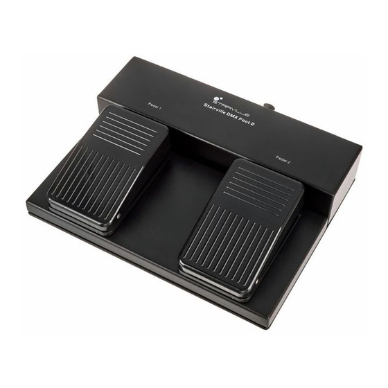
Connections and operating elements Connections and operating elements Top view DMX Foot 2 Pedal 1 Pedal 2 ö DMX Foot 2 DMX Controller... - Page 17 Connections and operating elements 1 [Pedal 1] Foot switch for controlling the assigned presets in the device memory 2 [Pedal 2] Foot switch for controlling the assigned presets in the device memory Rear panel Menu Enter Power INPUT Down DMX IN DMX OUT &...
- Page 18 Connections and operating elements 5 [DMX IN] DMX input, designed as 3-pin XLR chassis-mounted plug 6 [DMX OUT] DMX output, designed as 3-pin XLR panel socket 7 Display 8 Key panel [MENU] Activates the main menu or quits an submenu [UP] Increases the displayed value by one or changes between the menu levels [DOWN]...
-
Page 19: Operating
Operating Operating Press [Up] or [Down] to toggle between the menu items. Confirm the selection with [Enter] to restore the selected menu item. Use [Up] and [Down] to change the respectively displayed value. Press [Menu] to accept the selection and exit the open menu. DMX Foot 2 DMX Controller... -
Page 20: Assigning Dmx Channels And Addresses
Operating 7.1 Assigning DMX channels and addresses To assign the DMX channels and DMX addresses of the presets, proceed as follows: Preset selection Press [Up] or [Down] until the display shows ‘PROGRAM’ and confirm with [Enter]. Press [Up] or [Down] until the display shows ‘Preset Select’ and confirm with [Enter]. Use [Up] or [Down] to select a value between ‘01’... -
Page 21: Deleting Dmx Channels And Values
Operating You can set the DMX values for each channel via the menu or record a present DMX signal at the DMX input. 7.2 Deleting DMX channels and values To reset the DMX channels and DMX values of the individual presets, proceed as follows: Press [Up] or [Down] until the display shows ‘PROGRAM’... -
Page 22: Pedal Settings
Operating 7.3 Pedal settings 7.3.1 Assigning preset To assign a preset to the footswitches [Pedal 1] and [Pedal 2], proceed as follows: Press [Up] or [Down] until the display shows ‘Pedal1 Setup’ or ‘Pedal2 Setup’ and confirm with [Enter]. Press [Up] or [Down] until the display shows ‘PEDAL1 Preset’ or ‘PEDAL2 Preset’ and con‐ firm with [Enter]. - Page 23 Operating 7.3.2 Footswitch response To assign the response of the footswitches [Pedal 1] and [Pedal 2], proceed as follows: Press [Up] or [Down] until the display shows ‘Pedal1 Setup’ or ‘Pedal2 Setup’ and confirm with [Enter]. Press [Up] or [Down] until the display shows ‘PEDAL1 Preset’ or ‘PEDAL2 Preset’ and con‐ firm with [Enter].
- Page 24 Operating 7.3.3 Fade time (fade in or fade out) To assign the fade time ( ‘Fade In’ or ‘Fade Out’ ) of the footswitches [Pedal 1] and [Pedal 2] proceed as follows: Fade In Press [Up] or [Down] until the display shows ‘Pedal1 Setup’ or ‘Pedal2 Setup’ and confirm with [Enter].
- Page 25 Operating 7.3.4 Hold time Setting hold time To set the hold time of the footswitches [Pedal 1] and [Pedal 2], proceed as follows: Press [Up] or [Down] until the display shows ‘Pedal1 Setup’ or ‘Pedal2 Setup’ and confirm with [Enter]. Use [Up] or [Down] to select the menu item ‘PEDAL1 HodTime’...
-
Page 26: System Settings
Operating The Hold time setting is only available for the response type ‘Toggle’ . 7.4 System settings 7.4.1 LTP/HTP The device has two options for combining DMX signals into a new signal: LTP and HTP. LTP (Latest Takes Precedence) In LTP mode, the last DMX value has priority. Press [Up] or [Down] until the display shows ‘System Setup’... - Page 27 Operating HTP (High Take Precedence In HTP mode, the highest DMX value has priority. Modus) Press [Up] or [Down] until the display shows ‘System Setup’ and confirm with [Enter]. Use [Up] or [Down] to select the menu item ‘LTP / HTP’ confirm with [Enter]. Use [Up] or [Down] to select the menu item ‘HTP’...
- Page 28 Operating 7.4.3 Key lock Proceed as follows to adjust the key lock: Press [Up] or [Down] until the display shows ‘System Setup’ and confirm with [Enter]. Use [Up] or [Down] to select the menu item ‘Display Lock’ and confirm with [Enter]. Use [Up] or [Down] to select the menu item ‘ON’...
- Page 29 Operating 7.4.4 Combining DMX signals (Merge) In MERGE mode, the DMX signals fo the modes HTP or LTP are combined to form a new signal. Press [Up] or [Down] until the display shows ‘System Setup’ and confirm with [Enter]. Use [Up] or [Down] to select the menu item ‘Merge DMX In’ and confirm with [Enter]. Use [Up] or [Down] to select ‘Merge DMX In’...
- Page 30 Operating 7.4.5 Software version To display the software version, proceed as follows: Press [Up] or [Down] until the display shows ‘INFO’ and confirm with [Enter]. ð The display shows ‘--INFO--’ . Press [Enter]. ð The display shows the current software version. DMX Foot 2 DMX Controller...
-
Page 31: Menu Overview
Operating 7.5 Menu overview PROGRAM Pedal1 Setup Pedal2 Setup System Setup INFO Preset Select PEDAL1 Preset PEDAL2 Preset LTP / HTP --INFO-- Version VX.X ENTER to save Preset Save Disp Backlight PEDAL1 Mode PEDAL2 Mode MENU to back Toggle Toggle Channel Flash Flash... -
Page 32: Technical Specifications
Technical specifications Technical specifications Number of DMX channels Input connections Power supply 12 V plug-in power supply DMX control XLR chassis plug, 3-pin Output connections DMX control XLR chassis socket, 3-pin Power supply External power adapter, 100 - 240 V 50/60 Hz Operating voltage 12 V... - Page 33 Technical specifications Further information Variant group Stairville LED Preset function External storage option DMX universes max. control channels Ethernet DMX Foot 2 DMX Controller...
-
Page 34: Plug And Connection Assignment
Plug and connection assignment Plug and connection assignment Introduction This chapter will help you select the right cables and plugs to connect your valuable equip‐ ment so that a perfect light experience is guaranteed. Please take our tips, because especially in ‘Sound & Light’ caution is indicated: Even if a plug fits into a socket, the result of an incorrect connection may be a destroyed DMX controller, a short circuit or ‘just’... -
Page 35: Protecting The Environment
Protecting the environment Protecting the environment Disposal of the packaging mate‐ rial For the transport and protective packaging, environmentally friendly materials have been chosen that can be supplied to normal recycling. Ensure that plastic bags, packaging, etc. are properly disposed of. Do not just dispose of these materials with your normal household waste, but make sure that they are collected for recycling. - Page 36 Notes DMX Foot 2 DMX Controller...
- Page 37 Notes DMX Foot 2 DMX Controller...
- Page 38 Notes DMX Foot 2 DMX Controller...
- Page 40 Musikhaus Thomann · Hans-Thomann-Straße 1 · 96138 Burgebrach · Germany · www.thomann.de...
Need help?
Do you have a question about the STAIRVILLE DMX Foot 2 and is the answer not in the manual?
Questions and answers