Table of Contents
Advertisement
WARNING
Improper installation, adjustment, alteration,
service or maintenance can cause property
damage, injury or death, and could cause
exposure to substances which have been
determined by various state agencies to cause
cancer, birth defects or other reproductive
harm. Read the installation, operating and
maintenance instructions thoroughly before
installing or servicing this equipment.
WARNING
This unit contains R-410A high pressure
refrigerant. Hazards exist that could result in
personal injury or death. Installation,
maintenance, and service must only be
performed by an HVAC technician qualified in
R-410A refrigerant and using proper tools and
equipment. Due to much higher pressure of
R-410A refrigerant, DO NOT USE service
equipment or tools designed for refrigerants
other than R410A.
PLEASE BE SURE TO LEAVE IT WITH THE OWNER WHEN YOU LEAVE THE JOB.
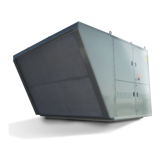
INSTALLATION AND SERVICE MANUAL
commercial packaged ventilation system units
model MPR
THIS MANUAL IS THE PROPERTY OF THE OWNER.
MCP15-500.9
(for units with 24 digit model numbers)
WARNING
FIRE OR EXPLOSION HAZARD
Failure to follow safety warnings exactly could
result in serious injury, death or property
damage.
Be sure to read and understand the installation,
operation and service instructions in this manual.
Improper installation, adjustment, alteration,
service or maintenance can cause serious
injury, death or property damage.
Do not store or use gasoline or other
flammable vapors and liquids in the vicinity
of this or any other appliance.
WHAT TO DO IF YOU SMELL GAS:
• Do not try to light any appliance.
• Do not touch any electrical switch, do
not use any phone in your building.
• Leave the building immediately.
• Immediately call your gas supplier from
a phone remote from the building.
Follow the gas supplier's instructions.
• If you cannot reach your gas supplier,
call the fire department.
Installation and service must be performed by
a qualified installer, service agency or the gas
supplier.
Inspection on Arrival
1. Inspect unit upon arrival. In case of damage, report it
immediately to transportation company and your local
factory sales representative.
2. Check rating plate on unit to verify that power supply meets
available electric power at the point of installation.
3. Inspect unit upon arrival for conformance with description
of product ordered (including specifications where
applicable).
MCP15-500.9
5H0816400000
October, 2020
1
Advertisement
Table of Contents

Related Manuals for Modine Manufacturing MPR Series


Summary of Contents for Modine Manufacturing MPR Series
-
Page 1: Inspection On Arrival
MCP15-500.9 5H0816400000 October, 2020 INSTALLATION AND SERVICE MANUAL commercial packaged ventilation system units model MPR (for units with 24 digit model numbers) WARNING FIRE OR EXPLOSION HAZARD Failure to follow safety warnings exactly could result in serious injury, death or property damage. -
Page 2: Special Precautions
A complete WARNING replacement parts list may be obtained by contacting Modine Manufacturing Company. Refer to the rating plate on the appliance for complete appliance model Failure to follow proper lifting instructions and applicable number, serial number, and company address. Any... -
Page 3: Table Of Contents
0.028 m3/min Special Design Requests Modine Manufacturing Company will sometimes build units with special features as requested by the customer. This manual only covers standard features and does not include any changes made for special feature requests by the customer. -
Page 4: Unit Location
UNIT LOCATION / COMBUSTIBLE MATERIAL & SERVICE CLEARANCES UNIT LOCATION Figure 4.1 - Combustible Material & Service Clearances (continued next page) DANGER B- AND C-CABINET UNITS WITHOUT ENERGY RECOVERY Appliances must not be installed where they may be exposed to potentially explosive or flammable atmosphere. FIELD INSTALLED ACCESSORY 36.0... - Page 5 COMBUSTIBLE MATERIAL & SERVICE CLEARANCES Figure 5.1 - Combustible Material & Service Clearances (continued from previous page) D-CABINET UNITS WITHOUT ENERGY RECOVERY D-CABINET UNITS WITH ENERGY RECOVERY FIELD INSTALLED FIELD INSTALLED ACCESSORY ACCESSORY 36.00 SEE NOTE 2 36.0 SEE NOTE 2 RAINHOOD RAINHOOD SEE NOTE 4...
-
Page 6: Installation
ROOF CURB INSTALLATION / GENERAL RIGGING INSTRUCTIONS General Rigging Instructions Roof Curb Installation WARNING An optional roof curb is available to simplify site preparation and raise the unit above roof water and snow level for drainage. It can be installed in advance of the unit. The curb Failure to follow proper lifting instructions and applicable is shipped knocked down with separate instructions (Literature safety procedures could result in property damage, serious... -
Page 7: Duct Installation
UNIT AND DUCT INSTALLATION Figure 7.1 - Typical Rigging for Model MPR to the unit, include a spreader bar as illustrated in Figure 7.1. Avoid twisting or uneven lifting of the unit. The cable B-CABINET UNIT - WITHOUT ENERGY RECOVERY length from the lifting point on the unit to the spreader bar C-CABINET UNIT - ALL should always be longer than the distance between the... -
Page 8: Condensate Drain Installation/Utility Connections
CONDENSATE DRAIN INSTALLATION/UTILITY CONNECTIONS Evap Condensate Drain Trap Installation Figure 8.2 - Evap Condensate Drain Trap Installation IMPORTANT Note: All piping components shown are supplied by others. TRAP HEIGHT (6" MINIMUM) A properly designed drain with trap must be installed immediately after the unit evaporator coil condensate drain CAPPED CLEANOUT... -
Page 9: Electrical Connections
ELECTRICAL CONNECTIONS Electrical Connections WARNING For field wiring to the factory terminal strip, the terminal strip connections are designed to clamp down on the wires. roltage. To properly connect the wires to the terminal strip: Disconnect power supply before making wiring •... - Page 10 ELECTRICAL CONNECTIONS / GAS CONNECTIONS • Space CO Sensor REVIEW BEFORE PROCEEDING This sensor is required on all units that have demand based ventilation control. The sensor is to be mounted in the space at a height of approximately 5 feet from the THIS SECTION APPLIES TO UNITS WITH floor.
-
Page 11: Gas Connections
GAS CONNECTIONS W.C. for propane gas and should not drop below 6.0" W.C. Table 11.1 - Gas Heating Piping Connection Sizes when the unit is operating. When sizing the inlet gas pipe Cabinet Size Gas Type Furnace Size Gas Connection diameter, make sure that the unit supply pressure can be (Digit 6) (Digit 17) j... -
Page 12: Vent Terminals And Combustion Air Hoods
GAS HEATING OPTION VENT TERMINALS AND COMBUSTION AIR HOODS Vent Terminals and Combustion Air Hoods Section A: Non-Condensing B or C-Cabinet Furnaces Do not operate the units without the factory supplied and/or shipped loose power exhauster vent termination(s) and/or • Review Table 12.1 to verify this is the correct section for combustion air hoods if applicable. - Page 13 GAS HEATING OPTION VENT TERMINALS AND COMBUSTION AIR HOODS Section C: Condensing B or C-Cabinet Furnaces Figure 13.2 - Vent Terminal for Condensing Gas Furnace Option (C-Cabinet) • Review Table 12.1 to verify this is the correct section for the unit and furnace type installed. If not, refer to the proper section as indicated for the unit as configured.
- Page 14 GAS HEATING OPTION VENT TERMINALS AND COMBUSTION AIR HOODS Section E: Hybrid Condensing & Non-Condensing D-Cabinet Furnaces • Review Table 12.1 to verify this is the correct section for the unit and furnace type installed. If not, refer to the proper section as indicated for the unit as configured.
-
Page 15: Gas Heating Option Condensate Drains & Traps
GAS HEATING OPTION CONDENSATE DRAIN AND TRAP INSTALLATION Furnace Condensate Drain/Trap Installation Figure 15.1 - Furnace Condensate Drain and Float Switch Location j REVIEW BEFORE PROCEEDING THIS SECTION APPLIES TO UNITS WITH OPTIONAL CONDENSING OR HYBRID GAS HEAT (MODEL DIGIT 17=2 OR 3) Furnace Condensate PER TABLE 12.1. -
Page 16: Hot Water Piping Connections
HOT WATER PIPING CONNECTIONS • On 3-way valve control configurations, include a balancing REVIEW BEFORE PROCEEDING valve between the supply line and control valve to balance the system. THIS SECTION APPLIES TO UNITS WITH • Include a hose bib drain valve on the bottom of the supply manifold to allow for periodic flushing of the system to OPTIONAL HOT WATER HEAT remove sediments from the coil. - Page 17 PAGE INTENTIONALLY LEFT BLANK MCP15-500.9...
-
Page 18: Start-Up Procedure
START-UP PROCEDURE General WARNING Check that fuses or circuit breakers are in place and sized WARNING correctly. Verify that all wiring is secure and properly protected. Trace circuits to ensure that the unit has been wired according to When the dead front disconnect switch(es) (for main unit and/or powered convenience outlet option) is in the the wiring diagram. -
Page 19: Blower Adjustments
START-UP PROCEDURE - CONTINUED 17. Check that the evaporator drain pan drain trap has been 27. For units equipped for dual power supply sources, the unit primed with water. should be started separately on the main power feed and again on the auxiliary power feed to verify proper unit and 18. - Page 20 START-UP PROCEDURE - CONTINUED Blower Adjustments – Direct Drive Fans Figure 20.1 - Direct Drive Blower Example All direct drive supply fan speed adjustments can be performed with the Modine Control System programmable microprocessor controller. There are two ways to access the menus: DIRECT DRIVEN BLOWER (DUAL BLOWER SHOWN) Using the user interface on the main unit controller.
-
Page 21: Airflow Proving Switch And Dirty Filter Switch
START-UP PROCEDURE - CONTINUED Blower Adjustments – Belt Drive Fans Setting the Air Flow Proving or Dirty Filter Switch All belt drive supply fan and, if applicable, exhaust fan speed Ensure that the unit filters are clean. Replace if necessary. adjustments can be made with the adjustable sheave on the Using the Modine Control System controller interface, start blower motor as follows:... -
Page 22: Checking Refrigerant Charge
START-UP PROCEDURE - CONTINUED Checking Refrigerant Charge b. Measure the temperature of the suction line at a point WARNING near where the pressure reading was taken. c. Subtract the saturated temperature from the measured suction line temperature to determine the evaporator This unit contains R-410A high pressure refrigerant. -
Page 23: Gas Heating Option
START-UP PROCEDURE - CONTINUED Ensure that the supply fan blower is operating at the proper REVIEW BEFORE PROCEEDING airflow and adjust the Modine Control Systemc control setpoint to create a call for heat. Refer to the Controls Manual, literature #MCP74-525 for instructions on changing THIS SECTION APPLIES TO UNITS WITH the setpoint. - Page 24 START-UP PROCEDURE - CONTINUED Press and hold Button #1 on the modulating valve Save the setting by simultaneously holding Buttons until the LED lights solid red, then release. #1 and #2 until the LED turns OFF. If this is not performed within 5 minutes, the control will default With the valve now in the high fire setting mode, to the previously saved settings and return to normal...
- Page 25 START-UP PROCEDURE - CONTINUED If a lockout error condition occurs, or the MODE button is Figure 25.3 - Furnace Primary/Secondary Locations depressed for more than 4 seconds, or there is no push button activity for 30 minutes, then the Checkout Test mode will be exited.
- Page 26 START-UP PROCEDURE - CONTINUED Figure 26.1 - Gas Heat Option Gas Controls - B-Cabinet Sized Units 13. Compartment strip heater/thermostat Power exhauster Vent differential pressure proving switch (94% efficiency furnace only - not Maxitrol EXA STAR modulating gas valve Direct spark ignitor pictured) Main combination gas valve Manifold pressure tap on manifold tee...
- Page 27 START-UP PROCEDURE - CONTINUED Figure 27.1 - Gas Heat Option Gas Controls - C-Cabinet Sized Units Left Furnace Right Furnace (Secondary) (Primary) Power exhauster Not Applicable Maxitrol EXA STAR modulating gas valve (right-hand furnace Vent differential pressure proving switch only) 10.
- Page 28 START-UP PROCEDURE - CONTINUED Figure 28.1 - Gas Heat Option Gas Controls - D-Cabinet Sized Units - 800,000 Btu/hr and Smaller (81% Eff) Power exhauster Vent differential pressure proving switch Maxitrol EXA STAR modulating gas valve (primary furnace only) Direct spark ignitor Main combination gas valve Manifold pressure tap on manifold tee (primary furnace only) High limit control (hidden behind piping as shown)
- Page 29 START-UP PROCEDURE - CONTINUED Figure 29.1 - Gas Heat Option Gas Controls - D-Cabinet Sized Units - 900,000 Btu/hr and Larger (81% Eff) Secondary Furnace “B” k Primary Furnace k Refer to Figure 25.3 for location of furnace positions. Refer to Figure 28.1 for idenfication of furnace components.
- Page 30 START-UP PROCEDURE - CONTINUED Figure 30.1 - Gas Heat Option Gas Controls - D-Cabinet Units - 620,000 Btu/hr and Smaller (94% Eff) Power exhauster Direct spark ignitor Maxitrol EXA STAR modulating gas valve (primary furnace only) Manifold pressure tap on manifold tee (primary furnace only) Main combination gas valve 10.
- Page 31 START-UP PROCEDURE - CONTINUED Figure 31.1 - Gas Heat Option Gas Controls - D-Cabinet Units - 850,000 Btu/hr and Larger (Hybrid 87% Eff) Secondary Furnace “B” k Primary Furnace k Refer to Figure 25.3 for location of furnace positions. For identification of furnace components, refer to Figure 28.1 for the 81% efficient modules on the bottom and Figure 30.1 for the condensing modules on the top.
-
Page 32: Energy Recovery Option (B And D-Cabinet Units Only)
START-UP PROCEDURE - CONTINUED THE FOLLOWING SECTION APPLIES ONLY TO B- AND D-CABINET REVIEW SIZED UNITS WITH OPTIONAL ENERGY RECOVERY EXHAUST (MODEL NOMENCLATURE DIGIT 6=B OR D, DIGIT 7=B OR E). BEFORE PROCEEDING IF THE UNIT DOES NOT HAVE THIS OPTION, SKIP TO PAGE 34.j j If the unit is a C-cabinet size and has energy recovery exhaust, refer to the latest revision of literature #MCP15-520 for the Start-Up Procedure for the Model ERM Energy Recovery Module. - Page 33 UNIT COMPONENT IDENTIFICATION / LOCATION Figure 33.1 - Controls Cabinet - Energy Recovery Section (B and D-Cabinet only, if equipped) j (S) Energy recovery wheel (S) Controls/power compartment with terminal strips (B-Cabinet) (S) Controls compartment with terminal strips (see #3) (D-Cabinet) (S) Power compartment with terminal strips (see #2) (D-Cabinet) (S) Carel pCOxs microprocessor controller (S) Exhaust fan motor circuit fuses k...
-
Page 34: Unit Features/Options Location Drawings
UNIT COMPONENT IDENTIFICATION / LOCATION ALL FIGURES ON THIS PAGE ARE FOR B- AND C-CABINET SIZED UNITS Figure 34.1 - Blower/Evaporator/Filter/Damper Sections j Figure 34.2 - Condenser Section j 20 21 1 (S) Condenser fan housing 1 (O) GFCI convenience outlet (not shown here, refer to Figure 26.1) 2 (S) Condenser fan motors 2 (S) Blower door switch 3 (S) Refrigerant filter/dryer assembly... - Page 35 UNIT COMPONENT IDENTIFICATION / LOCATION ALL FIGURES ON THIS PAGE ARE FOR D-CABINET SIZED UNITS Figure 35.1 - Compressor/Condenser/Blower/Evaporator/Filter/Damper Sections j (S) Blower door switch 17. (O) Return air damper 18. (O) Modulating damper actuator (S) Airflow proving switch (not shown, located on opposite side) (S) Direct drive supply fan(s)/motor(s) 19.
- Page 36 UNIT COMPONENT IDENTIFICATION / LOCATION Figure 36.1 - Typical Controls Cabinet - B-Cabinet Sized Units j Left Panel Main Panel Right Panel Ref: 3H039747 Ref: 3H038664 Ref: 3H038665 27 28 MAIN PANEL COMPRESSOR CONTROL PANEL (LEFT SIDE) (S) Power distribution block 24.
- Page 37 UNIT COMPONENT IDENTIFICATION / LOCATION Figure 37.1 - Typical Controls Cabinet - C-Cabinet Sized Units j Left Panel Main Panel Right Panel Ref: 3H039728 Ref: 3H038318 Ref: 3H038319 MAIN PANEL 23. (O) Auxiliary / Supplementary electric heat fuse holder 24. (O) Power exhaust motor fuse holder (S) Power distribution block (S) High voltage wiring terminal strip with ground terminals 25.
- Page 38 UNIT COMPONENT IDENTIFICATION / LOCATION Figure 38.1 - Typical Controls Cabinet - D-Cabinet Sized Units j Main Panel Ref: 3H039503 (O) Remote shutdown relay (O) Supply fan enable relay (for units with two supply fan VFD’s) (S) Carel EVD Ultracap - Circuit #1 (S) Carel EVD Ultracap - Circuit #2 (S) Low voltage terminal strip (S) Controls secondary circuit breaker...
- Page 39 UNIT COMPONENT IDENTIFICATION / LOCATION Figure 39.1 - Typical Power Cabinet - D-Cabinet Sized Units j Left Panel Main Panel Right Panel Ref: 3H039503 Ref: 3H039486 Ref: 3H039485 LEFT SIDE POWER PANEL 12. (S) Compressor Circuit Breakers 13. (S) Compressor Contactors (S) 24V Control Transformer (O) Gas Heat Control Transformer Secondary Circuit Breaker 14.
-
Page 40: Dimensions/Weights
DIMENSIONS - B-CABINET SIZE UNIT (NO ENERGY RECOVERY) Figure 40.1 - Unit Dimensions (inches) CONDENSING SECTION FAN QUANTITY: (2) FOR 7 AND 10 TON UNITS (3) FOR 13 , 15, AND 20 TON UNITS (4) 1.5" LIFTING EYE BOLTS (EACH CORNER OF UNIT) 55.90 ACCESSORY RAINHOOD AND BIRDSCREEN... - Page 41 DIMENSIONS - B-CABINET UNIT BASE/ROOF CURB (NO ENERGY RECOVERY) Figure 41.1 - Unit Base Dimensions (inches) 100.00 95.22 UNIT ACCESS SIDE 2.39 5.72 9.76 10.73 2.00" DIA. ELECTRICAL ENTRY HOLE 2.39 10.50 2.39 1.75" DIA. RETURN/ FURNACE CONDENSATE EXHAUST DRAIN LINE HOLE 49.22 54.00 40.00...
-
Page 42: B-Cabinet Size Unit With Energy Recovery
DIMENSIONS - B-CABINET SIZE UNIT (WITH ENERGY RECOVERY) Figure 42.1 - Unit Dimensions (inches) CONDENSING SECTION ENERGY RECOVERY ENERGY RECOVERY FAN QUANTITY: WHEEL ECONOMIZER EXHAUST AIR (2) FOR 7 AND 10 TON UNITS BYPASS DAMPER RAINHOOD (3) FOR 13, 15, AND 20 TON UNITS (4) 1"... - Page 43 DIMENSIONS - B-CABINET UNIT BASE/ROOF CURB (W/ ENERGY RECOVERY) Figure 43.1 - Unit Base Dimensions (inches) 176.00 172.50 102.25 168.00 UNIT ACCESS SIDE 2.39 163.22 9.76 2.00" DIA. 10.73 ELECTRICAL 5.72 ENTRY HOLE 2.39 10.50 2.39 1.75" DIA. FURNACE RETURN/ 49.22 43.72 54.00...
- Page 44 DIMENSIONS - C-CABINET SIZE UNIT Figure 44.1 - Unit Dimensions (inches) CONDENSING SECTION FAN QUANTITY: (2) FANS FOR 15 TON UNIT (3) FANS FOR 20 THRU 30 TON UNITS (4) 1.50" LIFTING EYE BOLTS (EACH CORNER OF UNIT) 65.92 60.11 107.12 ACCESSORY RAINHOOD AND BIRDSCREEN...
- Page 45 DIMENSIONS - C-CABINET SIZE UNIT BASE / ROOF CURB Figure 45.1 - Unit Base Dimensions (inches) 111.28 2.00" DIA. 106.22 2.53 ELECTRICAL UNIT ACCESS ENTRY HOLE SIDE 2.53 9.24 9.24 4.61 4.61 HOT WATER PIPING ENTRANCE 13.77 (UNITS WITH HOT 17.09 WATER HEAT ONLY) 6.60...
-
Page 46: D-Cabinet Size Unit Without Energy Recovery
DIMENSIONS - D-CABINET SIZE UNIT Figure 46.1 - Unit Dimensions (inches) 103.07 CONDENSING SECTION FAN QUANTITY: (4) FANS FOR 30 AND 40 TON UNIT (6) FANS FOR 52 AND 60 TON UNITS ACCESSORY RAINHOOD AND BIRDSCREEN (FIELD INSTALLED ACCESSORY) 180.63 40.36 CONDENSING SECTION... - Page 47 DIMENSIONS - D-CABINET SIZE UNIT BASE / ROOF CURB Figure 47.1 - Unit Base Dimensions (inches) 180.00 172.00 4.00 4.00 18.26 8.52 21.89 34.24 SUPPLY AIR RETURN AIR 92.75 100.75 OPENING OPENING (IF 60.12 SELECTED) 4.00 HIGH VOLT POWER CABINET THIS SIDE 8.00 25.00 4.39...
-
Page 48: D-Cabinet Size Unit With Energy Recovery
DIMENSIONS - D-CABINET SIZE UNIT (WITH ENERGY RECOVERY) Figure 48.1 - Unit Dimensions (inches) 103.07 CONDENSING SECTION FAN QUANTITY: (4) FANS FOR 30 AND 40 TON UNIT (6) / (8) FANS FOR 52 AND 60 TON UNITS ACCESSORY RAINHOOD AND BIRDSCREEN (FIELD INSTALLED ACCESSORY) 306.10 180.73... - Page 49 DIMENSIONS - D-CABINET UNIT BASE/ROOF CURB (W/ENERGY RECOVERY) Figure 49.1 - Unit Base Dimensions (inches) 263.68 255.68 ERM CONTROL PANEL ON THIS SIDE 4.00 8.50 18.25 21.89 34.25 86.48 25.00 88.07 SUPPLY AIR EXHAUST/ 4.00 4.00 OPENING RETURN AIR OPENING 92.75 100.75 60.12 80.75...
-
Page 50: C-Cabinet Size Unit
BASE MODEL WEIGHTS Table 50.1 - Approximate Base Model Weight - (lbs.) Weights shown are approximate and may not include all features included with the selected unit. For more specific weight totals for the selected unit(s), refer to either the Breeze AccuSpec Submittal Package or the Order Detail. Cabinet Size Cabinet Size Section... -
Page 51: Option And Accessory Pressure Drop Tables
OPTION AND ACCESSORY PRESSURE DROP TABLES Table 51.1 - Pressure Drop Data - B-Cabinet Sized Unit Supply Fan j Feature 7 & 10 Ton 0.06 0.08 0.10 0.13 0.16 0.19 0.22 0.25 0.28 0.35 0.42 0.50 0.58 0.67 0.76 Evaporator Coil 13 &... - Page 52 OPTION AND ACCESSORY PRESSURE DROP TABLES Table 52.1 - Pressure Drop Data - C-Cabinet Sized Unit Supply Fan jk Feature Evaporator Coil 0.11 0.15 0.18 0.21 0.25 0.29 0.32 0.36 0.40 0.44 0.49 0.53 0.58 0.67 0.87 Unit Hot Gas Reheat Coil 0.05 0.05 0.05...
- Page 53 OPTION AND ACCESSORY PRESSURE DROP TABLES Table 53.1 - Pressure Drop Data - D-Cabinet Sized Unit Supply Fan jk Feature 30 & 40 Ton 0.17 0.24 0.32 0.41 0.51 0.62 0.73 0.86 0.99 Evaporator Coil 52 & 60 Ton 0.14 0.18 0.23 0.29...
-
Page 54: Maintenance
MAINTENANCE General Maintenance Check that the supply voltage matches the unit supply WARNING voltage listed on the Unit Serial Plate. Verify that all wiring is secure and properly protected. Trace circuits to insure that the unit has been wired according to the When the dead front disconnect switch(es) (for main unit wiring diagram. - Page 55 MAINTENANCE - CONTINUED Air Filters Cooling Coil Drain Pan and Drain System If the unit is supplied with a dirty filter switch, replace the air The drain pan, trap, and drain pipe must be cleaned regularly to filters any time the Modine Control System controller provides a avoid blockage that can reduce or stop water flow as follows: dirty filter alarm notice.
- Page 56 MAINTENANCE - CONTINUED Duct Furnace Hot Water Heat Coil Maintenance When providing annual maintenance for the duct furnace, keep If the unit is supplied with a factory installed hot water heat coil, the unit free from dust, dirt, grease and foreign matter. Pay check the following: particular attention to: Periodically, inspect the coils for signs of corrosion and...
- Page 57 MAINTENANCE - CONTINUED Energy Recovery Exhaust Assembly Exhaust/Barometric Relief Dampers If the unit is equipped with a Modine supplied Energy Recovery Exhaust section, check the following: If the unit is equipped with an exhaust fan (Digit 7=B, C, E, or F) or barometric relief dampers (Digit 7=R), check that the The energy recovery wheel drive belt is a linked belt that dampers are clean and manually open/close freely.
-
Page 58: Service & Troubleshooting
Modine Manufacturing Company. Refer to the rating plate on the unit for complete unit model number, serial To check most of the Possible Remedies in the troubleshooting number, and company address. - Page 59 SERVICE & TROUBLESHOOTING - CONTINUED Table 59.1 - Troubleshooting (Continued) Trouble Possible Cause Possible Remedy F. Compressor(s) Do 1. See Problems “A” and “B” 1. See Problems “A” and “B” Not Operate 2. Controls are in Unoccupied mode 2. Wait for Occupied mode or override 3.
- Page 60 SERVICE & TROUBLESHOOTING - CONTINUED Table 60.1 - Primary Furnace Control Board (VB1200) Error Codes (Applies to B-, C-, and D-Cabinet Units with Gas Heat Option furnace model number Digit 11=6 or 8) j Display Code Description Additional comments and notes Board Failure (Up to 10 sec @ power up) Verify 24 VAC signal input at connector J6.
- Page 61 SERVICE & TROUBLESHOOTING - CONTINUED Table 61.1 - Furnace Secondary Control Board (VB1201) Error Codes (Applies only to C- and D-Cabinet Units with Gas Heat Option furnace model number Digit 11=8) j Color Flashes Condition Error Conditions No power to the control board Steady On Hard lockout on control fault or no 24 VAC.
-
Page 62: Serial Plates
MODEL IDENTIFICATION & SERIAL PLATES Model Identification Depending on options included, the unit may have more than one Serial Plate. Figures 62.1 and 62.2 show the Serial Plate for the main unit, while Figures 62.3 and 62.4 show the Serial Plate for the gas heat option. When servicing, repairing or replacing parts on these units, locate the model Serial Plate of the unit and always give the complete Model Number and Serial Number of the unit. -
Page 63: Model Nomenclature
MODEL NOMENCLATURE Model Nomenclature As noted in the previous section, units may have more than one Serial Plate. If the unit has the gas heat option, the furnace will have its own model number separate from the main unit. • Table 63.1 shows the nomenclature for the gas heat section option. - Page 64 MODEL NOMENCLATURE - MODEL MPR Table 64.1 - Model Nomenclature - Main Unit Cabinet Digits Indicates Description Value 1, 2, 3 Unit Type Commercial Packaged Ventilation Unit ● ● ● 7, 10, or 13 ton 07, 10, 13 ● 15 or 20 ton 15, 20 ●...
- Page 65 MODEL NOMENCLATURE - MODEL MPR - CONTINUED Table 65.1 - Model Nomenclature - Main Unit (Continued from previous page) Cabinet Digits Indicates Description Value 208V/3ph ● ● ● 230V/3ph ● ● ● Unit Supply Voltage 460V/3ph ● ● ● 575V/3ph (not available on 52/60 ton D-Cabinet) ●...
- Page 66 MODEL NOMENCLATURE - MODEL MPR - CONTINUED Table 66.1 - Model Nomenclature - Main Unit (Continued from previous page) Cabinet Digits Indicates Description Value None (or Not Applicable for C-Cabinet) ● ● 28” ● Klingenburg Aluminum 36” ● 4A Molecular Sieve 48”...
- Page 67 PAGE INTENTIONALLY LEFT BLANK MCP15-500.9...
-
Page 68: Commercial Warranty
Burners High Intensity Infrared Units Sheet Metal Parts All Products As Modine Manufacturing Company has a continuous product improvement program, it reserves the right to change design and specifications without notice. Modine Manufacturing Company 1500 DeKoven Avenue Racine, WI 53403 Phone: 1.800.828.4328 (HEAT)
Need help?
Do you have a question about the MPR Series and is the answer not in the manual?
Questions and answers