Table of Contents
Advertisement
Quick Links
WARNING
Improper installation, adjustment, alteration,
service or maintenance can cause property
damage, injury or death, and could cause
exposure to substances which have been
determined by various state agencies to cause
cancer, birth defects or other reproductive harm.
Read the installation, operating and maintenance
instructions thoroughly before installing or
servicing this equipment.
IMPORTANT
1. The use of this manual is specifically intended
for a qualified installation and service agency.
A qualified installation and service agency must
perform all installation and service of these
appliances.
2. ZCV and ZCF units with DX evaporator coils
contain the refrigerant R-410A. Review the
R-410A Material Safety Data Sheet (MSDS) for
hazards and first aid measures.
3. Refrigerant charging should only be carried out
by an EPA-certified air conditioning contractor.
PLEASE BE SURE TO LEAVE IT WITH THE OWNER WHEN YOU LEAVE THE JOB.
INSTALLATION AND SERVICE MANUAL
THIS MANUAL IS THE PROPERTY OF THE OWNER.
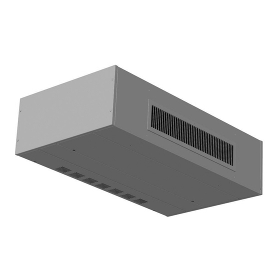
Varsity
Ceiling Unit Ventilator
TM
Models ZCV and ZCF
WARNING
This unit contains R-410A high pressure refrigerant.
Hazards exist that could result in personal injury
or death. Installation, maintenance, and service
must only be performed by an HVAC technician
qualified in R-410A refrigerant and using proper
tools and equipment. Due to much higher pressure
of R-410A refrigerant, DO NOT USE service
equipment or tools designed for refrigerants other
than R410A.
Inspection On Arrival
1. Inspect unit upon arrival. In case of damage, report it
immediately to transportation company and your local factory
sales representative.
2. Check rating plate on unit to verify that power supply meets
available electric power at the point of installation.
3. Inspect unit received for conformance with description of
product ordered (including specifications where applicable).
AIR14-501.2
5H1035970002
December, 2019
Advertisement
Table of Contents

Related Manuals for Modine Manufacturing Varsity ZCV Series


Summary of Contents for Modine Manufacturing Varsity ZCV Series
-
Page 1: Inspection On Arrival
AIR14-501.2 5H1035970002 December, 2019 INSTALLATION AND SERVICE MANUAL Varsity Ceiling Unit Ventilator Models ZCV and ZCF WARNING WARNING Improper installation, adjustment, alteration, This unit contains R-410A high pressure refrigerant. service or maintenance can cause property Hazards exist that could result in personal injury damage, injury or death, and could cause or death. -
Page 2: Table Of Contents
SPECIAL PRECAUTIONS SPECIAL PRECAUTIONS CAUTION THE INSTALLATION AND MAINTENANCE INSTRUCTIONS IN THIS MANUAL MUST BE FOLLOWED TO PROVIDE 1. Ensure that the supply voltage to the appliance, as SAFE, EFFICIENT, AND TROUBLE-FREE OPERATION. IN indicated on the serial plate, is not 5% less than the rated ADDITION, PARTICULAR CARE MUST BE EXERCISED voltage. -
Page 3: Metric) Conversion Factors
UNIT LOCATION Table 3.1 - SI (Metric) Conversion Factors 8. For units with outside air, inspect the wall sleeve and louver installation for gaps that would allow leakage of outdoor air To Convert Multiply By To Obtain To Convert Multiply By To Obtain into the space. -
Page 4: Piping Installation
START-UP PROCEDURE Piping Installation - Chilled/Hot Water Coils Figure 4.1 - Mounting Hole Locations CAUTION PIPING ACCESS PANELS 01.00 MOUNTING HOLES (TYPICAL 4) 1. Units not approved for use in potable water systems. 2. Hot water supplied to the hot water heating option must not exceed 200°F temperature or 125 PSIG pressure. -
Page 5: Piping Insulation
INSTALLATION Piping Installation - Steam Coils Installation of wiring must conform with local building codes, or in the absence of local codes, with the National Electric CAUTION Code ANSI/NFPA 70 - Latest Edition. Unit must be electrically grounded in conformance to this code. In Canada, wiring must comply with CSA C22.1, Part 1, Electrical Code. -
Page 6: Start-Up Procedure
START-UP PROCEDURE START-UP PROCEDURE 9. During the unit operation, measure and record all the information that is required to complete the Start-Up Sheets that are supplied with the unit. Copy the information onto the IMPORTANT Start-Up Sheets (Figures 9.1 and 10.1) in this manual for your records. -
Page 7: Typical Sequence Of Operation
START-UP PROCEDURE Typical Sequence of Operation Hot Water or Steam with Valve Control Units with a hot water or steam coil and non-Carel controls desiring valve control shall use a spring-return, normally open Supply Fan modulating valve operated by a proportional signal (2-10VDC) The supply fan shall run at all times when unit is in occupied or a tri-state (24VAC) signal. - Page 8 SEQUENCE OF OPERATION Condensate Pan Float Switch (Optional) shall open proportionally based on how many degrees the room temperature is from the setpoint. The adjustable proportional On units equipped with a condensate pan float switch, the band on the Carel controller is set to a default 1˚F (example: normally closed switch shall be wired such that the chilled valve is 50% open when room temperature is 0.5˚F from water valve closes or the outdoor condensing unit is disabled...
-
Page 9: Start-Up Sheet - Example
START-UP SHEET - EXAMPLE Figure 9.1 - Start-Up Sheet - EXAMPLE Page 1 AIR14-501.2... - Page 10 START-UP SHEET - EXAMPLE Figure 10.1 - Start-Up Sheet - EXAMPLE Page 2 AIR14-501.2...
-
Page 11: Dimensions
DIMENSIONS Figure 11.1 - Front Discharge Unit Table 11.1 - Unit Dimensions Dimensions (inches) Model Size 1000 1250 1500 AIR14-501.2... - Page 12 DIMENSIONS Figure 12.1 - Down Discharge Unit Table 12.1 - Unit Dimensions Dimensions (inches) Model Size 1000 1250 1500 AIR14.501.2...
-
Page 13: Technical Data
TECHNICAL DATA Table 13.1 - Technical Data ZCF & ZCV Units 1000 1250 1500 SUPPLY FAN Direct Drive Centrifugal Fan Quantity Fan Diameter 8.06 8.06 8.06 8.06 Fan Width 7.15 7.15 7.15 7.15 Standard Motor Size (Qty 1) Standard Motor Type ECM - Electronically Commutated Motor Airflow (High/Medium/Low) 750/650/550... -
Page 14: Component Layout
COMPONENT LAYOUT Figure 14.1 - Exploded View PIPING TOP ACCESS PANELS BASE ASSEMBLY DAMPER ASSEMBLY CONTROL PANEL FILTER COIL ASSEMBLY BLOWER ASSEMBLY PANELS BOTTOM ACCESS PANELS DISCHARGE AIR PANEL ASSEMBLY AIR14.501.2... -
Page 15: Maintenance
When servicing or repairing this equipment, use only factory- Maintenance Schedule approved service replacement parts. A complete replacement parts list may be obtained by contacting Modine Manufacturing Every ONE (1) MONTHS Company. Refer to the rating plate on the appliance for With the Disconnect in the “OFF”... -
Page 16: Troubleshooting
TROUBLESHOOTING Table 16.1 - Troubleshooting - General Trouble Possible Cause Possible Remedy 1. Unit mounted disconnect in the “OFF” position. 1. Turn the disconnect switch to the “ON” position. 2. Unit mounted 3-speed selector switch in the 2. Turn the 3-speed selector switch to the “1, 2, or 3” position. “0”... - Page 17 TROUBLESHOOTING Table 17.1 - Troubleshooting - General Trouble Possible Cause Possible Remedy 1. Low refrigeration charge. 1. Measure unit operating pressures. Add charge and check for leaks. F. DX Split Units Only: 2. Faulty compressor. 2. Replace compressor. Low Discharge Pressure 3.
-
Page 18: Replacement Parts / Model Nomenclature
REPLACEMENT PARTS REPLACEMENT PARTS 1. Full description of part required, including Unit’s part number, if known. For ease of identification when ordering replacement parts or 2. The original equipment serial number. contacting the factory about your unit, please quote the unit type and unit serial number. -
Page 19: Serial Plate
SERIAL PLATE Figure 19.1 - Serial Plate EXAMPLE AIR14.501.2... -
Page 20: Warranty
Burners High Intensity Infrared Units Sheet Metal Parts All Products As Modine Manufacturing Company has a continuous product improvement program, it reserves the right to change design and specifications without notice. Building HVAC Systems Modine Manufacturing Company 1500 DeKoven Avenue Racine, WI 53403 Phone: 1.866.823.1631 (toll free)
Need help?
Do you have a question about the Varsity ZCV Series and is the answer not in the manual?
Questions and answers