Table of Contents
Advertisement
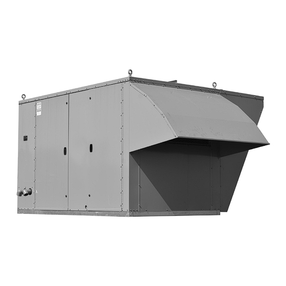
model mPr commercial Packaged ventilation
system unit (c-cabinet size shown)
WARNING
Improper installation, adjustment, alteration,
service or maintenance can cause property
damage, injury or death, and could cause
exposure to substances which have been
determined by various state agencies to cause
cancer, birth defects or other reproductive
harm. Read the installation, operating and
maintenance instructions thoroughly before
installing or servicing this equipment.
WARNING
This unit contains R-410A high pressure
refrigerant. Hazards exist that could result in
personal injury or death. Installation,
maintenance, and service must only be
performed by an HVAC technician qualified in
R-410A refrigerant and using proper tools and
equipment. Due to much higher pressure of
R-410A refrigerant, DO NOT USE service
equipment or tools designed for refrigerants
other than R410A.
PLEASE BE SURE TO LEAVE IT WITH THE OWNER WHEN YOU LEAVE THE JOB.
installation and service manual
commercial packaged ventilation system units
model mPr
THIS MANUAL IS THE PROPERTY OF THE OWNER.
MCP15-500.7
(for units with 24 digit model numbers)
WARNING
Fire or eXPlosion HaZard
Failure to follow safety warnings exactly could
result in serious injury, death or property
damage.
Be sure to read and understand the installation,
operation and service instructions in this manual.
Improper installation, adjustment, alteration,
service or maintenance can cause serious
injury, death or property damage.
Do not store or use gasoline or other
flammable vapors and liquids in the vicinity
of this or any other appliance.
WHat to do iF You smell Gas:
• Do not try to light any appliance.
• Do not touch any electrical switch, do
not use any phone in your building.
• Leave the building immediately.
• Immediately call your gas supplier from
a phone remote from the building.
Follow the gas supplier's instructions.
• If you cannot reach your gas supplier,
call the fire department.
Installation and service must be performed by
a qualified installer, service agency or the gas
supplier.
inspection on arrival
1. Inspect unit upon arrival. In case of damage, report it
immediately to transportation company and your local
factory sales representative.
2. Check rating plate on unit to verify that power supply meets
available electric power at the point of installation.
3. Inspect unit upon arrival for conformance with description
of product ordered (including specifications where
applicable).
MCP15-500.7
5H0816400000
March, 2018
1
Advertisement
Table of Contents
Troubleshooting

Related Manuals for Modine Manufacturing MPR


Summary of Contents for Modine Manufacturing MPR
-
Page 1: Inspection On Arrival
(for units with 24 digit model numbers) model mPr commercial Packaged ventilation system unit (c-cabinet size shown) WARNING Fire or eXPlosion HaZard Failure to follow safety warnings exactly could result in serious injury, death or property damage. -
Page 2: Special Precautions
Section comes from a single point power connection on which, if not avoided, COULD result in death or serious injury. the unit. Disconnect power supply at model MPR before 3. caution: Indicates a potentially hazardous situation making wiring connections to prevent electrical shock which, if not avoided, MAY result in minor or moderate injury. -
Page 3: Table Of Contents
Model Nomenclature ............57-59 special design requests Commercial Warranty ...........Back Page Modine Manufacturing Company will sometimes build units with special features as requested by the customer. This manual only covers standard features and does not include any changes made for special feature requests by the customer. -
Page 4: Unit Location
All dimensions are +1/8 inch. When locating the packaged rooftop unit, Model MPR, When a roof curb is used in conjunction with factory consider general space and cooling/heating requirements and supplied discharge and/or return air connectors, the availability of gas and electrical supply. - Page 5 clearances / rooF curb installation Figure 5.1 - Combustible Material & Service Clearances B- AND C-CABINET UNITS WITHOUT ENERGY RECOVERY D-CABINET UNITS WITHOUT ENERGY RECOVERY FIELD INSTALLED ACCESSORY 36.0 SEE NOTE 2 SEE NOTE 2 36.0 RAINHOOD SEE NOTE 4 48.0 SEE NOTE 3 36.0...
-
Page 6: General Rigging Instructions/Unit Installation
• B-Cabinet sized units without Energy Recovery include Figure 6.1 - Typical Rigging for Model MPR (4) eye bolts at each corner on the top of the unit. B-CABINET UNIT - NO ENERGY RECOVERY • B-Cabinet sized units with Energy Recovery include (6) - Page 7 duct installation and utilitY connections duct installation 1. The unit is designed to accept 90° flanged ductwork on both the supply and return air openings. Refer to the roof curb or the unit base dimensional drawings to determine the location of the openings.
-
Page 8: Duct & Condensate Drain Installation
condensate drain installation evap condensate drain trap installation Figure 8.2 - Condensate Drain Trap Installation IMPoRtANt note: All piping components shown are supplied by others. TRAP HEIGHT (6" MINIMUM) A properly designed drain with trap must be installed immediately after the unit evaporator coil condensate drain CAPPED CLEANOUT pan connection. -
Page 9: Electrical Connections
electrical connections electrical connections WARNING For field wiring to the factory terminal strip, the terminal strip connections are designed to clamp down on the wires. roltage. To properly connect the wires to the terminal strip: Disconnect power supply before making wiring • Push a small flat-head screwdriver into the square hole on connections or working on this equipment. -
Page 10: Gas Connections
If the unit is a C-Cabinet sized unit with a Modine supplied Gas connections Energy Recovery Module, Model ERM, the wiring connection between the MPR unit and the ERM unit must WARNING be made by extending the loose end of the wire drop roltage. - Page 11 Gas connections Table 11.1 - Natural Gas Heating Gas Consumption 3. The gas piping to the unit can enter the unit from the side of the unit (refer to the unit dimensions) or from below (refer Furnace Size Gas Consumption Digit 6 Digit 18 to the base dimensions).
-
Page 12: Vent Terminals And Combustion Air Hoods
For units that require vent extension kits, refer Figure 12.1 - Power Exhauster Vent Terminal for to Literature #MCP15-574, “Installation Instructions, non-condensing Gas Furnace option Extended Vent Kit, Model MPR Gas Heat”. Table 12.1 - Power Exhauster Vent Terminal and combustion air Hood Quantity Note: Caulk mating... - Page 13 Gas HeatinG oPtion vent terminals and combustion air Hoods condensing Furnaces (b-cabinet) For C-Cabinet units with Condensing furnace types, as determined from Table 12.1 on page 12, refer to Figures 13.3 For B-Cabinet units with Condensing furnace types, as and 13.4 for vent termination installation details. The determined from Table 12.1 on page 12, refer to Figures 13.1 installation steps are as follows: and 13.2 for vent termination installation details.
-
Page 14: Gas Heating Option Condensate Drains & Traps
Gas HeatinG oPtion condensate drain and traP installation Figure 14.1 - Furnace Condensate Drain/Trap condensate drain and trap installation (condensing Furnace type only) system j For Condensing furnace types, as determined from Table 12.1 on page 12, during heating operation, condensate is produced in the furnace sections. -
Page 15: Hot Water Piping Connections
Hot Water PiPinG connections • O n 3-way valve control configurations, include a balancing revieW beFore ProceedinG valve between the supply line and control valve to balance the system. tHis section aPPlies to units WitH • I nclude a hose bib drain valve on the bottom of the supply manifold to allow for periodic flushing of the system to oPtional Hot Water Heat remove sediments from the coil. -
Page 16: Start-Up Procedure
Modine supplied Energy Recovery Module, Model ERM, The junction box must not be disassembled unless verify that the wiring connection between the MPR unit and the main power supply from the building to the unit is the ERM unit has been properly installed. If the unit is a de-energized. -
Page 17: Blower Adjustments
start-uP Procedure - continued 17. Check that the evaporator drain pan drain trap has been 26. For units equipped for dual power supply sources, the unit primed with water. should be started separately on the main power feed and again on the auxiliary power feed to verify proper unit and 18. - Page 18 start-uP Procedure - continued blower adjustments – direct drive Fans Figure 18.1 - Direct Drive Blower Example All direct drive supply fan speed adjustments can be performed with the Modine Control System programmable microprocessor controller. There are two ways to access the menus: Using the user interface on the main unit controller.
-
Page 19: Airflow Proving Switch And Dirty Filter Switch
start-uP Procedure - continued blower adjustments – belt drive Fans air Flow Proving switch / optional dirty Filter switch All belt drive supply fan and, if applicable, exhaust fan speed The air flow proving switch is factory installed in the blower adjustments can be made with the adjustable sheave on the compartment. -
Page 20: Checking Refrigerant Charge
start-uP Procedure - continued checking refrigerant charge WARNING c. Subtract the saturated temperature from the measured suction line temperature to determine the evaporator superheat. The superheat should be 8-12°F. Determine if the system is undercharged or overcharged This unit contains R-410A high pressure refrigerant. and correct as follows: Hazards exist that could result in personal injury or death. -
Page 21: Gas Heating Option
(model valve instruction sheet for location.) MPR) serial plate. 8. Check to ensure that gas controls sequence properly (see Digit 11 of the furnace model number denotes the type of gas Controls Manual). - Page 22 start-uP Procedure - continued or adjust the high fire manifold pressure to be 3.5" W.C. Error Codes” section in the next column to clear the errors. If the pressure needs to be adjusted, press or hold 10. For furnace models with Digit 11=6 or 8, verify the furnace Button #1 to increase gas flow and press or hold Button control board and modulating valve is communicating #2 to decrease gas flow.
- Page 23 start-uP Procedure - continued Figure 23.3 - Furnace Master/Slave Locations by pressing the UP or DOWN buttons. Codes will be displayed followed by the number of days since the fault was detected. 3. To clear the fault codes from memory, press the DOWN button until “CLr”...
- Page 24 start-uP Procedure - continued Figure 24.1 - Gas Heat Option Gas controls - b-cabinet sized units 1 Power exhauster 5 Solid state ignition control board 12 Condensate drain float switch (94% efficiency furnace only) 2 Maxitrol EXA STAR modulating 6 Furnace control board 13 Compartment strip heater/thermostat gas valve 7 Vent differential pressure proving switch...
- Page 25 start-uP Procedure - continued Figure 25.1 - Gas Heat Option Gas controls - c-cabinet sized units left Furnace right Furnace (slave) (master) 1 Power exhauster 8 Not Applicable 2 Maxitrol EXA STAR modulating 9 Vent differential pressure proving switch gas valve (right-hand furnace only) 10 Direct spark ignitor 3 Main combination gas valve 11 Manifold tee pressure tap...
- Page 26 start-uP Procedure - continued Figure 26.1 - Gas Heat Option Gas Controls - D-Cabinet Sized Units - 800,000 Btu/hr and Smaller (81% Eff) 1 Power exhauster 7 Vent differential pressure proving switch 2 Maxitrol EXA STAR modulating gas valve 8 Direct spark ignitor 3 Main combination gas valve 9 Manifold pressure tap on manifold tee 4 High limit control (hidden behind piping as shown)
- Page 27 start-uP Procedure - continued Figure 27.1 - Gas Heat Option Gas Controls - D-Cabinet Sized Units - 900,000 Btu/hr and Larger (81% Eff) Slave Furnace “B” k Master Furnace k Refer to Figure 23.3 for location of furnace positions. Refer to Figure 26.1 for idenfication of furnace components.
-
Page 28: Energy Recovery Option (B-Cabinet Units Only)
Section comes from a single point power connection bearings are permanently lubricated as well, except for on the unit. Disconnect power supply at model MPR pillow block bearings or those identified with grease fittings. before making wiring connections to prevent electrical For motors or blower bearings that are not permanently shock and equipment damage. - Page 29 unit comPonent identiFication / location Figure 29.1 - Controls Cabinet - Energy Recovery Section (B-Cabinet only, if equipped) j 15 (S) Outside air filters 2 (S) Controls compartment with side wiring entrance 16 (O) Outside air filters pressure drop switch 3 (S) Power distribution block 17 (S) Blower door switch 4 (S) Carel pCOxs microprocessor controller...
-
Page 30: Unit Features/Options Location Drawings
unit comPonent identiFication / location all FiGures on tHis PaGe are For b- and c-cabinet siZed units Figure 30.1 - Blower/Evaporator/Filter/Damper Sections j Figure 30.2 - Condenser Section j 20 21 1 (O) GFCI convenience outlet (not shown here, refer to Figure 24.1) 1 (S) Condenser fan housing 2 (S) Blower door switch 2 (S) Condenser fan motors... - Page 31 unit comPonent identiFication / location all FiGures on tHis PaGe are For d-cabinet siZed units Figure 31.1 - Compressor/Condenser/Blower/Evaporator/Filter/Damper Sections j (S) Blower door switch 17. (O) Return air damper (S) Airflow proving switch (not shown, located on opposite side) 18.
- Page 32 unit comPonent identiFication / location Figure 32.1 - controls cabinet - b-cabinet sized units j 18 22 23 27 28 19 (O) Power exhaust fan contactor/variable frequency drive 1 Not applicable circuit breaker 2 (S) Condenser fan motor circuit breakers 20 (S) Main controls step-down transformer primary circuit 3 (O) Hot gas reheat circuit shut-off valves breaker...
- Page 33 unit comPonent identiFication / location Figure 33.1 - controls cabinet - c-cabinet sized units j For units where unit serial number digit 12=2 (carel evd superheat controller) 20 21 1 (S) High voltage power distribution block 19 (O) Power exhaust fan contactor/variable frequency drive circuit breaker 2 (S) Condenser fan motor circuit breakers (qty.
- Page 34 unit comPonent identiFication / location Figure 34.1 - controls cabinet - d-cabinet sized units j (O) Remote shutdown relay (CR1) (O) Supply fan enable relay (CR4) [for units with two supply fan VFD’s] (S) Carel EVD Ultracap - Circuit #1 (S) Carel EVD Ultracap - Circuit #2 (S) Low voltage terminal strip (S) Controls secondary circuit breaker (CB5)
- Page 35 unit comPonent identiFication / location Figure 35.1 - Power cabinet - d-cabinet sized units j 26 27 (O) Gas Heat Control Transformer Secondary Circuit Breaker 14. (O) Main Factory Mounted Disconnect Switch (O) Wiring Terminals for Item #1 15. (S) Supply Fan Power Distribution Block (dual blower 1-10HP) (O) Phase Monitor Relay 16.
-
Page 36: Dimensions/Weights
dimensions - b-cabinet siZe unit (no enerGY recoverY) Figure 36.1 - Unit Dimensions (inches) CONDENSING SECTION FAN QUANTITY: (2) FOR 7 AND 10 TON UNITS (3) FOR 13 , 15, AND 20 TON UNITS (4) 1.5" LIFTING EYE BOLTS (EACH CORNER OF UNIT) 55.90 ACCESSORY RAINHOOD AND BIRDSCREEN... - Page 37 dimensions - b-cabinet unit base/rooF curb (no enerGY recoverY) Figure 37.1 - Unit Base Dimensions (inches) 100.00 95.22 UNIT ACCESS SIDE 2.39 5.72 9.76 10.73 2.00" DIA. GAS FURNACE PIPING HOLE (IF EQUIPPED) 2.39 10.50 2.39 1.75" DIA. RETURN/ FURNACE CONDENSATE 5.50 EXHAUST DRAIN LINE HOLE...
-
Page 38: B-Cabinet Size Unit With Energy Recovery
dimensions - b-cabinet siZe unit (WitH enerGY recoverY) Figure 38.1 - Unit Dimensions (inches) CONDENSING SECTION ENERGY RECOVERY ENERGY RECOVERY FAN QUANTITY: WHEEL ECONOMIZER EXHAUST AIR (2) FOR 7 AND 10 TON UNITS BYPASS DAMPER RAINHOOD (3) FOR 13, 15, AND 20 TON UNITS (4) 1"... - Page 39 dimensions - b-cabinet unit base/rooF curb (W/ enerGY recoverY) Figure 39.2 - Unit Base Dimensions (inches) 176.00 172.50 102.25 168.00 UNIT ACCESS SIDE 2.39 163.22 9.76 2.00" DIA. 10.73 GAS FURNACE 5.72 PIPING HOLE (IF EQUIPPED) 2.39 10.50 2.39 1.75" DIA. FURNACE 5.50 RETURN/...
-
Page 40: C-Cabinet Size Unit
dimensions - c-cabinet siZe unit Figure 40.1 - Unit Dimensions (inches) CONDENSING SECTION FAN QUANTITY: (2) FANS FOR 15 TON UNIT (3) FANS FOR 20 THRU 30 TON UNITS (4) 1.50" LIFTING EYE BOLTS (EACH CORNER OF UNIT) 65.92 60.11 107.12 ACCESSORY RAINHOOD AND BIRDSCREEN... - Page 41 dimensions - c-cabinet siZe unit base / rooF curb Figure 41.1 - Unit Base Dimensions (inches) 2.00" DIA. UNIT ACCESS 2.00" DIA. ELECTRICAL POWER SIDE ELECTRICAL POWER BOTTOM PIPING HOLES BOTTOM PIPING HOLES HOT WATER 106.22 2.53 PIPING ENTRANCE (UNITS WITH HOT 2.53 WATER HEAT ONLY) 9.24...
-
Page 42: D-Cabinet Size Unit
dimensions - d-cabinet siZe unit Figure 42.1 - Unit Dimensions (inches) 103.07 CONDENSING SECTION FAN QUANTITY: (4) FANS FOR 30 AND 40 TON UNIT (6) FANS FOR 52 AND 60 TON UNITS ACCESSORY RAINHOOD AND BIRDSCREEN (FIELD INSTALLED ACCESSORY) 180.63 40.36 CONDENSING SECTION... - Page 43 dimensions - d-cabinet siZe unit base / rooF curb Figure 43.1 - Unit Base Dimensions (inches) 180.00 172.00 4.00 4.00 18.26 8.52 RETURN AIR SUPPLY AIR OPENING 92.75 100.75 OPENING (IF 60.12 4.00 SELECTED) 14.38 25.00 4.39 21.89 34.24 3.52 LOW VOLT CONTROL PANEL ON THIS SIDE BASE ASSEMBLY AS...
-
Page 44: Base Model Weights
base model WeiGHts Table 44.1 - Approximate Base Model Weight - (lbs.) cabinet size cabinet size section description section description MPR07 2377 20kW MPR10 2489 40kW MPR13 2570 60kW MPR15 2585 2710 80kW Electric MPR20 2685 2894 100kW Base Unit MPR26 2898 120kW... -
Page 45: Option And Accessory Pressure Drop Tables
oPtion and accessorY Pressure droP tables Table 45.1 - Pressure Drop Data - B-Cabinet Sized Unit Supply Fan j Feature 7 & 10 Ton 0.06 0.08 0.10 0.13 0.16 0.19 0.22 0.25 0.28 0.31 0.35 0.38 0.42 0.46 0.50 0.54 0.58 0.62 0.67 0.71 0.76 Evaporator Coil 13, 15, &... - Page 46 oPtion and accessorY Pressure droP tables Table 46.1 - Pressure Drop Data - C-Cabinet Sized Unit Supply Fan jk Feature Evaporator Coil 0.11 0.13 0.15 0.16 0.18 0.20 0.21 0.23 0.25 0.27 0.29 0.32 0.36 0.40 0.44 0.49 0.53 0.58 0.62 0.67 0.87 Hot Gas Reheat Coil 0.05 0.05 0.05 0.05 0.05 0.05 0.05 0.05 0.05 0.05 0.05 0.06 0.06 0.07 0.08 0.08 0.09 0.10 0.11 0.13 0.18 MERV 10...
-
Page 47: Option And Accessory Pressure Drop Tables
oPtion and accessorY Pressure droP tables Table 47.1 - Pressure Drop Data - D-Cabinet Sized Unit Supply Fan jk Feature 30 & 40 Ton 0.17 0.24 0.32 0.41 0.51 0.62 0.73 0.86 0.99 Evaporator Coil 52 & 60 Ton Future Future Future Future Future Future Future Future Future Future Future Future 30 &... -
Page 48: Maintenance
maintenance WARNING that the unit has been wired according to the wiring diagram. Check that fuses or circuit breakers are in place and When the dead front disconnect switch(es) (for main unit sized correctly. and/or powered convenience outlet option) is in the “OFF”... - Page 49 maintenance - continued cooling coil drain Pan and drain system 3. The heat exchanger should be checked annually for cracks. If a crack is detected, the heat exchanger should be The drain pan, trap, and drain pipe must be cleaned regularly to replaced before the unit is put back into service.
-
Page 50: Maintenance
maintenance - continued Hot Water Heat coil maintenance energy recovery exhaust assembly If the unit is equipped with a Modine supplied Energy Recovery If the unit is supplied with a factory installed hot water heat coil, Exhaust section, check the following: check the following: The energy recovery wheel drive belt is subject to natural Periodically, inspect the coils for signs of corrosion and... -
Page 51: Service & Troubleshooting
When servicing or repairing this equipment, use only factory- qualified service agency. approved service replacement parts which may be obtained by contacting Modine Manufacturing Company. Refer to To check most of the Possible Remedies in the troubleshooting the rating plate on the unit for complete unit model number, serial number, and company address. - Page 52 SERVICE & TROUBLESHOOTING - CONTINUED Table 52.1 - Troubleshooting (Continued) trouble Possible cause Possible remedy 1. See Problems “A” and “B” 1. See Problems “A” and “B” F. Compressor(s) Do Not Operate 2. Controls are in Unoccupied mode 2. Wait for Occupied mode or override 3.
- Page 53 PAGE INTENTIONALLY LEFT BLANK MCP15-500.7...
- Page 54 SERVICE & TROUBLESHOOTING - CONTINUED table 54.1 - Furnace Master Control Board (VB1200) Error Codes (Applies to B-, C-, and D-Cabinet Units with Gas Heat Option furnace model number Digit 11=6 or 8) j display code description additional comments and notes Board Failure (Up to 10 sec @ power up) Verify 24 VAC signal input at connector J6.
-
Page 55: Service & Troubleshooting
SERVICE & TROUBLESHOOTING - CONTINUED Table 55.1 - Furnace Slave Control Board (VB1201) Error Codes (Applies only to C- and D-Cabinet Units with Gas Heat Option furnace model number Digit 11=8) j color Flashes condition error conditions No power to the control board Steady On Hard lockout on control fault or no 24 VAC. -
Page 56: Serial Plates
MODEL IDENTIFICATION & serial Plates/numbers model identification Depending on options included, the unit may have more than one Serial Plate. Figure 56.1 shows the Serial Plate for the main unit, while Figure 56.2 shows the Serial Plate for the gas heat option. When servicing, repairing or replacing parts on these units, locate the model Serial Plate of the unit and always give the complete Model Number and Serial Number of the unit. -
Page 57: Model Nomenclature
Table 57.1 shows the nomenclature for the gas heat section option. • Tables 58.1 and 59.1 on the following pages show the nomenclature for the main unit. Table 57.1 - Model Nomenclature - Gas Furnace Option for Model MPR cabinet digits... - Page 58 - model mPr Table 58.1 - Model Nomenclature - Main Unit cabinet digits indicates description value 1, 2, 3 Unit Type Commercial Packaged Ventilation Unit ● ● ● 7, 10, or 13 ton 07, 10, 13 ● 15 or 20 ton 15, 20 ●...
-
Page 59: Model Nomenclature
C through L include a Motor Starter, Q through Y include a Variable Frequency Drive (VFD). m MPR C-Cabinet units that interface to energy recovery exhaust will always be "N". The Wheel Diameter, Exhaust Blower Configuration, Exhaust Blower Motor HP, and Energy Wheel Preheat is called out in the ERM model nomenclature, when applicable, on C-Cabinet sized units. All D-Cabinet units are “N”. -
Page 60: Commercial Warranty
High Intensity Infrared Units sheet metal Parts All Products As Modine Manufacturing Company has a continuous product improvement program, it reserves the right to change design and specifications without notice. modine manufacturing company 1500 DeKoven Avenue Racine, WI 53403 Phone: 1.800.828.4328 (HEAT)
Need help?
Do you have a question about the MPR and is the answer not in the manual?
Questions and answers