Table of Contents
Advertisement
WARNING
1. Improper installation, adjustment, alteration,
service or maintenance can cause property
damage, injury or death, and could cause
exposure to substances which have been
determined by various state agencies to cause
cancer, birth defects or other reproductive
harm. Read the installation, operating and
maintenance instructions thoroughly before
installing or servicing this equipment.
2. Units with DX evaporator coils (refer to
model nomenclature) contain R-410A high
pressure refrigerant. Hazards exist that could
result in personal injury or death. Installation,
maintenance, and service must only be
performed by an HVAC technician qualified
in R-410A refrigerant and using proper tools
and equipment. Due to much higher pressure
of R-410A refrigerant, DO NOT USE service
equipment or tools designed for refrigerants
other than R410A.
AVERTISSEMENT
1. Une installation, un réglage, une altération, une
réparation ou une maintenance impropre risque
de causer des dommages, des blessures ou
la mort, et d'engendrer une exposition à des
substances dont certains États ont déterminé
qu'elles étaient cancérogènes ou pouvaient
causer des malformations à la naissance et
des problèmes de reproduction. Lisez bien
les instructions d'installation, d'utilisation et de
maintenance avant d'installer ou de réparer cet
appareil.
PLEASE BE SURE TO LEAVE IT WITH THE OWNER WHEN YOU LEAVE THE JOB.
INSTALLATION AND SERVICE MANUAL
THIS MANUAL IS THE PROPERTY OF THE OWNER.
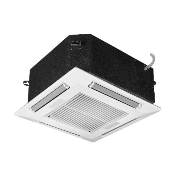
Ductless Split Ceiling Cassette
Models SSD, SSH and SCW
Models CSD, CSH and CCW
AVERTISSEMENT
2. Les unités munies de serpentins évaporateurs
DX (reportez-vous à la nomenclature du
modèle) contiennent du fluide frigorigène à
haute pression R-410A. Des dangers existent
qui, s'ils se matérialisent, pourraient entraîner
des blessures ou la mort. L'installation,
l'entretien et le service ne doivent être effectués
que par un technicien de CVC qualifié quant à
l'usage du fluide frigorigène R-410A en utilisant
les outils et l'équipement appropriés. En raison
de la pression beaucoup plus élevée du fluide
frigorigène R-410A, N'utilisez PAS des outils
ou de l'équipement de service qui ne sont pas
conçus spécifiquement pour le R-410A.
IMPORTANT
1. The use of this manual is specifically intended
for a qualified installation and service agency. A
qualified installation and service agency must
perform all installation and service of these
appliances.
2. Units with DX evaporator coils (refer to model
nomenclature) contain the refrigerant R-410A.
Review the R-410A Material Safety Data Sheet
(MSDS) for hazards and first aid measures.
IMPORTANT
1. Ce manuel est spécifiquement destiné
au personnel d'une entreprise qualifiée
d'installation et d'entretien. Toutes les
opérations d'installation et d'entretien doivent
être confiées à une entreprise qualifiée.
2. Les unités munies de serpentins évaporateurs
DX (reportez-vous à la nomenclature du
modèle) contiennent du fluide frigorigène
R-410A. Pour les dangers et les mesures de
premiers soins, consultez la fiche signalétique
du R-410A.
8-504.11
5H1015480001
December, 2023
Advertisement
Table of Contents

Related Manuals for Modine Manufacturing SSD


Summary of Contents for Modine Manufacturing SSD
- Page 1 8-504.11 5H1015480001 December, 2023 INSTALLATION AND SERVICE MANUAL Ductless Split Ceiling Cassette Models SSD, SSH and SCW Models CSD, CSH and CCW AVERTISSEMENT 2. Les unités munies de serpentins évaporateurs DX (reportez-vous à la nomenclature du modèle) contiennent du fluide frigorigène à...
-
Page 2: Table Of Contents
TABLE OF CONTENTS IMPORTANT Special Precautions .............3 Hazard Intensity Levels ............3 1. Refrigerant charging should only be carried out Special Design Requests .............5 by an EPA-certified air conditioning contractor. Unit Location ................6 2. This appliance is not intended to be operated Unpacking ................6 or serviced by persons (including children) with... -
Page 3: Special Precautions
SPECIAL PRECAUTIONS SPECIAL PRECAUTIONS DANGER THE INSTALLATION AND MAINTENANCE INSTRUCTIONS IN THIS MANUAL MUST BE FOLLOWED TO PROVIDE Appliances must not be installed where they may be exposed SAFE, EFFICIENT, AND TROUBLE-FREE OPERATION. IN to potentially explosive or flammable atmosphere. ADDITION, PARTICULAR CARE MUST BE EXERCISED REGARDING THE SPECIAL PRECAUTIONS LISTED BELOW. - Page 4 SPECIAL PRECAUTIONS IMPORT ANT CAUTION 1. Unit Performance will be significantly reduced at or above 1. Do not overcharge the refrigeration system. This can lead 7215 ft (2200 m) and should not be operated above this to elevated compressor discharge pressure and possibly altitude.
-
Page 5: Special Design Requests
SPECIAL PRECAUTIONS IMPORT ANT 1. La performance de l’unité sera grandement réduite à une altitude de 7215 pieds (2200 m) et elle ne doit pas être utilisée au-delà de cette hauteur. 2. Pour les unités installées au plafond, vérifiez que le plafond peut soutenir le poids de l’unité. -
Page 6: Unit Location
UNIT LOCATION For units with supplementary electric heat (Digit 9 = A), the UNIT LOCATION minimum clearance from the unit to combustible surfaces is DANGER 0 in (0cm). The unit must be installed square and level. The condensate drain should have downward slope (1 Appliances must not be installed where they may be exposed in per 100 in (2.54 cm per 254 cm)) in a horizontal run to potentially explosive or flammable atmosphere. -
Page 7: Positioning Wall Mounted Thermostat
UNIT LOCATION Positioning Wall Mounted Thermostat For proper temperature control, the thermostat should be mounted as follows: Position the thermostat approximately 48 in (122 cm) above floor level. Do not position thermostat where it can be directly affected by the unit’s discharge air stream. Avoid external walls and drafts from windows and doors. -
Page 8: Installation
INSTALLATION Installation Installation Guide An installation guide is included in the Owner Information packet IMPORTANT provided with the unit. The installation guide sets the proper height between the chassis and ceiling. Prepare the installation guide by folding the flat metal piece, by hand, along the For ceiling mounted units, check that the ceiling is capable of perforations as shown in Figure 8.2. -
Page 9: Condensate Piping
INSTALLATION Figure 9.1 - Threaded Rod Dimension Duct Collars Supply air branch duct and outside air duct collars can be attached to the unit chassis by following the below steps: 3/8 in Supply Air Duct Collars: Up to two supply air ducts can be attached per unit. Place the polystyrene blanking strip in the fascia supply air opening on the same side where the supply duct collar is to Threaded Rod... -
Page 10: Piping Installation
INSTALLATION Piping Installation Piping Installation – Hot/Chilled Water Coils Piping Installation – DX and Heat Pump Units CAUTION CAUTION 1. Units not approved for use in potable water systems. 2. Hot water supplied to the hot water heating option must not Do not overcharge the refrigeration system. -
Page 11: Wiring
INSTALLATION Figure 11.1 - CAUTION Hot/Chilled Water Coil Piping Installation 1. Ensure that the supply voltage to the appliance, as AIR VENT indicated on the serial plate, is not 5% less than the rated voltage. SHUT-OFF UNION STRAINER VALVE 2. In order to avoid a hazard due to inadvertent resetting of SUPPLY the thermal cut-out, this appliance must not be supplied through an external switching device, such as a timer, or... -
Page 12: Disconnect Switch
INSTALLATION Disconnect Switch wiring diagram by the "read the instructions" symbol For models with a factory installed disconnect switch (Digit 12 = See wiring diagram for specifics. D), the switch will be installed on the side of the control panel. See Figure 20.1, Figure 21.1, Figure 22.1, Figure 23.1 and Fascia Assembly Figure 24.1 for the location of the control panel on the unit. -
Page 13: Start-Up Procedure
START-UP PROCEDURE Start-Up Procedure 7-8 ounces (198 - 227 grams) of water down the pump outlet, switch the unit on, select cooling mode and the IMPORTANT lowest possible temperature set point then observe the water being pumped from the unit. Where fitted, check the operation of the hot water valve Start up and adjustment procedures, installation, and service or the electrical heat elements by switching the system... -
Page 14: Start Up Sheet - Example
START UP SHEET - EXAMPLE Figure 14.1 - Start Up Sheet – Page 1 – EXAMPLE CASSETTE START UP SHEET 8-504.11... - Page 15 START UP SHEET - EXAMPLE Figure 15.1 - Start Up Sheet – EXAMPLE – Page 2 8-504.11...
-
Page 16: Sequence Of Operation
SEQUENCE OF OPERATION SEQUENCE OF OPERATION Setting Jumper Links Jumper Links are located on the Microprocessor Controller PCB DIGIT 8=E: ELECTRO-MECHANICAL CONTROLS to offer different control features and their functionality is listed A 24V signal from the thermostat to terminal G supplies power below in Table 16.1. - Page 17 THIS PAGE INTENTIONALLY LEFT BLANK 8-504.11...
-
Page 18: Micro-Processor Operation
MICRO-PROCESSOR OPERATION Micro-Processor Controls Operation Press the ON/SEND button to send information to the cassette unit. Receiver Modes The IR receiver is an extension of the control board and is Press the MODE button to switch between: located on the fascia of the unit, connected by means of a 7-pin plug and socket. - Page 19 MICRO-PROCESSOR OPERATION Transmitter (continued) Press the SELECT button again - minutes will flash. Adjust the minutes using the (+) or (-) buttons. Temperature Set-Point Adjust the desired temperature using the (+) or (-) buttons. STOP TIME: Press the SELECT button twice - PROGRAM & STOP (flashing) Press the ON/SEND button to send information to the cassette will appear on display.
-
Page 20: Dimensions
DIMENSIONS Small Chassis: Chilled Water Units Figure 20.1 - Dimensions – Small Chassis: Chilled Water Units – Size 08 and 12 1. Dimensions shown are inches (mm) 8-504.11... -
Page 21: Medium Chassis: Chilled Water Units
DIMENSIONS Medium Chassis: Chilled Water Units Figure 21.1 - Dimensions – Medium Chassis: Chilled Water Units – Size 18 and 20 1. Dimensions shown are inches (mm) 8-504.11... -
Page 22: Large Chassis: Chilled Water Units
DIMENSIONS Large Chassis: Chilled Water Units Figure 22.1 - Dimensions – Large Chassis: Chilled Water Units – Size 33 and 36 1. Dimensions shown are inches (mm) 8-504.11... -
Page 23: Medium Chassis: Dx And Heat Pump Units
DIMENSIONS Medium Chassis: DX and Heat Pump units Figure 23.1 - Dimensions – Medium Chassis: DX and Heat Pump units – Size 18 and 24 1. Dimensions shown are inches (mm) 8-504.11... -
Page 24: Large Chassis: Dx And Heat Pump Units
DIMENSIONS Large Chassis: DX and Heat Pump units Figure 24.1 - Dimensions – Large Chassis: DX and Heat Pump units – Size 30, 36, and 42 1. Dimensions shown are inches (mm) 8-504.11... - Page 25 THIS PAGE INTENTIONALLY LEFT BLANK 8-504.11...
-
Page 26: Dx Cooling Only And Heat Pump Units - Ip Units
TECHNICAL DATA DX Cooling Only and Heat Pump Units - IP Units Table 26.1 - Technical Data – DX Cooling Only and Heat Pump Units - IP Units Model Digit 2,3 + Model Size DESCRIPTION UNITS SD/SH 18 SD/SH 24 SD/SH 30 SD/SH 36 SD/SH 42... -
Page 27: Dx Cooling Only And Heat Pump Units - Si Units
TECHNICAL DATA DX Cooling Only and Heat Pump Units - SI Units Table 27.1 - Technical Data - DX Cooling Only and Heat Pump Units - SI Units Model Digit 2,3 + Model Size DESCRIPTION UNITS SD/SH 18 SD/SH 24 SD/SH 30 SD/SH 36 SD/SH 42... -
Page 28: Chilled Water Units - Ip Units
TECHNICAL DATA Chilled Water Units - IP Units Table 28.1 - Technical Data – Chilled Water Units - IP Units Model Digit 2,3 + Model Size DESCRIPTION UNITS CW08 CW12 CW18 CW20 CW33 CW36 w/ Standard Filters (1) BTU/hr 7,800 11,200 18,200 18,600... -
Page 29: Chilled Water Units - Si Units
TECHNICAL DATA Chilled Water Units - SI Units Table 29.1 - Technical Data - Chilled Water Units - SI Units Model Digit 2,3 + Model Size DESCRIPTION UNITS CW08 CW12 CW18 CW20 CW33 CW36 w/ Standard Filters (1) 10.1 COOLING CAPACITY w/ MERV 10 Filters (2) Material: Fascia... -
Page 30: Exploded Unit Drawing & Parts List - Chilled Water
EXPLODED UNIT DRAWING & PARTS LIST – CHILLED WATER Figure 30.1 - Exploded Unit Drawing & Parts List – Chilled Water – Sizes 08 and 12 Handset Lorem ipsum Lorem ipsum Air Deflector Vanes (4) Cassette Chassis Freeze Protection Thermostat Chilled Water Coil Filter Electric Heater Element Assembly... -
Page 31: Exploded Unit Drawing & Parts List - Dx & Heat Pump
EXPLODED UNIT DRAWING & PARTS LIST – DX & HEAT PUMP Figure 31.1 - Exploded Unit Drawing & Parts List – DX and Heat Pump – Sizes 18 through 42 Cassette Chassis Vane Evaporator Coil Vane Motor Assembly Condensate Tray Filter Condensate Tray Support Fascia... -
Page 32: Maintenance
MAINTENANCE MAINTENANCE – INDOOR UNIT IMPORTANT WARNING 1. Start up and adjustment procedures, installation, and service of these appliances must be performed by a 1. Disconnect power supply before making wiring connections qualified installation and service agency. or working on this equipment. Follow all applicable safety 2. -
Page 33: Disassembly Procedure
MAINTENANCE Disassembly Procedure Replacement Parts Disconnect power supply before disassembly to prevent For ease of identification when ordering replacement parts or electrical shock and injury from moving parts. contacting the factory about your unit, please quote the unit type and unit serial number. This information can be found on the Fan Removal serial plate attached to your unit (see Figure 33.1). -
Page 34: Model Identification
MODEL IDENTIFICATION Table 34.1 - Model Number Designations 1 - Product Type (PT) 8 – Control Code (C) S or C - Cassette E – Electro-Mechanical Controls 2,3 - Unit Configuration (UC) M - Microprocessor Controls (Infrared Remote Control) SD – DX Cooling 9 –... -
Page 35: Troubleshooting
TROUBLESHOOTING WARNING ATTENTION 1. Disconnect power supply before making wiring connections 1. Ne tentez pas de réutiliser un composant mécanique ou or working on this equipment. Follow all applicable safety électrique qui a été mouillé. Ces composants doivent être procedures to prevent accidental power up. Failure to do remplacés. - Page 36 TROUBLESHOOTING Table 36.1 - Troubleshooting – Indoor Unit Trouble Possible Cause Possible Remedy A. Two LED Flashing 1. Faulty float switch. (Connected to micro terminals 1. See section "F. Condensate High Level (microprocessor ‘T4’) units: LED’s will flash)". (Microprocessor units only Digit 8 = M) 2.
- Page 37 TROUBLESHOOTING Troubleshooting – Indoor Unit (cont.) Trouble Possible Cause Possible Remedy D. No Cooling (cont.) 6. Check refrigerant charge by measuring operating 6. Indoor coil temperature too low. pressures. Check filters condition. (See page 32 for filter removal and cleaning instructions) 7.
- Page 38 TROUBLESHOOTING Tr oubleshooting – Indoor Unit (cont.) Trouble Possible Cause Possible Remedy H. No Heating (Hot 1. Incorrect MODE setting. (Microprocessor units 1. Check that the transmitter MODE is set to Heat or Auto only - Digit 8 = M) Mode.
- Page 39 THIS PAGE INTENTIONALLY LEFT BLANK 8-504.11...
- Page 40 As Modine Manufacturing Company has a continuous product improvement program, it reserves the right to change design and specifications without notice. Modine Manufacturing Company 1500 DeKoven Avenue Racine, WI 53403 Phone: 1.866.823.1631 www.modinehvac.com © Modine Manufacturing Company 2023...
Need help?
Do you have a question about the SSD and is the answer not in the manual?
Questions and answers