Advertisement
Quick Links
INSTALLATION AND SERVICE MANUAL SUPPLEMENT
GAS HEAT OPTION WITH FURNACE MODEL DIGIT 11=6, 9, A, B, C, OR D
These instructions apply only to the gas control options identified on page 3.
•
•
STOP
WARNING
Improper installation, adjustment, alteration,
service or maintenance can cause property
damage, injury or death, and could cause
exposure to substances which have been
determined by various state agencies to cause
cancer, birth defects or other reproductive
harm. Read the installation, operating and
maintenance instructions thoroughly before
installing or servicing this equipment.
PLEASE BE SURE TO LEAVE IT WITH THE OWNER WHEN YOU LEAVE THE JOB.
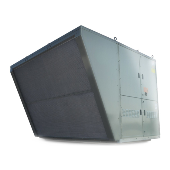
Packaged Ventilation/Dedicated Outside Air System (DOAS)
If the model MPR unit DOES NOT include the controls identified, these
instructions are not applicable and not to be used.
If the model MPR unit DOES include a gas heat option with control
identified as applicable on page 3, these instructions must be used in
conjunction with the Installation & Service Manual, Literature
#ATH15-500.10 that shipped with the unit. Read those instructions
thoroughly before installing or servicing this equipment.
THIS MANUAL IS THE PROPERTY OF THE OWNER.
ATH15-501.0 (Supplement to ATH15-500.10)
WARNING
FIRE OR EXPLOSION HAZARD
Failure to follow safety warnings exactly could
result in serious injury, death or property
damage.
Be sure to read and understand the installation,
operation and service instructions in this manual.
Improper installation, adjustment, alteration,
service or maintenance can cause serious
injury, death or property damage.
Do not store or use gasoline or other flammable
vapors and liquids in the vicinity of this or any
other appliance.
WHAT TO DO IF YOU SMELL GAS:
• Do not try to light any appliance.
• Do not touch any electrical switch, do not
use any phone in your building.
• Leave the building immediately.
• Immediately call your gas supplier from
a phone remote from the building.
Follow the gas supplier's instructions.
• If you cannot reach your gas supplier, call
the fire department.
Installation and service must be performed by a
qualified installer, service agency or the gas
supplier.
ATH15-501.0
5H0899700001
August, 2021
model MPR
1
Advertisement

Subscribe to Our Youtube Channel
Related Manuals for Modine Manufacturing Atherion MPR


Summary of Contents for Modine Manufacturing Atherion MPR
- Page 1 ATH15-501.0 5H0899700001 August, 2021 INSTALLATION AND SERVICE MANUAL SUPPLEMENT GAS HEAT OPTION WITH FURNACE MODEL DIGIT 11=6, 9, A, B, C, OR D Packaged Ventilation/Dedicated Outside Air System (DOAS) model MPR These instructions apply only to the gas control options identified on page 3. •...
-
Page 2: Special Precautions
SPECIAL PRECAUTIONS SPECIAL PRECAUTIONS WARNING THE INSTALLATION AND MAINTENANCE INSTRUCTIONS IN THIS MANUAL MUST BE FOLLOWED TO PROVIDE SAFE, EFFICIENT AND TROUBLE-FREE OPERATION. IN When servicing or repairing this equipment, use only ADDITION, PARTICULAR CARE MUST BE EXERCISED REGARDING THE SPECIAL PRECAUTIONS LISTED factory-approved service replacement parts. - Page 3 GAS HEAT OPTION MODEL IDENTIFICATION Digit 11 of the furnace model number denotes the type of gas REVIEW BEFORE PROCEEDING control used. These are defined below: THIS SECTION APPLIES TO ONLY CERTAIN For B-Cabinet (MPR Model Digit 6) Units Only: UNITS WITH OPTIONAL GAS HEAT The unit includes one heat exchanger with control as follows, (MPR MODEL DIGIT 17=2, 3, 5 OR 6).
- Page 4 GAS HEAT START-UP PROCEDURE Gas Heating Option Gas Pressure Setup Use the arrow buttons to find “Analog Outputs” with the title “Furnace 1 Signal” on the next line below. Press "Enter". 10. The cursor should go to the line “Manual Y4”. Use the The Gas Heating Option requires gas pressure be measured arrow buttons to set the value to “On”...
- Page 5 GAS HEAT START-UP PROCEDURE Figure 5.1 - Primary Furnace Control Board is needed, reset the “Manual Relay” and “Manual Position” to “Yes” to restart. 19. Furnace Digit 11=A or D Only (quad furnaces): For units with four furnace sections, furnace 1 is modulating. This furnace is controlled as described in 13 and 14 above.
- Page 6 GAS HEAT START-UP PROCEDURE Check to ensure that gas controls sequence properly (refer button #2 to the point where manifold pressure begins to be impacted. If the pressure at that point is less to the Controls Manual for additional information). than 3.3"...
-
Page 7: Final Check
GAS HEAT START-UP PROCEDURE Single and Two Stage Furnace / Manifold Section Figure 7.1 - Furnace Primary/Secondary Locations (applies to C- and D-Cabinet units only) The following steps are required to check/adjust the manifold pressure on the combination gas valve for staged furnaces (multiple furnace units only). - Page 8 FURNACE CONTROLLER ERROR CODES Furnace Controller Error Codes Tables 8.1 through 9.2 are for the furnace controllers on gas heat option furnace model digit 11= 6, 9, A, B, C, or D). Refer to the Troubleshooting section in the model MPR Installation and Service Manual, Literature ATH15-500.10 for a listing of Possible Causes and Remedies for the full unit.
-
Page 9: Error Codes
FURNACE CONTROLLER ERROR CODES Table 9.1 - Staged Furnace Control Boards (United Technologies Two Stage Control) Error Codes (Applies only to C- and D-Cabinet Units with Gas Heat Option furnace model number Digit 11=9 or C) Display Code Description Additional Notes Heartbeat Normal operation... - Page 10 GAS HEAT OPTION COMPONENT LOCATION Figure 10.1 - Gas Heat Option Gas Controls - B-Cabinet Sized Units 13. Compartment strip heater/thermostat Power exhauster Vent differential pressure proving switch (94% efficiency furnace only) Maxitrol EXA STAR modulating gas 14. Not applicable valve Direct spark ignitor Main combination gas valve...
- Page 11 GAS HEAT OPTION COMPONENT LOCATION Figure 11.1 - Gas Heat Option Gas Controls - C-Cabinet Sized Units Left Furnace Right Furnace (Secondary) (Primary) Left Furnace Right Furnace (Secondary) (Primary) (behind pipe) Power exhauster 10. Direct spark ignitor (behind control boards on 90% furnaces) Maxitrol EXA STAR modulating gas valve 11.
- Page 12 GAS HEAT OPTION COMPONENT LOCATION Figure 12.1 - Gas Heat Option Gas Controls - D-Cabinet Sized Units - 800,000 Btu/hr and Smaller (81% Eff) Power exhauster Vent differential pressure proving switch Maxitrol EXA STAR modulating gas valve (primary furnace only) Direct spark ignitor Main combination gas valve Manifold pressure tap on manifold tee (primary furnace only)
- Page 13 GAS HEAT OPTION COMPONENT LOCATION Figure 13.1 - Gas Heat Option Gas Controls - D-Cabinet Sized Units - 900,000 Btu/hr and Larger (81% Eff) Secondary Furnace “B” k Primary Furnace k Refer to Figure 7.1 for location of furnace positions. ...
- Page 14 GAS HEAT OPTION COMPONENT LOCATION Figure 14.1 - Gas Heat Option Gas Controls - D-Cabinet Units - 620,000 Btu/hr and Smaller (94% Eff) Power exhauster Direct spark ignitor Maxitrol EXA STAR modulating gas valve (primary furnace only) Manifold pressure tap on manifold tee (primary furnace only) 10.
- Page 15 GAS HEAT OPTION COMPONENT LOCATION Figure 15.1 - Gas Heat Option Gas Controls - D-Cabinet Units - 850,000 Btu/hr and Larger (Hybrid 87% Eff) Secondary Furnace “B” k Primary Furnace k Refer to Figure 7.1 for location of furnace positions. ...
- Page 16 As Modine Manufacturing Company has a continuous product improvement program, it reserves the right to change design and specifications without notice. Modine Manufacturing Company 1500 DeKoven Avenue Racine, WI 53403 Phone: 1.800.828.4328 (HEAT) www.modinehvac.com © Modine Manufacturing Company 2021...
Need help?
Do you have a question about the Atherion MPR and is the answer not in the manual?
Questions and answers