Kessel Aqualift S XL Instructions For Installation, Operation And Maintenance
Pumping station, wet installation, with one-handed closures
Hide thumbs
Also See for Aqualift S XL:
- Instructions for installation, operation and maintenance (208 pages) ,
- Manual (148 pages) ,
- Installation and operating manual (124 pages)
Table of Contents
Advertisement
Available languages
Available languages
Quick Links
ANLEITUNG FÜR EINBAU, BETRIEB UND WARTUNG
KESSEL Pumpstation Aqualift S XL
nasse Aufstellung (mit Einhandverschlüssen)
Installation
der Anlage wurde durchgeführt von Ihrem Fachbetrieb:
Name/Unterschrift
Stand 2019/12
Inbetriebnahme
Datum
Einweisung
Ort
Produktvorteile
Für fäkalienfreies
Abwasser
Großes Nutzvolumen
Einfache und schnelle
Montage
Geringes Gewicht
Hohe Sicherheit durch
Beständigkeit gegen
aggressive Medien
Grundwasserbeständig
bis 3m
Stempel Fachbetrieb
D
Seite 1
GB
Page 25
F
Page 49
I
Pagina 73
NL Pagina 97
PL Strona 121
Sach-Nr. 010-993
Advertisement
Chapters
Table of Contents

Related Manuals for Kessel Aqualift S XL


Summary of Contents for Kessel Aqualift S XL
- Page 1 ANLEITUNG FÜR EINBAU, BETRIEB UND WARTUNG Seite 1 KESSEL Pumpstation Aqualift S XL Page 25 nasse Aufstellung (mit Einhandverschlüssen) Page 49 Pagina 73 NL Pagina 97 PL Strona 121 Produktvorteile Für fäkalienfreies Abwasser Großes Nutzvolumen Einfache und schnelle Montage Geringes Gewicht Hohe Sicherheit durch Beständigkeit gegen...
-
Page 2: Table Of Contents
Inhaltsverzeichnis Einleitung Produktbeschreibung, allgemein ........................4 Allgemeine Hinweise zu dieser Betriebs- und Wartungsanleitung ............5 Funktionsprinzip ................................5 Produktbeschreibung Typenschild ..................................6 Lieferumfang (Palettenaufteilung) ........................7 Lieferumfang (Kleinteilepaket) ..........................8 Baugruppen und Funktionsmerkmale ......................9 Sicherheit Bestimmungsgemäße Verwendung ........................10 Personalauswahl und -qualifikation ........................10 Organisatorische Sicherheits-Maßnahmen .....................10 Gefahren, die vom Produkt ausgehen .......................11 Montage Allgemeines zur Montage ............................12 Steigleitung montieren ............................13... - Page 3 Wartungstätigkeiten ..............................20 6.4.1 Batterie erneuern ...............................20 6.4.2 Pumpstation reinigen ..............................20 Fehlersuche Technische Daten Pumpen ..................................23 Kennlinien ..................................23 Anschlüsse ...................................24 Nutzvolumina / Schaltniveau ..........................24 Schaltgerät ...................................24 Abmessungen, Volumen ............................24 Konformitätserklärung 3 / 148 2019/12 010-993...
-
Page 4: Einleitung
Einleitung Liebe Kundin, lieber Kunde, als Premiumhersteller von innovativen Produkten für die Entwässerungstechnik bietet KESSEL ganzheitliche Systemlösungen und kundenorientierten Service. Dabei stellen wir höchste Qualitätsstandards und setzen konsequent auf Nachhaltigkeit. Nicht nur bei der Herstellung unserer Produkte, sondern auch im Hinblick auf den langfristigen Betrieb setzen wir uns dafür ein, dass Sie und Ihr Eigentum dauerhaft geschützt sind. -
Page 5: Allgemeine Hinweise Zu Dieser Betriebs- Und Wartungsanleitung
Einleitung Allgemeine Hinweise zu dieser Betriebs- und Wartungsanleitung Verwendete Symbole und Legenden <1> Hinweis im Text auf eine Legendennummer in einer Abbildung Bezug auf eine Abbildung • Arbeitsschritt Arbeitsschritt in nummerierter Reihenfolge – Aufzählung Kursiv Kursive Schriftdarstellung: Bezug zu einem Abschnitt / Punkt im Steuerungs-Menü VORSICHT: Warnt vor einer Gefährdung von Personen und Material. -
Page 6: Produktbeschreibung
Produktbeschreibung Produktbeschreibung Typenschild Pumpstation Aqualift S XL Pumpstation Aqualift S XL xxxxx xxxxx xxxV xxHz x,xA x,xkW xxm³/h S3 xx% ED IP xx (xmWS/xh) Ser. Nr. xxxxxxxxx www.kessel.de/info RevStd.: x.x MM/JJ DIN-EN 1 xxxxxxxxxx Abb. [3] Informationen auf dem Typenschild <11>... -
Page 7: Lieferumfang (Palettenaufteilung)
Produktbeschreibung Lieferumfang (Palettenaufteilung) Abb. [5] Technikmodul inkl. Kleinteilekarton und Pumpen 7 / 148 2019/12 010-993... -
Page 8: Lieferumfang (Kleinteilepaket)
Produktbeschreibung Lieferumfang (Kleinteilepaket) Abb. [6] Steigleitung(en) Niveaugeber (Tauchglocke) Schaltgerät Dokumente (Bedienungsanleitung, Konformitätserklärung...) Pumpe(n) 8 / 148 010-993 2019/12... -
Page 9: Baugruppen Und Funktionsmerkmale
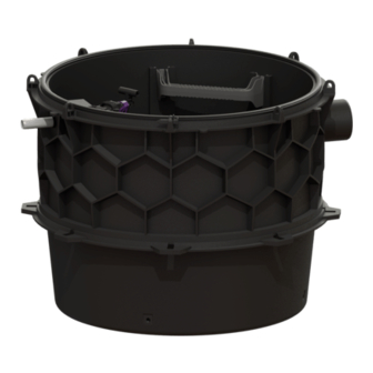
Produktbeschreibung Baugruppen und Funktionsmerkmale Abb. [7] Abwasserpumpe Rückflussverhinderer Druckleitungsanschluss DN32 PE-Haltekonsole für Aufnahme der Sonde und Druckleitung Anbohrfläche für Entlüftungsleitung DN100 Steighilfen Anbohrfläche für Kabelleerrohr Zulauf Niveaugeber (Tauchglocke) Technikmodul Schachtmodul Alarmsensor (optische Sonde) 9 / 148 2019/12 010-993... -
Page 10: Sicherheit
Sicherheit Sicherheit Bestimmungsgemäße Verwendung Die Pumpstation ist ausschließlich für das Abpumpen von fäkalienfreiem Abwasser zu verwenden. Ein Einsatz in explosionsgefährdeter Umgebung ist ausschließlich dann zulässig, wenn die Pumpstation in der dafür vorgesehenen Konfiguration (ATEX-zertifiziert) ist. Alle nicht durch eine ausdrückliche und schriftliche Freigabe des Herstellers erfolgten •... -
Page 11: Gefahren, Die Vom Produkt Ausgehen
Sicherheit Gefahren, die vom Produkt ausgehen Gefahr durch gesundheitsgefährdende Atmosphäre Bei Arbeiten in der Anlage besteht die Gefahr, dass die Atmosphäre im Schachtsystem gesundheitsgefährdend ist. Auf ausreichende Belüftung achten und ggf. Sicherheitseinrichtungen wie z.B. Multigaswarngerät verwenden. Gefahr durch Lärm Der Betrieb der Pumpstation kann einen hohen Lärmpegel verursachen. Tragen Sie bei Bedarf entsprechende Schutzausrüstung und sorgen Sie für schalldämmende Maßnahmen. -
Page 12: Montage
Montage Montage Aqualift Comfort Aqualift Comfort Abb. [8] Allgemeines zur Montage – Zur elektrischen Absicherung der Pumpstation ist ein FI-Schutzschalter vorzusehen. – Das Schaltgerät der Pumpstation sollte so positioniert sein, dass es zu keiner unbefugten Benutzung kommen kann. Wird die Pumpstation unbeabsichtigt ausgeschaltet, können Folgeschäden im Gebäude auftreten. -
Page 13: Steigleitung Montieren
Montage Steigleitung montieren Pumpe montieren Abb. [10] Abb. [9] • Steigleitung <1> mit zwei Schrauben <3> an • Pumpe <2> in den Schacht einbringen. die Pumpe <2> montieren. Dazu diese langsam bis zum Schachtboden hinunterlassen. • Steigleitung der Pumpe <1> mit dem Einhandverschluss <3> am Rückflussverhinderer <4> anschließen. 13 / 148 2019/12 010-993... -
Page 14: Tauchglocke Montieren
Montage Tauchglocke montieren • Tauchglocke wie abgebildet montieren • L = 180 mm Abb. [11] Schaltgerät montieren (nur bei Varianten mit Schaltgerät) • Schaltgerät gemäß der dem Schaltgerät beiliegenden Anleitung montieren • Alle Kabel der elektrischen Komponenten sicher verlegen Elektrische Anschlüsse und Anschluss Niveausensor herstellen Sicherstellen, dass das Schaltgerät während der Montagearbeiten von der Spannungsversorgung getrennt ist. -
Page 15: Erstinbetriebnahme
Montage Erstinbetriebnahme Ein Trockenlauf der Abwasserpumpe(n) über einen längeren Zeitraum (>30 Sekunden) ist unbedingt zu vermeiden, sie könnte(n) beschädigt werden. Niemals Abwasserpumpen einschalten, wenn der Anlagenbehälter nicht mindestens bis zum Pegelstand Minimum befüllt ist. 4.7.1 Schaltgerät initialisieren (nur bei Varianten mit Schaltgerät) •... -
Page 16: Funktionskontrolle
Montage 4.7.2 Funktionskontrolle Sicherheitshinweise im Kapitel 3 beachten. • Pumpstation ausschalten (ggfs. Netzstecker ziehen) • Ggf. Deckel des Anlagenbehälters (Schacht) öffnen • Anlagenbehälter soweit mit Wasser füllen, dass das Schaltniveau der Anlage überschritten ist (mindestens jedoch soweit, dass Pumpen vollständig mit Wasser bedeckt sind). •... -
Page 17: Betrieb
Betrieb Betrieb Alle Rückflussverhinderer müssen während des Betriebs funktionstüchtig sein, siehe <2> auf Abb. [7], Seite 9 Bei Varianten ohne Schaltgerät ist die Anlage betriebsbereit, sobald der Netzanschluss hergestellt wurde. Einschalten • Netzanschluss herstellen, nach erfolgreichem Systemtest erscheint im Display <23> das Menü 0 Systeminfo und die grüne LED <22>... -
Page 18: Ausschalten
Betrieb Ausschalten • Netzanschluss trennen, der akustische Alarm ertönt und die Alarm-LED blinkt. • Akustischen Alarm ausschalten, dazu Taste <69> (Abb. [14]) betätigen (ca. 1 Sekunde), bis im Display das Alarmsymbol durchgestrichen dargestellt wird. • Schaltgerät ausschalten, dazu Taste <69> so lange gedrückt halten (mindestens 5 Sekunden), bis das Display und die Alarm-LED ausgeschaltet werden. -
Page 19: Wartung
Wartung Wartung Sicherheitshinweise für die Wartung Gefahr durch giftige und gesundheitsgefährdende Dämpfe, Gase und Stoffe (z. B. Bakterien, Viren). Befindet sich die Pumpstation in einem Schacht, sind darin notwendige Arbeiten ausschließlich durch Fachpersonal (siehe 3.2) durchzuführen. Vor einem Öffnen von Gehäuseabdeckungen, Steckern und Kabeln (auch an den potentialfreien Kontakten), sind diese spannungsfrei zu machen. -
Page 20: Wartungsvorbereitung
Wartung Wartungsvorbereitung – Sicherstellen, dass der Zulauf zur Pumpstation während der Wartung unbenutzt bleibt. – Sicherstellen, dass die Pumpstation während der Wartungsarbeiten nicht unbeabsichtigt eingeschaltet werden kann. Das gilt im Besonderen, wenn sich das Schaltgerät in einem anderen Raum als der Anlagenbehälter befindet. - Page 21 Wartung • Tauchglocke <9> säubern, dass sie frei von Anhaftungen und Ablagerungen ist Anlagenbehälter reinigen • Anlagenbehälter (Schacht) entleeren. Das kann mit einem Nasssauger durchgeführt werden • Sicherstellen, dass der Anlagenbehälter (Schacht) frei von Schweb- und Feststoffen ist, ggf. reinigen Abb. [13] Rückflussverhinderer reinigen ACHTUNG: Wird der Einhandverschluss geöffnet, läuft das Wasser, welches sich im Druckrohr befindet, ungehindert heraus.
-
Page 22: Fehlersuche
Fehlersuche Fehlersuche Alle Arbeiten, die über die im Kapitel Betrieb beschriebenen Tätigkeiten hinausgehen, dürfen nur von Fachpersonal (siehe 3.2) durchgeführt werden. • Hinweise wie unter 6.1 beschrieben beachten und ggf. durchführen Fehler Mögliche Ursache Abhilfemaßnahme / Kapitel Batteriefehler Batterie fehlt, ist defekt oder Spannung Batterieanschluss prüfen, ggf. -
Page 23: Technische Daten
Technische Daten Technische Daten Pumpen Pumpe 1200 Gewicht [kg] Leistung P1 0,65 Leistung P2 Drehzahl [u/min] 2800 Betriebsspannung [V] 230V / 50Hz Nennstrom [A] Förderleistung max [m³/h] 15,5 Förderhöhe max. [m] Förderguttemperatur max. [°C] Schutzart IP68 (3m WS) Schutzklasse Motorschutz extern Steckertyp codierter Stecker/Schukostecker... -
Page 24: Anschlüsse
230 V Duo Version Comfort Gewicht [kg] Betriebsspannung [V] 230V / 50Hz Schutzart IP54 Schutzklasse Steckertyp Schuko Anschlusskabel 1,4m 3 x 1,5mm² erforderliche Absicherung C 16A & RCD Abmessungen, Volumen Siehe auch Einbauanleitung KESSEL Technikschacht LW1000 (010-701). 24 / 148 010-993 2019/12... - Page 25 INSTRUCTIONS FOR INSTALLATION, OPERATION AND MAINTENANCE KESSEL Aqualift S XL pumping station wet installation (with one-handed closures) Product advantages For faecal-free wastewater Large useful volume Simple and fast installation Low weight High safety level due to resistance to aggressive media...
- Page 26 Table of Contents Introduction Product description, general ..........................28 General information on these operating and maintenance instructions ..........29 How it works ................................30 Product description Nameplate ..................................31 Scope of delivery (pallet allocation) ........................32 Scope of delivery (small parts package)......................33 Assemblies and functional characteristics .......................34 Safety Intended use ................................35 Personnel selection and qualification ........................35...
- Page 27 Maintenance tasks ..............................44 6.4.1 Replace battery ................................44 6.4.2 Clean the pumping station ............................44 Troubleshooting Technical data Pumps ....................................47 Characteristic curves ..............................47 Connections ................................48 Useful volumes / switching level .........................48 Control unit ..................................48 Dimensions, volume ..............................48 Declaration of perfomance ..............................145 27 / 148 2019/12 010-993...
-
Page 28: Introduction
Introduction Dear customer, As a premium manufacturer of innovative products for draining technology, KESSEL offers integrated system solutions and customer-oriented service. We hereby aspire to the highest quality standards and focus firmly on sustainability - not just when it comes to manufacturing our products, but also with respect to their long-term operation, so that you and your property are protected long term. -
Page 29: General Information On These Operating And Maintenance Instructions
Introduction General information on these operating and maintenance instructions Symbols and keys used <1> Reference in the text to a key number in an illustration Reference to an illustration (Figure) • Work step Work step in numbered order – List Italics Italic type: Reference to a section / item in the control menu CAUTION: Warns of a hazard for persons and material. -
Page 30: How It Works
Introduction How it works Aqualift Comfort Ill. [2] 30 / 148 010-993 2019/12... -
Page 31: Product Description
Product description Product description Type plate Pumpstation Aqualift S XL Pumpstation Aqualift S XL xxxxx xxxxx xxxV xxHz x,xA x,xkW xxm³/h S3 xx% ED IP xx (xmWS/xh) Ser. Nr. xxxxxxxxx www.kessel.de/info RevStd.: x.x MM/JJ DIN-EN 1 xxxxxxxxxx Ill. [3] Information on the type plate <11>... -
Page 32: Scope Of Delivery (Pallet Allocation)
Product description Scope of delivery (pallet allocation) Ill. [5] Technical module incl. small parts box and pumps 32 / 148 010-993 2019/12... -
Page 33: Scope Of Delivery (Small Parts Package)
Product description Scope of delivery (small parts package) Ill. [6] Riser(s) Level sensor (submersible bell) Control unit Documents (installation instructions, Declaration of Conformity, ...) Pump(s) 33 / 148 2019/12 010-993... -
Page 34: Assemblies And Functional Characteristics
Product description Assemblies and functional characteristics Ill. [7] Wastewater pump Backwater preventer Pressure pipe connection DN32 PE bracket for holding the probe and pressure pipe Tapping area for ventilation pipe DN100 Access steps Tapping area for reserve conduit Inlet Level sensor (submersible bell) Technical module Chamber module Alarm sensor (optical probe) -
Page 35: Safety
Safety Safety Intended use The system is to be used only for pumping faecal-free wastewater. Use of the system in a potentially explosive environment (ATEX) is only permitted when the pumping station is certified accordingly (ATEX certified). • modifications or attachments •... -
Page 36: Hazards Caused By The Product
Safety Hazards caused by the product Hazard due to harmful atmosphere There is a risk of a hazardous atmosphere occurring in the inspection chamber during work. Make sure the system is well aerated and use safety equipment such as e.g. a multi-gas warning device if appropriate. Noise hazard Operation of the pumping station can cause a high noise level. -
Page 37: Installation
Installation Installation Aqualift Comfort Aqualift Comfort Ill. [8] General installation information – A residual current circuit breaker must be provided as electrical protection for the pumping station. – The pumping station‘s control unit should be positioned to prevent any unauthorised use. Consequential damage can occur in the building if the pumping station is switched off accidentally. -
Page 38: Install The Riser
Installation Install the riser Install the pump Ill. [9] Ill. [10] • Use two screws <3>> to mount the riser • Place the pump <2> in the chamber. To do <1> on the pump <2> this, lower it slowly onto the bottom of the chamber. -
Page 39: Install The Control Unit (Only For Variants With Control Unit)
Installation Install the control unit (only for variants with control unit) • Install the control unit as described in the instructions enclosed with it. • Safely lay all cables of the electrical components. Make electrical connections and level sensor connection Make sure that the control unit is disconnected from the power supply during installation work. -
Page 40: Functional Check
Installation Date / Time • Set the respective flashing figure in date and time and confirm with OK. Following the last entry, the menu item Product type is displayed. Product type • Select Aqualift Mono or Duo pumping station and confirm with OK, the menu item System variant displayed. -
Page 41: Operation
Operation Operation The backwater preventers must be functional during operation, see <2> in Fig. [7], page 34 For variants without control unit the installation is ready for operation as soon as the connection to the mains power supply has been made. Switching on * Connect to the mains voltage, following a successful system test menu 0 System info appears in the display <23>... -
Page 42: Switch Off
Operation Switch off • Disconnect the mains supply, the acoustic alarm sounds and the alarm LED flashes. • Switch off the acoustic alarm; to do this press button <69> (Fig. [14]) (approx. 1 second) until the alarm symbol on the display is crossed out. •... -
Page 43: Maintenance
Maintenance Maintenance Maintenance safety instructions Hazard due to toxic and harmful fumes, gases and substances (e. g. bacteria, viruses). If the pumping station is located in a chamber, any necessary work must always be carried out by skilled personnel only (see 3.2). Before opening housing covers, plugs and cables (including those on floating switches) they must be safely isolated from the power supply (de-energised). -
Page 44: Maintenance Preparation
Maintenance Maintenance preparation – Make sure that the inlet to the pumping station is not used during maintenance work. – Make sure that the pumping station cannot be switched on accidentally during maintenance work. This applies in particular if the control unit is in a different room than the system tank. Maintenance tasks 6.4.1 Replace battery... - Page 45 Maintenance Cleaning the system tank • Drain the system tank (inspection chamber) This can be done using a wet vacuum cleaner • Make sure that the system tank (inspection chamber) is free from suspended matter and solids, clean if necessary Cleaning the backwater preventer Ill.
-
Page 46: Troubleshooting
Troubleshooting Troubleshooting All work exceeding the activities described in the Operation chapter may only be carried out by skilled personnel (see 3.2). • Follow the instructions described in 6.1 and carry out if necessary Error Possible cause Remedial measure / Chapter Battery fault Battery is missing, is defective or voltage Check battery connection, if necessary... -
Page 47: Technical Data
Technical data Technical data Pumps Pump 1200 Weight [kg] Power P1 Power P2 0,36 Speed [rpm] 2800 Operating voltage [V] 230V / 50Hz Nominal current [A] Max. delivery rate [m³/h] 15.5 Max. delivery head [m] Max. temperature of pumped material [°C] Degree of protection IP68 (3m WC/48 h) Protection class... -
Page 48: Connections
230V / 50Hz Degree of protection IP54 Protection class Plug type Safety plug Connection cable 1.4m, 3 x 1.5mm² Required fusing C 16A & RCD Dimensions, volume See also installation instructions for KESSEL technical chamber LW1000 (010-701) 48 / 148 010-993 2019/12... - Page 49 INSTRUCTIONS DE POSE, D‘UTILISATION ET DE MAINTENANCE KESSEL Poste de pompage Aqualift S XL pose immergée (avec fermetures manuelles) Avantages du produit Pour eaux usées sans matières fécales Grand volume utile Montage simple et rapide Faible poids Sécurité élevée grâce à...
- Page 50 Sommaire Introduction Description générale du produit .........................52 Informations d‘ordre général concernant les présentes instructions d‘utilisation et de maintenance ..............................52 Principe de fonctionnement ..........................53 Description du produit Plaque signalétique ..............................54 Détail de livraison (répartition sur palettes) ....................55 Détail de livraison (colis contenant les petits accessoires) .................56 Sous-groupes et éléments fonctionnels ......................57 Sécurité...
- Page 51 Préparation de la maintenance ..........................68 Interventions de maintenance ..........................68 6.4.1 Remplacement de la batterie ..........................68 6.4.2 Nettoyage du poste de pompage ........................68 Aide au diagnostic Caractéristiques techniques Pompes ..................................71 Courbes caractéristiques ............................71 Raccords ..................................72 Volumes utiles / niveau de commutation ......................72 Gestionnaire ................................72 Dimensions, volume ..............................72 Déclaration de conformité...
-
Page 52: Introduction
En qualité de producteur de pointe de produits novateurs dans le domaine de la technique d’assainissement, KESSEL propose des réponses systématiques globales et un service orienté aux besoins de la clientèle. Nous misons simultanément sur les normes de qualité les plus élevées et une durabilité conséquente – non seulement lors de la fabrication de nos produits, mais également pour leur utilisation à... -
Page 53: Informations D'ordre Général Concernant Les Présentes Instructions D'utilisation Et De Maintenance
Introduction Informations d‘ordre général concernant les présentes instructions d‘utilisation et de maintenance Pictogrammes et légendes utilisés <1> Information dans le texte attirant l‘attention sur un numéro de légende dans une figure Renvoi à une figure • Étape opératoire Étape opératoire par ordre d‘apparition numéroté –... -
Page 54: Description Du Produit
Description du produit Description du produit Plaque signalétique Pumpstation Aqualift S XL Pumpstation Aqualift S XL xxxxx xxxxx xxxV xxHz x,xA x,xkW xxm³/h S3 xx% ED IP xx (xmWS/xh) Ser. Nr. xxxxxxxxx www.kessel.de/info RevStd.: x.x MM/JJ DIN-EN 1 xxxxxxxxxx Ill. [3] Informations figurant sur la plaque signalétique <11>... -
Page 55: Détail De Livraison (Répartition Sur Palettes)
Description du produit Détail de livraison (répartition sur palettes) Ill. [5] Module technique y compris le colis contenant les petits accessoires et les pompes 55 / 148 2019/12 010-993... -
Page 56: Détail De Livraison (Colis Contenant Les Petits Accessoires)
Description du produit Détail de livraison (colis contenant les petits accessoires) Ill. [6] Conduite/s ascendante/s Capteur de niveau (cloche submersible) Gestionnaire Documents (instructions de pose et d‘utilisation, déclaration de conformité...) Pompe/s 56 / 148 010-993 2019/12... -
Page 57: Sous-Groupes Et Éléments Fonctionnels
Description du produit Sous-groupes et éléments fonctionnels Ill. [7] Pompe d‘assainissement Anti-retour Raccordement de la conduite de refoulement DN32 Console en PE de logement du capteur et de la conduite de refoulement Surface de perçage pour la conduite de purge d‘air DN100 Échelle d‘accès Surfaces de perçage pour le conduit de câbles Entrée... -
Page 58: Sécurité
Sécurité Sécurité Utilisation conforme à l‘usage prévu Le poste de pompage sert exclusivement au refoulement des eaux usées sans matières fécales. L‘utilisation dans des zones à risque d‘explosion est exclusivement permise si le poste de pompage dispose de la configuration nécessaire dans ce contexte (certification ATEX). Il faut savoir, à... -
Page 59: Risques Liés Au Produit
Sécurité Risques liés au produit Risque lié à une atmosphère nuisible à la santé L‘atmosphère dans le regard peut nuire à la santé lors de travaux à effectuer dans le système de regard. Veiller toujours à une ventilation suffisante et utiliser des équipements et dispositifs de sécurité tels qu‘un appareil multigaz. -
Page 60: Montage
Montage Montage Aqualift Comfort Aqualift Comfort Ill. [8] Conseils de montage d‘ordre général – Il convient de prévoir un interrupteur de protection contre les courants de surcharge électrique du poste de pompage. – Positionner le gestionnaire du poste de pompage de sorte à exclure toute utilisation non autorisée. La mise hors circuit par inadvertance du poste de pompage risque de causer des dommages consécutifs ou indirects au bâtiment. -
Page 61: Montage De La Conduite Ascendante
Montage Montage de la conduite Montage de la pompe ascendante Ill. [10] Ill. [9] • Monter la conduite ascendante <1> avec • Placer la pompe <2> dans le regard. Pour deux vis <3> à la pompe <2> ce faire, la descendre avec précaution jusqu’au fond du regard. •... -
Page 62: Montage De La Cloche Submersible
Montage Montage de la cloche submersible • Monter la cloche submersible selon la figure ci-contre • L = 200 mm Ill. [11] Montage du gestionnaire (uniquement pour modèles avec gestionnaire) • Monter le gestionnaire suivant les instructions jointes au gestionnaire • Veiller à une pose sans risque de tous les câbles des composants électriques Réalisation des connexions électriques et raccordement du détecteur de niveau S‘assurer que le gestionnaire a été... -
Page 63: Première Mise En Service
Montage Première mise en service Exclure impérativement tout fonctionnement à sec de la/des pompe/s d‘assainissement d‘une durée supérieure à 30 secondes qui risquerait de la/les détériorer. Ne jamais mettre les pompes d‘assainissement en marche tant que le bac collecteur n‘est pas rempli jusqu‘au niveau minimum. 4.7.1 Initialisation du gestionnaire (uniquement pour modèles avec gestionnaire) •... -
Page 64: Contrôle Fonctionnel
Montage 4.7.2 Contrôle fonctionnel Observer les consignes de sécurité du cahpitre 3. • Déconnecter le poste de pompage ( retirer la fiche de secteur si nécessaire) • Au besoin, ouvrir le couvercle du bac collecteur (regard) • Remplir le bac collecteur de sorte que le niveau d’eau soit plus élevé que le niveau de commutation du système (cependant au moins jusqu’à... -
Page 65: Service
Service Service Tous les anti retours doivent demeurer aptes au fonctionnement pendant le service, voir <2> de la Fig. [7], page Les modèles sans gestionnaire sont en ordre de marche dès le raccordement au secteur du système. Mise en circuit •... -
Page 66: Mise Hors Circuit
Service Mise hors circuit • Couper le raccordement au réseau, l‘alarme acoustique retentit et la diode d‘alarme clignote. • Débrancher l‘alarme acoustique, pour ce faire appuyer sur la touche <69> (Fig. [14]) (pendant env. 1 seconde) jusqu‘à ce que le pictogramme de l‘alarme affiché à l‘écran soit barré. •... -
Page 67: Maintenance
Maintenance Maintenance Consignes de sécurité spécifiques à la maintenance Risque lié aux vapeurs, gaz et substances toxiques ou nuisible à la santé (p. ex. les bactéries, virus). Les travaux à effectuer sur un poste de pompage logé dans un regard demeurent réservés au domaine de compétence exclusif de personnes qualifiées (voir 3.2). -
Page 68: Préparation De La Maintenance
Maintenance Préparation de la maintenance – S‘assurer que l‘entrée du poste de pompage ne sera pas utilisée pendant la maintenance. – S‘assurer qu‘on ne puisse pas mettre le poste de pompage en circuit par inadvertance pendant les interventions de maintenance. Cette disposition possède une importance particulière si le gestionnaire se situe dans une autre pièce que le bac collecteur. - Page 69 Maintenance Nettoyage de la cloche submersible • Nettoyer la cloche submersible <9> de sorte à ce qu’elle soit exempte d’incrustations et de dépôts Nettoyage du bac collecteur • Vider le bac collecteur (regard). Se servir par exemple d‘un aspirateur à eau •...
-
Page 70: Aide Au Diagnostic
Aide au diagnostic Aide au diagnostic Toutes les interventions et activités non décrites dans le chapitre du service demeurent réservées au domaine de compétence de personnes qualifiées (voir 3.2). • Tenir compte des observations décrites suivant 6.1 et exécuter si besoin est Défaut Cause possible Remède / chapitre... -
Page 71: Caractéristiques Techniques
Caractéristiques techniques Caractéristiques techniques Pompes Pompe 1200 Poids (kg) Puissance P1 Puissance P2 0,36 Régime [tr/min] 2800 Tension de service [V] 230V / 50Hz Courant nominal [A] Débit maxi de la pompe [m³/h] 15,5 Hauteur de relevage maxi [m] Température du fluide refoulé maxi [°C] Type de protection IP68 (3 m colonne d’eau / 48 h) -
Page 72: Raccords
Type de connecteur Schuko (fiche à contact de protection) Câble de raccordement 1,4 m, 3 x 1,5 mm² Protection par fusible C 16A & RCD nécessaire Dimensions, volume Voir également les instructions de pose du regard technique KESSEL LW1000 (010-701) 72 / 148 010-993 2019/12... - Page 73 ISTRUZIONI PER L‘INSTALLAZIONE, IL FUNZIONAMENTO E LA MANUTENZIONE KESSEL Stazione di pompaggio Aqualift S XL installazione in umido (con chiusure mono - manuali) Vantaggi del prodotto Per le acque di scarico non contenenti sostanze fecali Grande volume utile Installazione semplice e...
- Page 74 Indice Introduzione Descrizione del prodotto, in generale........................76 Indicazioni generali sulle presenti istruzioni per l’uso e la manutenzione ...........77 Principio di funzionamento ...........................77 Descrizione del prodotto Targhetta..................................78 Dotazione (suddivisione delle palette) ......................79 Dotazione (pacchetto della minuteria) ......................80 Gruppi costruttivi e caratteristiche funzionali ....................81 Sicurezza Uso conforme alla destinazione ...........................82 Scelta e qualifica del personale ..........................82...
- Page 75 Mansioni di manutenzione ............................92 6.4.1 Sostituzione della batteria .............................92 6.4.2 Pulizia della stazione di pompaggio ........................92 Ricerca di errori Dati tecnici Pompe ...................................95 Curve caratteristiche ..............................95 Collegamenti ................................96 Volumi utili/livello di commutazione .........................96 Quadro elettrico .................................96 Misure, volumi ................................96 Dichiarazione di conformità 75 / 148 2019/12 010-993...
-
Page 76: Introduzione
Introduzione Cara cliente, caro cliente, in qualità di produttore premium di prodotti innovativi per la tecnica di drenaggio, KESSEL offre soluzioni di sistema integrate e un servizio orientato al cliente. Puntiamo sui massimi standard qualitativi e ci impegniamo coerentemente per la sostenibilità – non ci impegniamo solo nella produzione dei nostri prodotti, ma anche rispetto al funzionamento a lungo termine, in modo che la vostra proprietà... -
Page 77: Indicazioni Generali Sulle Presenti Istruzioni Per L'uso E La Manutenzione
Introduzione Indicazioni generali sulle presenti istruzioni per l’uso e la manutenzione Simboli utilizzati e legenda <1> Riferimento nel testo a un numero di legenda in un’immagine Riferimento a una figura • Passo di lavoro Passo di lavoro in una sequenza numerata –... -
Page 78: Descrizione Del Prodotto
Descrizione del prodotto Descrizione del prodotto Targhetta Pumpstation Aqualift S XL Pumpstation Aqualift S XL xxxxx xxxxx xxxV xxHz x,xA x,xkW xxm³/h S3 xx% ED IP xx (xmWS/xh) Ser. Nr. xxxxxxxxx www.kessel.de/info RevStd.: x.x MM/JJ DIN-EN 1 xxxxxxxxxx Fig. [3] Informazioni sulla targhetta <11>... -
Page 79: Dotazione (Suddivisione Delle Palette)
Descrizione del prodotto Dotazione (suddivisione delle palette) Fig. [5] Modulo tecnico comprensivo di scatola della minuteria e pompe 79 / 148 2019/12 010-993... -
Page 80: Dotazione (Pacchetto Della Minuteria)
Descrizione del prodotto Dotazione (pacchetto della minuteria) Fig. [6] Colonna/e montante/i Sensore di livello (campana ad immersione) Quadro elettrico Documenti (EBA, dichiarazione di conformità, ecc.) Pompa/e 80 / 148 010-993 2019/12... -
Page 81: Gruppi Costruttivi E Caratteristiche Funzionali
Descrizione del prodotto Gruppi costruttivi e caratteristiche funzionali Fig. [7] Pompa delle acque di scarico Blocco antiriflusso Collegamento del condotto di mandata DN32 Console di supporto per l’alloggiamento della sonda e del condotto di mandata Superficie perforabile per il condotto di sfiato DN100 Gradini di salita Superficie perforabile per il tubo vuoto per cavi Entrata... -
Page 82: Sicurezza
Sicurezza Sicurezza Uso conforme alla destinazione La stazione di pompaggio è destinata esclusivamente al pompaggio di svuotamento delle acque di scarico non contenenti sostanze fecali. Un impiego negli ambienti a rischio di esplosione è ammesso esclusivamente se la stazione di pompaggio presenta l’apposita configurazione (certificazione ATEX). -
Page 83: Pericoli Derivanti Dal Prodotto
Sicurezza Pericoli derivanti dal prodotto Percoli causati dalle atmosfere nocive In caso di lavori nel pozzetto sussiste il pericolo che l’atmosfera all’interno del sistema di pozzetto sia nociva. Garantire una ventilazione sufficiente e impiegare eventualmente dei dispositivi di sicurezza, come ad esempio un rilevatore di gas universale. -
Page 84: Montaggio
Montaggio Montaggio Aqualift Comfort Aqualift Comfort Fig. [8] Informazioni generali sul montaggio – Per la sicurezza elettrica della stazione di pompaggio deve essere previsto un interruttore differenziale. – Il quadro elettrico della stazione di pompaggio dovrebbe essere posizionato in modo che non possa avvenire alcun uso non autorizzato. -
Page 85: Montaggio Della Colonna Montante
Montaggio Montaggio della colonna Montaggio della pompa montante Fig. [10] Fig. [9] • Montare la colonna montante <1> alla • Collocare la pompa <2> nel pozzetto pompa <2> con due viti <3> calandola lentamente fino al fondo del pozzetto. • Collegare la colonna montante <1> al blocco antiriflusso <4>... -
Page 86: Montaggio Della Campana Ad Immersione
Montaggio Montaggio della campana ad immersione • Montare la campana ad immersione come illustrato • L = 180 mm Fig. [11] Montaggio del quadro elettrico (solo per le varianti con quadro elettrico) • Montare il quadro elettrico ai sensi delle istruzioni allegate al quadro elettrico stesso •... -
Page 87: Prima Messa In Funzione
Montaggio Prima messa in funzione Un funzionamento a secco della/e pompa/e delle acque di scarico per un periodo prolungato (>30 secondi) deve essere assolutamente evitato, in quanto potrebbe causare danni. Non accendere mai le pompe per le acque di scarico se il contenitore dell’impianto non è pieno almeno fino al livello dell’acqua minimo. 4.7.1 Inizializzazione del quadro elettrico (solo per le varianti con quadro elettrico) •... -
Page 88: Controllo Di Funzionamento
Montaggio 4.7.2 Controllo di funzionamento Rispettare le avvertenze di sicurezza nel capitolo 3. • Spegnere la stazione di pompaggio (eventualmente estrarre la spina di rete elettrica) • Eventualmente aprire il coperchio del contenitore dell’impianto (pozzetto) • Riempire il contenitore dell’impianto con acqua fino al superamento del livello di commutazione dell’impianto (in ogni caso almeno fino a coprire completamente d’acqua la pompa). -
Page 89: Funzionamento
Funzionamento Funzionamento Tutti i blocchi antiriflusso devono essere funzionanti durante il funzionamento; vedere <2> nella figura [7], pagina 81 Per le varianti senza quadro elettrico, l’impianto è pronto al funzionamento non appena viene realizzato il collegamento alla rete elettrica. Accensione •... -
Page 90: Spegnimento
Funzionamento Spegnimento • Scollegare il collegamento alla rete elettrica, l’allarme acustico suona e il LED d’allarme lampeggia. • Spegnere l’allarme acustico, a tale fine azionare il tasto <69> (figura [14]) (circa 1 secondo) fino a che il simbolo di allarme sul display appare barrato. •... -
Page 91: Manutenzione
Manutenzione Manutenzione Avvertenze di sicurezza per la manutenzione Pericolo a causa di vapori, gas o sostanze velenose o nocive (ad esempio batteri o virus). Qualora la stazione di pompaggio si trovi in un pozzetto, i lavori necessari all’interno di quest’ultimo dovranno essere eseguiti esclusivamente da personale specializzato (vedere 3.2). -
Page 92: Preparazione Della Manutenzione
Manutenzione Preparazione della manutenzione – Accertare che l’entrata alla stazione di pompaggio rimanga inutilizzata durante la manutenzione. – Accertare che la stazione di pompaggio non possa essere attivata inavvertitamente durante i lavori di manutenzione. Questo vale in particolare se il quadro elettrico si trova in un locale diverso rispetto al contenitore dell’impianto. - Page 93 Manutenzione Pulizia della campana ad immersione • Pulire la campana ad immersione <9> in modo da liberarla da incrostazioni e depositi Pulizia del contenitore dell’impianto • Svuotare il contenitore dell’impianto (pozzetto). Questa operazione può avvenire con un aspiraliquidi • Accertare che il contenitore dell’impianto (pozzetto) sia privo di sostanze in sospensione e solide, eventualmente lavarlo Fig.
-
Page 94: Ricerca Di Errori
Ricerca di errori Ricerca di errori Tutti i lavori ulteriori rispetto alle mansioni descritte nel capitolo Funzionamento possono essere eseguiti solo da personale specializzato (vedere 3.2). • Osservare ed eventualmente eseguire le indicazioni descritte al punto 6.1 Errore Possibile causa Rimedio / Capitolo Errore della batteria La batteria manca, è... -
Page 95: Dati Tecnici
Dati tecnici Dati tecnici Pompe Pompa 1200 Peso [kg] Potenza P1 Potenza P2 0,36 Numero di giri [giri/minuto] 2800 Tensione di funzionamento [V] 230 V / 50 Hz Corrente nominale [A] Portata max [m³/h] 15,5 Prevalenza max [m] Temperatura materiale trasportato max [°C] Tipo di protezione IP68 (3 mH2O/48 ore) -
Page 96: Collegamenti
Classe di protezione Tipo di connettore Schuko Cavo di collegamento 1,4 m 3 x 1,5 mm² Protezione necessaria C 16 A & RCD Misure, volumi Vedere anche le istruzioni di installazione del pozzetto tecnico KESSEL LW1000 (010- 96 / 148 010-993 2019/12... - Page 97 HANDLEIDING VOOR DE INBOUW, HET GEBRUIK EN HET ONDERHOUD KESSEL Pompstation Aqualift S XL Natte opstelling (met eenhands sluiting) Productvoordelen Voor afvalwater zonder fecaliën Groot nuttig volume Eenvoudige en snelle montage Laag gewicht Grote betrouwbaarheid door bestendigheid tegen agressieve media Grondwaterbestendig tot 3 m...
- Page 98 Inhoudsopgave Introductie Productomschrijving, algemeen ..........................100 Algemene instructies bij deze gebruiks- en onderhoudshandleiding ..........101 Functieprincipe ................................101 Productomschrijving Typeplaatje ..................................102 Leveringsomvang (verdeeld over pallets) ......................103 Leveringsomvang (pakket kleine onderdelen) ....................104 Modules en functiekenmerken ..........................105 Veiligheid Reglementair gebruik ..............................106 Personeelskeuze en -kwalificatie .........................106 Organisatorische veiligheidsmaatregelen .......................106 Gevaren die uitgaan van het product ........................107 Montage...
- Page 99 Onderhoudsactiviteiten ............................116 6.4.1 Batterij vervangen ..............................116 6.4.2 Het pompstation reinigen ............................116 Opsporen van storingen Technische gegevens Pompen ..................................119 Karakteristieken .................................119 Aansluitingen ................................120 Nuttige volumes/schakelniveau ..........................120 Besturingskast ................................120 Afmetingen, volume ..............................120 Verklaring van overeenstemming 99 / 148 2019/12 010-993...
-
Page 100: Introductie
Introductie Beste klant, Als premium fabrikant van innovatieve producten voor de afwateringstechniek biedt KESSEL op de totaliteit gerichte systeemoplossingen en op de klant georiënteerde service. Wij stellen hierbij maximale kwaliteitsnormen en zetten consequent in op duurzaamheid - niet alleen bij de productie van onze producten, maar ook met het oog op hun langdurige gebruik. -
Page 101: Algemene Instructies Bij Deze Gebruiks- En Onderhoudshandleiding
Introductie Algemene instructies bij deze gebruiks- en onderhoudshandleiding Gebruikte symbolen en legenda <1> Verwijzing in de tekst naar een legendanummer op een afbeelding Referentie naar een afbeelding • Uit te voeren stap Uit te voeren stap in genummerde volgorde – Opsomming Cursief Cursieve letterweergave: Referentie naar een paragraaf/punt in het besturingsmenu... -
Page 102: Productomschrijving
Productomschrijving Productomschrijving Typeplaatje Pumpstation Aqualift S XL Pumpstation Aqualift S XL xxxxx xxxxx xxxV xxHz x,xA x,xkW xxm³/h S3 xx% ED IP xx (xmWS/xh) Ser. Nr. xxxxxxxxx www.kessel.de/info RevStd.: x.x MM/JJ DIN-EN 1 xxxxxxxxxx Afb. [3] Informatie op het typeplaatje <11>... -
Page 103: Leveringsomvang (Verdeeld Over Pallets)
Productomschrijving Leveringsomvang (verdeeld over pallets) Afb. [5] Techniekmodule incl. doos met kleine onderdelen en pompen 103 / 148 2019/12 010-993... -
Page 104: Leveringsomvang (Pakket Kleine Onderdelen)
Productomschrijving Leveringsomvang (pakket kleine onderdelen) Afb. [6] Stijbuis/stijgbuizen Niveaugever (dompelpomp) Besturingskast Documenten (EBA, verklaring van overeenstemming...) Pomp(en) 104 / 148 010-993 2019/12... -
Page 105: Modules En Functiekenmerken
Productomschrijving Modules en functiekenmerken Afb. [7] Vuilwaterpomp Terugslagklep Aansluiting persbuis DN32 PE-console voor de bevestiging van de sonde en de persbuis Boorvlak voor ontluchtingsleiding DN100 Klimhulpmiddelen Boorvlak voor lege kabelbuis Aanvoer Niveaugever (dompelpomp) Techniekmodule Schachtmodule Alarmsensor (optische sonde) 105 / 148 2019/12 010-993... -
Page 106: Veiligheid
Veiligheid Veiligheid Reglementair gebruik Het pompstation mag uitsluitend worden gebruikt voor het wegpompen van fecaliënvrij afvalwater. Het pompstation mag uitsluitend in een explosiegevaarlijke omgeving worden gebruikt wanneer het pompstation voor dat doel is geconfigureerd (ATEX-gecertificeerd). Alle niet door een expliciete en schriftelijke vrijgave van de fabrikant uitgevoerde •... -
Page 107: Gevaren Die Uitgaan Van Het Product
Veiligheid Gevaren die uitgaan van het product Gevaar door voor de gezondheid gevaarlijke atmosfeer Bij werkzaamheden in de schacht bestaat het gevaar dat de atmosfeer in het schachtsysteem gevaarlijk is voor de gezondheid. Op voldoende ventilatie letten en eventueel veiligheidsvoorzieningen zoals bijv. gebruik maken van multigas-waarschuwingsapparaat. -
Page 108: Montage
Montage Montage Aqualift Comfort Aqualift Comfort Afb. [8] Algemene zaken m.b.t. de montage – Voor de elektrische beveiliging van het pompstation moet een aardlekschakelaar aanwezig en aangesloten zijn. – De besturingskast van het pompstation moet zodanig gepositioneerd zijn, dat gebruik door onbevoegden onmogelijk is. -
Page 109: De Stijgbuis Monteren
Montage Afb. [9] Afb. [10] • De stijgbuis <1> met twee bouten <3> op • De pomp <2> in de schacht laten zakken. de pomp <2> monteren Deze daarvoor langzaam tot aan de bodem van de schacht laten zakken. • De stijgbuis van de pomp <1> met de eenhands sluiting <3>... -
Page 110: De Dompelpomp Monteren
Montage De dompelpomp monteren • De dompelpomp monteren zoals afgebeeld • L = 180 mm Afb. [11] Besturingskast monteren (alleen bij varianten met besturingskast) • De besturingskast overeenkomstig de bij de besturingskast bijgevoegde handleiding monteren. • Alle kabels van de elektrische componenten op een veilige manier aanbrengen. Elektrische aansluitingen en de aansluiting van de niveausensor tot stand brengen Waarborgen dat de besturingskast tijdens de montagewerkzaamheden losgekoppeld is van de voedingsspanning. -
Page 111: Eerste Inbedrijfstelling
Montage Eerste inbedrijfstelling Er moet absoluut worden voorkomen dat de afvalwaterpomp(en) gedurende langere tijd (> 30 seconden) drooglopen; zij kunnen dan beschadigd raken. Nooit afvalwaterpompen inschakelen, als de systeemtank niet ten minste tot het minimale peil is gevuld. 4.7.1 Besturingskast initialiseren (alleen bij varianten met besturingskast) •... -
Page 112: Functiecontrole
Montage 4.7.2 Functiecontrole De veiligheidsinstructies in hoofdstuk 3 in acht nemen. • Het pompstation uitschakelen (eventueel de stekker uit het het stopcontact trekken) • Eventueel het deksel van de systeemtank (schacht) openen • De systeemtank zover met water vullen tot het schakelniveau van installatie wordt overschreden (minimaal echter zover dat de pompen volledig onder water staan). -
Page 113: Gebruik
Gebruik Gebruik De terugstroombeveiliging moet tijdens de werking correct functioneren, zie <2> op afb. [7], pagina 105 Bij varianten zonder besturingskast is de installatie bedrijfsklaar zodra de aansluiting op het stroomnet tot stand is gebracht. Inschakelen • De stroomaansluiting tot stand brengen, na een succesvolle systeemtest verschijnt op het display <23>... -
Page 114: De Pompen Met De Hand Besturen
Gebruik • Het akoestisch alarm uitschakelen, daartoe toets <69> (afb. [14]), gebruiken (ca. 1 seconde), totdat op het display het alarmsymbool doorgestreept wordt weergegeven. • De besturingskast uitschakelen, daartoe toets <69> net zolang ingedrukt houden (minstens 5 seconden), totdat het display en de alarm-LED uitgeschakeld worden. De besturingskast is uitgeschakeld. -
Page 115: Onderhoud
Onderhoud Onderhoud Veiligheidsinstructies voor het onderhoud Gevaar door giftige en voor de gezondheid gevaarlijke dampen, gassen en stoffen (bijv. bacteriën, virussen). Als het pompstation zich in een schacht bevindt, moeten vereiste werkzaamheden daarin uitsluitend door geschoold personeel (zie 3.2) worden uitgevoerd. Voordat afdekkingen van behuizingen, stekkers en kabels worden geopend (ook bij de potentiaalvrije contacten), moeten deze worden losgekoppeld van de voedingsspanning. -
Page 116: Onderhoudsvoorbereiding
Onderhoud Onderhoudsvoorbereiding – Waarborgen dat de aanvoer naar het pompstation gedurende het onderhoud niet wordt gebruikt. – Waarborgen dat het pompstation gedurende de onderhoudswerkzaamheden niet per ongeluk kan worden ingeschakeld. Dit geldt in het bijzonder, wanneer het besturingskast in een andere ruimte dan de systeemtank is opgesteld. - Page 117 Onderhoud De dompelpomp reinigen • De dompelpomp <9> schoonmaken waarbij de pomp moet worden ontdaan van aangehecht materiaal en sediment De systeemtank reinigen • De systeemtank (schacht) leegmaken. Dat kan met een natzuiger worden gedaan • Waarborgen dat de systeemtank (schacht) geen zwevende en vaste stoffen bevat, eventueel reinigen.
-
Page 118: Opsporen Van Storingen
Opsporen van storingen Opsporen van storingen Alle werkzaamheden die afwijken van de in het hoofdstuk Werking beschreven handelingen, mogen alleen door geschoold personeel (zie 3.2) worden uitgevoerd. • De aanwijzingen zoals beschreven onder punt 6.1 in acht nemen en zo nodig doorvoeren. Storing Mogelijke oorzaak Verhelpen/hoofdstuk... -
Page 119: Technische Gegevens
Technische gegevens Technische gegevens Pompen Pomp 1200 Gewicht [kg] Capaciteit P1 Capaciteit P2 0,36 Toerental [omw/min] 2.800 Bedrijfsspanning [V] 230 V/50 Hz Nominale stroomsterkte [A] Pompcapaciteit max. [m³/h] 15,5 Opvoerhoogte max. [m] Temperatuur transportmateriaal max. [°C] Beschermingsklasse IP68 (3m Ws/48 h) Beveiligingsklasse Motorbeveiliging extern... -
Page 120: Aansluitingen
Comfort Gewicht [kg] Bedrijfsspanning [V] 230 V/50 Hz Beschermingsklasse IP54 Beveiligingsklasse Stekkertype geaard Netkabel 1,4 m, 3 x 1,5 mm² Vereiste zekering C 16A & RCD Afmetingen, volume Zie ook de inbouwhandleiding KESSEL-techniekschacht LW1000 (010 120 / 148 010-993 2019/12... - Page 121 INSTRUKCJA MONTAŻU, OBSŁUGI I KONSERWACJI KESSEL Stacja pomp Aqualift S XL ustawienie mokre (z jednoręcznymi szybkimi zamknięciami) Zalety produktu Do ścieków nie zawierających fekalia Duża pojemność użytkowa Szybki i łatwy montaż Mały ciężar Wysokie bezpieczeństwo dzięki odporności na agresywne czynniki...
- Page 122 Spis treści Wstęp Ogólny opis produktu ..............................124 Informacje ogólne dotyczące niniejszej instrukcji obsługi i konserwacji ..........125 Zasada działania .................................125 Opis produktu Tabliczka znamionowa ............................126 Zakres dostawy (rozłożenie na paletach) ......................127 Zakres dostawy (paczka z małymi częściami) ....................128 Podzespoły i funkcje ..............................129 Bezpieczeństwo Zastosowanie zgodnie z przeznaczeniem ......................130 Wybór i kwalifikacje personelu ..........................130...
- Page 123 Prace konserwacyjne..............................140 6.4.1 Wymiana baterii .................................140 6.4.2 Czyszczenie stacji pomp ............................140 Wyszukiwanie błędów Dane techniczne Pompy ....................................143 Charakterystyki ................................143 Objętości użytkowe / poziom przełączania .....................144 Urządzenie sterujące ..............................144 Wymiary, pojemność ..............................144 Deklaracja zgodności 123 / 148 2019/12 010-993...
-
Page 124: Wstęp
Wstęp Szanowna Klientko, szanowny Kliencie! Jako producent najwyższej klasy innowacyjnych produktów z zakresu techniki odwadniania firma KESSEL oferuje kompleksowe rozwiązania systemowe i serwis odpowiadający potrzebom klientów. Stawiamy przy tym na najwyższe standardy jakości i konsekwentnie dążymy do zrównoważonego rozwoju, nie tylko w produkcji naszych produktów, ale również... -
Page 125: Informacje Ogólne Dotyczące Niniejszej Instrukcji Obsługi I Konserwacji
Wstęp Informacje ogólne dotyczące niniejszej instrukcji obsługi i konserwacji Stosowane symbole i legendy <1> Wskazówka w treści odnosząca się do numeru legendy na rysunku Odniesienie do rysunku • Krok roboczy Krok roboczy w ponumerowanej kolejności – Wyliczenie Kursywa Tekst pisany kursywą: Odniesienie do fragmentu/punktu w menu sterowania OSTROŻNIE: Ostrzeżenie przed zagrożeniem dla osób lub rzeczy. -
Page 126: Opis Produktu
Opis produktu Opis produktu Tabliczka znamionowa Pumpstation Aqualift S XL Pumpstation Aqualift S XL xxxxx xxxxx xxxV xxHz x,xA x,xkW xxm³/h S3 xx% ED IP xx (xmWS/xh) Ser. Nr. xxxxxxxxx www.kessel.de/info RevStd.: x.x MM/JJ DIN-EN 1 xxxxxxxxxx Rys. [3] Informacje na tabliczce znamionowej <11>... -
Page 127: Zakres Dostawy (Rozłożenie Na Paletach)
Opis produktu Zakres dostawy (rozłożenie na paletach) Rys. [5] Moduł techniczny z kartonem z małymi częściami i pompami 127 / 148 2019/12 010-993... -
Page 128: Zakres Dostawy (Paczka Z Małymi Częściami)
Opis produktu Zakres dostawy (paczka z małymi częściami) Rys. [6] Pion(-y) instalacyjny(-e) Czujnik poziomu (dzwon zanurzeniowy) Urządzenie sterujące Dokumenty (EBA, deklaracja zgodności...) Pompa(-y) 128 / 148 010-993 2019/12... -
Page 129: Podzespoły I Funkcje
Opis produktu Podzespoły i funkcje Rys. [7] Pompa ściekowa Zawór zwrotny Przyłącze przewodu tłocznego DN32 Konsola mocująca z polietylenu na sondę i przewód tłoczny Miejsce na otwór na przewód odpowietrzający DN100 Stopnie złazowe Miejsce na otwór na rurę ochronną na kable Dopływ Czujnik poziomu (dzwon zanurzeniowy) Moduł... -
Page 130: Bezpieczeństwo
Bezpieczeństwo Bezpieczeństwo Zastosowanie zgodnie z przeznaczeniem Stacja pomp jest przeznaczona wyłącznie do pompowania ścieków nie zawierających fekalia. Użycie w otoczeniu zagrożonym wybuchem jest dopuszczalne tylko wtedy, gdy stacja pomp znajduje się w odpowiedniej konfiguracji (certyfikat ATEX). Wszelkie bez wyraźnej i pisemnej zgody producenta •... -
Page 131: Zagrożenia Ze Strony Produktu
Bezpieczeństwo Zagrożenia ze strony produktu Zagrożenie wskutek szkodliwej dla zdrowia atmosfery Podczas prac w studzience istnieje ryzyko, że atmosfera w systemie studzienki jest szkodliwa dla zdrowia. Zwrócić uwagę na wystarczającą wentylację i ew. użyć urządzeń bezpieczeństwa, np. przenośnego wykrywacza gazu. Zagrożenie hałasem Podczas pracy stacji pomp może powstawać... -
Page 132: Montaż
Montaż Montaż Aqualift Comfort Aqualift Comfort Rys. [8] Informacje ogólne na temat montażu – Stacja pomp wyposażona jest w zabezpieczający elektrycznie bezpiecznik różnicowo-prądowy. – Urządzenie sterujące stacji pomp należy ustawić w takim miejscu, aby nie mogło dojść do jego nieupoważnionego użycia. W przypadku niezamierzonego wyłączenia stacji pomp, może dojść do szkód następczych w budynku. - Page 133 Montaż Rys. [9] Rys. [10] • Zamontować pion instalacyjny <1> za • Umieścić pompę <2> w studzience. pomocą dwóch śrub <3> na pompie <2>. Spuścić ją w tym celu powoli aż na dno studzienki. • Podłączyć pion instalacyjny pompy <1> z szybkim zamknięciem <3> do zaworu zwrotnego <4>.
-
Page 134: Montaż Dzwonu Zanurzeniowego
Montaż Montaż dzwonu zanurzeniowego • Zamontować dzwon zanurzeniowy w sposób przedstawiony na rysunku. • L = 180 mm Rys. [11] Montaż urządzenia sterującego (tylko w wariantach z urządzeniem sterującym) • Zamontować urządzenie sterujące zgodnie z instrukcją załączoną do urządzenia sterującego. •... -
Page 135: Pierwsze Uruchomienie
Montaż Pierwsze uruchomienie Bezwzględnie unikać pracy pompy ściekowej / pomp ściekowych na sucho przez dłuższy czas (>30 sekund), gdyż może to prowadzić do jej/ich uszkodzenia. Nigdy nie włączać pomp ściekowych, jeżeli zbiornik urządzenia nie jest napełniony przynajmniej do poziomu minimum. 4.7.1 Inicjalizacja urządzenia sterującego (tylko w wariantach z urządzeniem sterującym) •... -
Page 136: Kontrola Działania
Montaż 4.7.2 Kontrola działania Przestrzegać wskazówek bezpieczeństwa w rozdziale 3. • Wyłączyć stację pomp (ew. wyciągnąć wtyczkę z gniazda). • W razie potrzeby otworzyć pokrywę zbiornika urządzenia (studzienki). • Napełnić zbiornik urządzenia wodą powyżej poziomu przełączania urządzenia (przynajmniej na tyle, aby pompy były całkowicie zakryte wodą). •... -
Page 137: Eksploatacja
Eksploatacja Eksploatacja Wszystkie zawory zwrotne muszą być podczas pracy sprawne, patrz <2> na rys. [7], strona 129 W wariantach bez urządzenia sterującego urządzenie jest gotowe do pracy po podłączeniu do sieci. Włączenie • Podłączyć urządzenie do sieci, po pomyślnym teście systemu na wyświetlaczu <23>... -
Page 138: Wyłączenie
Eksploatacja Wyłączenie • Odłączyć przyłącze sieciowe, rozbrzmiewa alarm akustyczny i miga dioda LED alarmu. • Aby wyłączyć alarm akustyczny, nacisnąć przycisk <69> (rys. [14]) (przez ok. 1 sekundę), aż na wyświetlaczu pojawi się przekreślony symbol alarmu. • Wyłączyć urządzenie sterujące przez naciśnięcie przycisku <69> (i przytrzymanie go przez przynajmniej 5 sekund), aż... -
Page 139: Konserwacja
Konserwacja Konserwacja Wskazówki bezpieczeństwa dotyczące konserwacji Zagrożenie wskutek trujących i zagrażających zdrowiu oparów, gazów i substancji (np. bakterie, wirusy). Jeżeli stacja pomp znajduje się w studzience, niezbędne prace może wykonywać wyłącznie personel specjalistyczny (patrz 3.2). Przed otwarciem osłon obudowy, wtyczek i kabli (również kontaktów bezpotencjałowych) należy je odłączyć od napięcia. -
Page 140: Przygotowanie Do Konserwacji
Konserwacja Przygotowanie do konserwacji – Zapewnić, aby dopływ do stacji pomp nie był używany na czas konserwacji. – Zapewnić, aby niemożliwe było przypadkowe włączenie stacji pomp podczas prac konserwacyjnych. Dotyczy to zwłaszcza przypadku, gdy urządzenie sterujące znajduje się w innym pomieszczeniu niż zbiornik urządzenia. - Page 141 Konserwacja Czyszczenie dzwonu zanurzeniowego • Wyczyścić dzwon zanurzeniowy <9>, aż będzie wolny od osadów. Czyszczenie zbiornika urządzenia • Opróżnić zbiornik urządzenia (studzienkę). Można to zrobić za pomocą odkurzacza przemysłowego na mokro. • Upewnić się, że zbiornik urządzenia (studzienka) jest wolny od zawiesin i ciał...
-
Page 142: Wyszukiwanie Błędów
Wyszukiwanie błędów Wyszukiwanie błędów Wszelkie prace, wykraczające poza zakres czynności opisanych w rozdziale „Eksploatacja”, może wykonywać wyłącznie personel specjalistyczny (patrz 3.2). • Przestrzegać wskazówek w punkcie 6.1 i ewentualnie postępować według instrukcji. Błąd Możliwa przyczyna Rozwiązanie / rozdział Błąd baterii Brak baterii, uszkodzona bateria lub za Sprawdzić... -
Page 143: Dane Techniczne
Dane techniczne Dane techniczne Pompy Pompa 1200 Ciężar [kg] Moc P1 Moc P2 0,36 Prędkość obrotowa [obr./min] 2800 Napięcie robocze [V] 230V / 50Hz Prąd znamionowy [A] Wydajność maks. [m³/h] 15,5 Wysokość tłoczenia maks. [m] Temperatura nosiwa maks. [°C] Stopień ochrony IP68 (3m Ws/48 h) Klasa ochrony Ochrona silnika... -
Page 144: Objętości Użytkowe / Poziom Przełączania
Stopień ochrony IP54 Klasa ochrony Rodzaj wtyczki z zestykiem ochronnym Kabel instalacyjny 1,4 m 3 x 1,5 mm² Wymagane zabezpieczenie C 16A & RCD Wymiary, pojemność Patrz również instalacja zabudowy studzienki technicznej firmy KESSEL LW1000 (010-701) 144 / 148 010-993 2019/12... -
Page 145: Konformitätserklärung
Deklaracja zgodności / DOP Deklaracja zgodności / DOP 145 / 148 2019/12 010-993... - Page 146 Deklaracja zgodności / DOP 146 / 148 010-993 2019/12...
- Page 147 Notizen Notizen 147 / 148 2019/12 010-993...
- Page 148 Notizen 148 / 148 010-993 2019/12...
Need help?
Do you have a question about the Aqualift S XL and is the answer not in the manual?
Questions and answers